


334T 338XPT
336 339XP
English

CONTENTS
Introduction .................................................... |
3 |
Safety instructions ......................................... |
4 |
Symbol explanation ....................................... |
5 |
Technical Data ................................................ |
6 |
Tools ................................................................ |
8 |
Trouble shooting .......................................... |
10 |
Service data 334T/338XPT ........................... |
12 |
Service data 336/339XP ............................... |
14 |
Safety equipment ......................................... |
16 |
Starter............................................................ |
23 |
Ignition system ............................................. |
25 |
Centrifugal clutch ......................................... |
27 |
Carburettor ................................................... |
29 |
Tank unit ....................................................... |
41 |
AV-System ..................................................... |
46 |
Crankshaft, Piston and Cylinder................. |
47 |
Bar bolt.......................................................... |
51 |
Oil pump........................................................ |
52 |
2 – English

INTRODUCTION
General
This Workshop Manual provides a comprehensive description of how to trouble shoot, repair and test the chain saw. A description of different safety measures that should be taken during repair work is also given.
Layout
This Workshop Manual can be used in two different ways:
•For the repair of a particular system on the chain saw.
•For dismantling and assembly of the entire chain saw.
Safety
NOTE!
The section dealing with safety must be read and understood by all those carrying out repair work or service on the chain saw.
Warning symbols can be found in this Workshop Manual and on the chain saw. See the chapter "Symbol explanation". A new decal must be applied as soon as possible if a warning symbol on the chain saw has been damaged or is missing so that the greatest possible safety can be obtained when using the chain saw.
Target group
When producing this Workshop Manual the assumption has been made that personnel who use it have general knowledge in the repair and service of small engines.
The Workshop Manual must be read and understood by personnel who will carry out repair work and service on the chain saw. The Manual is also suitable for use when training new employees.
Modifications
Modifications will be successively introduced on the chain saw during production. When these modifications affect the service and/or spare parts, separate service information will be sent out on each occasion. This means that in time this Workshop manual will become out of date. In order to prevent this, the Manual should be read together with all service information concerning the chain saw in question.
Tools
Special tools must be used during specific steps. All service tools are listed in the Workshop Manual. Usage is evident from respective sections.
Always use Husqvarna’s original:
•Spare parts
•Service tools
•Accessories
Repair of a particular system
When a particular system on the chain saw is to be repaired, proceed as follows:
1.Look up the page for the system in question.
2.Carry out the sections:
•Dismantling
•Cleaning and Inspection
•Assembly
Dismantling and assembly of the entire chain saw
Proceed as follows when the entire chain saw is to be dismantled and assembled:
1.Look up the chapter "Starter" which deals with the Starter and carry out the instructions set out under Dismantling.
2.Work forward in the Manual and carry out Dismantling in the order set out in the sections.
3.Go back to the chapter "Starter" and carry out the instructions under Cleaning and Inspection.
4.Work forward in the Manual and carry out Cleaning and Inspection in the order set out in the sections.
5.Order or take out all requisite spare parts from the stores.
6.Look up the chapter "Oil pump" which deals with the Oil pump and carry out the instructions set out under Assembly.
7.Work back towards the beginning of the Manual and carry out Assembly in the order set out in the sections.
Some sections include a Description of the actual unit in order to increase the basic understanding.
Numbering
Position references to components inside the figures are designated A, B, etc.
The position references restart in each new section.
English – 3
SAFETY REGULATIONS
General instructions
The workshop where chain saw repairs are to be done must be equipped with safety equipment as set out in local provisions.
No one may repair the chain saw unless they have read and understood the content of this Workshop Manual.
This Workshop Manual contains the following boxes in relevant places. Warning boxes are positioned before the procedures they refer to.
WARNING!
The warning box warns of the risk of personal injury if the instructions are not followed.
NOTE!
This box warns of material damage if the instructions are not followed.
Special instructions
The fuel used in the chain saw has the following hazardous properties:
•The fluid and its vapour are poisonous.
•Can cause skin irritation.
•Is highly inflammable.
The bar, chain and clutch cover (chain brake) must be fitted before the saw is started otherwise the clutch can work loose and cause personal injury.
Wear ear-muffs when test running.
Do not use the saw until it has been adjusted so that the chain remains still when idling.
After test running, do not touch the muffler until it has cooled. Risk for burns.
Insufficient chain lubrication can result in chain breakage, which can cause serious, even life-threatening injury.
Ensure that the spring in the starter does not fly out and cause personal injury.
If the spring tension is activated on the starter pulley when it is to be taken up, the spring can fly out and cause personal injury.
Check that the brake is applied when removing the pressure spring on the chain brake. Otherwise the pressure spring can fly out and cause personal injury.
Do not direct the compressed air jet towards the body when using compressed air. Air can penetrate in to the blood circulation, which means mortal danger.
4 – English
SYMBOL EXPLANATION
Symbols
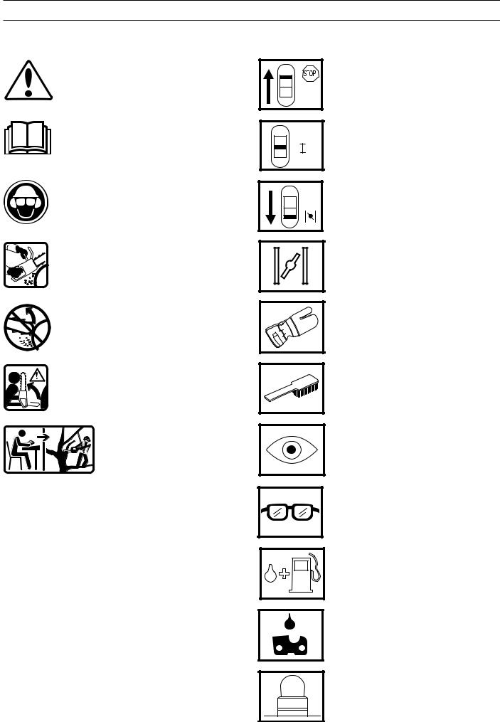
WARNING! Chain saws can be dangerous! Careless or incorrect usage can result in serious injury even death to operator or others.
Read through the Operator Guide carefully and understand the content before using the chain saw.
Always use:
•An approved safety helmet
•Approved ear-muffs
• Protective glasses or a visor
Always use both hands whenever possible with all chain saw work.
Avoid contact between the tip of the bar and objects.
Contact with the tip of the bar can result in the bar being suddenly thrown upwards and backwards, which can result in serious injury.
This saw is only intended for persons especially trained in tree conservation. See the Operator Guide!
Inspection and/or maintenance should be carried out with the engine switched off, and with the stop switch in the "STOP" position.
Operating mode
Choke, 334T, 338XPT
Choke, 336, 339XP
Always wear approved protective gloves.
Regular cleaning is required.
Visual inspection.
Protective glasses or visor must be worn.
Fuel refilling.
Oil refilling and adjustment of the oil flow.
Air purge
English – 5
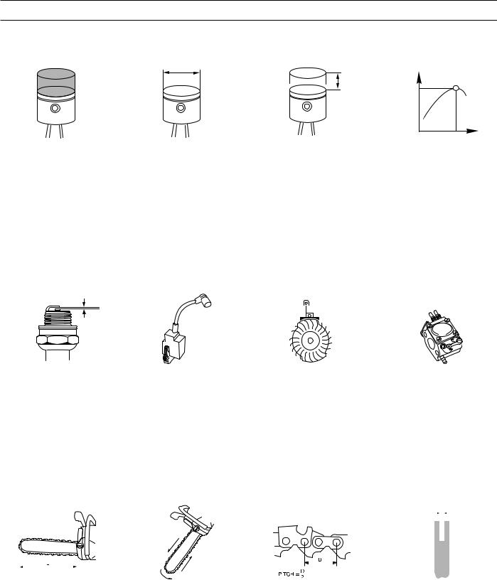
TECHNICAL DATA
Stroke volume |
Cylinder diameter |
Stroke length |
Max. output/speed |
|||||
cm3/cubic inch |
Ø mm/Ø inch |
mm/inch |
kW/hp/r/min |
|||||
336: |
35,2/2,1 |
38/1,5 |
31/1,22 |
1,5/2,0/9 600 |
||||
334T: |
35,2/2,1 |
38/1,5 |
31/1,22 |
1,5/2,0/9 600 |
||||
338XPT: |
39,0/2,4 |
40/1,6 |
31/1,22 |
1,7/2,3/9 600 |
||||
339XP: |
39,0/2,4 |
40/1,6 |
31/1,22 |
1,7/2,3/9 600 |
||||
|
|
|
|
|
|
|
|
|
|
|
|
|
|
|
|
|
|
|
|
|
|
|
|
|
|
|
|
Electrode gap |
Ignition system |
|
Air gap |
|
Carburettor type |
||||||||||||||
|
|
mm/inch |
|
|
mm/inch |
|
|
|
|
|
|
|
|
|||||||
336: |
|
0,7/0,028 |
|
SEM/CD |
0,3/0,01 |
|
|
ZAMA C1Q |
||||||||||||
334T: |
0,7/0,028 |
|
SEM/CD |
0,3/0,01 |
|
|
ZAMA C1Q |
|||||||||||||
338XPT: 0,7/0,028 |
SEM/CD |
0,3/0,01 |
|
|
ZAMA C1Q |
|||||||||||||||
339XP: |
0,7/0,028 |
|
SEM/CD |
0,3/0,01 |
|
|
ZAMA C1Q |
|||||||||||||
|
|
|
|
|
|
|
|
|
|
|
|
|
|
|
|
|
|
|
|
|
|
|
|
|
|
|
|
|
|
|
|
|
|
|
|
|
|
|
|
|
|
|
|
|
|
|
|
|
|
|
|
|
|
|
|
|
|
|
|
|
|
|
|
|
|
|
|
|
|
|
|
|
|
|
|
|
|
|
|
|
|
|
|
|
|
|
|
|
|
|
|
|
|
|
|
|
|
|
|
|
|
|
|
|
|
|
|
|
|
|
|
|
|
|
|
|
|
|
|
|
|
|
|
|
|
|
|
|
|
|
|
|
|
|
|
|
|
|
|
|
|
|
|
|
|
|
|
|
|
|
|
|
|
|
|
|
|
|
|
|
|
|
|
|
|
|
|
|
|
|
|
|
|
|
|
|
|
|
|
|
|
|
|
|
|
|
|
|
|
Bar length |
Chain speed at |
Chain pitch |
Drive link |
|
|
max output |
|
|
|
cm/inch |
m/s |
inch |
mm/inch |
336: |
33-46/13-18 |
18,3 |
3/8/0,0325 |
1,3/0,050 |
334T: 29-36/12-14 |
18,3 |
3/8 |
1,3/0,050 |
|
338XPT: 29-41/12-16 |
18,3 |
3/8 |
1,3/0,050 |
|
339XP: 33-46/13-18 |
18,3 |
0,0325 |
1,3/0,050 |
|
6 – English
TECHNICAL DATA
|
|
|
|
|
|
|
|
|
|
|
|
|
|
|
|
|
|
|
|
|
|
|
|
|
|
|
|
|
|
|
|
|
|
|
|
|
|
|
|
|
|
|
|
|
|
|
|
|
|
|
|
|
|
|
|
|
|
|
|
|
|
|
|
|
|
|
|
|
|
|
|
|
|
|
|
|
|
|
|
|
|
|
|
|
|
|
|
|
|
|
|
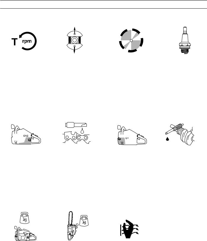
Idling speed |
Engage speed |
|
Max. speed |
Spark plug |
||||||||||||||||||
|
r/min |
|
|
|
|
|
|
r/min |
|
r/min |
|
|
|
|||||||||
336: |
2 800 |
4 100 |
|
13 800 |
Champion RCJ7Y |
|||||||||||||||||
|
|
|
|
|
|
|
|
|
|
|
|
|
|
|
|
|
|
|
|
NGK BPMR 7A |
||
334T: |
2 800 |
4 100 |
|
13 800 |
Champion RCJ7Y |
|||||||||||||||||
|
|
|
|
|
|
|
|
|
|
|
|
|
|
|
|
|
|
|
|
NGK BPMR 7A |
||
338XPT: |
2 800 |
4 100 |
|
13 800 |
Champion RCJ7Y |
|||||||||||||||||
|
|
|
|
|
|
|
|
|
|
|
|
|
|
|
|
|
|
|
|
NGK BPMR 7A |
||
339XP: |
2 800 |
4 100 |
|
13 800 |
Champion RCJ7Y |
|||||||||||||||||
|
|
|
|
|
|
|
|
|
|
|
|
|
|
|
|
|
|
|
|
NGK BPMR 7A |
||
|
|
|
|
|
|
|
|
|
|
|
|
|
|
|
|
|
|
|
|
|
|
|
|
|
|
|
|
|
|
|
|
|
|
|
|
|
|
|
|
|
|
|
|
|
|
|
|
|
|
|
|
|
|
|
|
|
|
|
|
|
|
|
|
|
|
|
|
|
|
|
|
|
|
|
|
|
|
|
|
|
|
|
|
|
|
|
|
|
|
|
|
|
|
|
|
|
|
|
|
|
|
|
|
|
|
|
|
|
|
|
|
|
|
|
Volume fuel tank |
Capacity oil pump |
Volume oil tank |
Automatic oil pump |
|
Litre/US pint |
cm3/min |
Litre/US pint |
|
|
336: |
0,36/0,76 |
3-7 |
0,20/0,42 |
Yes |
334T: |
0,3/0,63 |
3-7 |
0,16/0,34 |
Yes |
338XPT: |
0,3/0,63 |
3-7 |
0,16/0,34 |
Yes |
339XP: |
0,36/0,76 |
3-7 |
0,20/0,42 |
Yes |
Weight without chain and bar |
Weight with chain and bar |
Handle heater |
|
|
kg/lbs |
kg/lbs |
Watt/ r/min |
336: |
3,8/8,4 |
4,5/9,8 |
- / - |
334T: |
3,4/7,5 |
4,0/8,8 |
- / - |
338XPT: |
3,4/7,5 |
4,0/8,8 |
- / - |
339XP: |
3,8/8,4 |
3,8/8,4 |
- / - |
English – 7
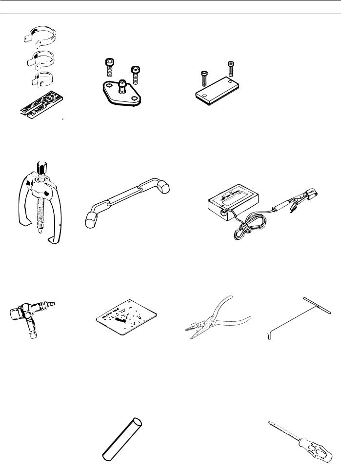
TOOLS
1 |
2 |
3 |
4 |
5 |
6 |
7 |
8 |
9 |
10 |
11 |
12 |
13 |
14 |
15 |
8 – English

TOOLS
The tools listed here are service tools intended for use on the chain saw in question. In addition to these tools, a standard set of hand tools is required.
Pos |
Description |
Used for |
Order No. |
|
|
|
|
1 |
Piston assembly set |
Assembling the piston |
502 50 70-01 |
2 |
Cover plate, inlet |
Sealing the inlet manifold |
502 52 01-01 |
3 |
Cover plate exhaust |
Sealing the exhaust port |
502 52 31-01 |
4 |
Pressure tester |
Produce pressure when leakage testing |
502 50 38-01 |
5 |
Puller |
Removing bearings from the crankshaft |
504 90 90-01 |
6 |
Piston stop |
Locking the crankshaft |
502 54 15-01 |
7 |
Tachometer |
Adjusting the carburettor |
502 71 14-01 |
8 |
Test spark plug |
Checking the ignition module |
502 71 13-01 |
9 |
Feeler gauges, air gap |
Adjustment of the ignition module |
502 51 34-02 |
10 |
Assembly bar |
Assembly of the spark plug guard |
502 50 06-01 |
11 |
Hook for fuel filter |
Lifting out the fuel filter |
502 50 83-01 |
12 |
Assembly fixture |
Assembling the chain saw |
502 51 02-01 |
13 |
Punch |
Dismantling the flywheel |
502 51 94-01 |
14 |
Allen key, 3 mm |
For M4 bolts |
502 50 19-01 |
14 |
Allen key, 4 mm |
For M5 bolts |
502 50 18-01 |
15 |
Hexagonal screwdriver, 3 mm |
For M4 bolts |
502 50 86-01 |
15 |
Hexagonal screwdriver, 4 mm |
For M5 bolts |
502 50 87-01 |
|
|
|
|
English – 9

TROUBLE SHOOTING
Trouble shooting chart
The different faults that can occur on the chain saw are divided into four groups as follows. Within each group possible operating faults are listed to the left while the probable fault alternatives are listed to the right. The most likely fault is listed first, etc.
Starting
Difficult to start |
Adjust the L-screw |
|
Air filter blocked |
|
Choke does not work |
|
Worn choke axle |
|
Worn choke valve |
|
Blocked fuel filter |
|
Blocked fuel line |
|
Piston ring seized |
|
Blocked impulse channel |
|
|
Carburettor leaks |
Loose or faulty fuel pipe |
fuel |
Hole in diaphragm |
|
Worn needle/needle tip |
|
Control system sticking |
|
Control system set too high |
|
Leaking control system (air or fuel) |
|
Cover on the carburettor’s pump side |
|
is loose |
|
|
Floods when the |
Worn needle/needle tip |
engine is not running |
Control system set too high |
|
|
|
Control system sticking |
|
|
Idling (low speed)
Does not idle |
Adjust the L-screw |
|
Leaking inlet manifold (rubber) |
|
Loose carburettor mounting |
|
Loose or faulty fuel pipe |
|
Blocked fuel filter |
|
Blocked fuel line |
|
Tank ventilator blocked |
|
Throttle valve axle stiff |
|
Throttle sticks |
|
Defective throttle return spring |
|
Bent valve axle stop |
|
Faulty diffuser jet |
|
|
Too rich idling |
Adjust the L screw |
|
Worn needle/needle tip |
|
Control system set too high |
|
Worn lever arm in the control system |
|
Leaking diaphragm/cover plate |
|
Control system sticking |
|
|
Idling (low speed) (continued)
Idling with closed L |
Worn needle/needle tip |
screw |
Leaking diaphragm/cover plate |
|
|
|
Control system sticking |
|
Worn lever arm in the control system |
|
Faulty diffuser jet |
|
|
Uneven idling |
Blocked fuel filter |
|
Blocked fuel line |
|
Leaking inlet manifold (rubber) |
|
Loose carburettor mounting |
|
Worn throttle valve axle |
|
Loose throttle valve screw |
|
Worn throttle valve |
|
Control system sticking |
|
Leaking control system (air or fuel) |
|
Control system’s centre knob is worn |
|
Hole in diaphragm |
|
Leaking diaphragm/cover plate |
|
Leaking crankcase |
|
|
L-screw needs |
Blocked fuel line |
constant adjustment |
Control system set too high |
|
|
|
Control system sticking |
|
Leaking control system (air or fuel) |
|
Leaking diaphragm/cover plate |
|
Faulty diffuser jet |
|
Leaking crankcase |
|
|
Too much fuel while |
Control system set too high |
idling |
Control system sticking |
|
|
|
Damaged control system |
|
Worn needle/needle tip |
|
Leaking diaphragm/cover plate |
|
Incorrectly fitted control system |
|
|
10 – English
TROUBLE SHOOTING
High speed
Will not run at full |
Adjust H-screw |
throttle |
Blocked air filter |
|
|
|
Tank ventilator blocked |
|
Blocked fuel filter |
|
Blocked fuel line |
|
Loose or faulty fuel pipe |
|
Impulse channel leaking |
|
Blocked impulse channel |
|
Cover on the carburettor’s pump side |
|
is loose |
|
Faulty pump diaphragm |
|
Leaking inlet manifold (rubber) |
|
Loose carburettor mounting |
|
Control system set too low |
|
Damaged control system |
|
Incorrectly fitted control system |
|
Leaking diaphragm/cover plate |
|
Control system sticking |
|
Blocked muffler |
|
|
Low power |
Adjust H-screw |
|
Tank ventilator blocked |
|
Blocked fuel filter |
|
Impulse channel leaking |
|
Blocked impulse channel |
|
Cover on the carburettor’s pump side |
|
is loose |
|
Faulty pump diaphragm |
|
Blocked air filter |
|
Control system sticking |
|
Leaking control system (air or fuel) |
|
Control system incorrectly assembled |
|
Loose diaphragm |
|
Hole in diaphragm |
|
Leaking diaphragm/cover plate |
|
|
Will not "four stroke" |
Tank ventilator blocked |
|
Blocked fuel filter |
|
Blocked fuel line |
|
Loose or faulty fuel pipe |
|
Impulse channel leaking |
|
Blocked impulse channel |
|
Cover on the carburettor’s pump side |
|
is loose |
|
Faulty pump diaphragm |
|
Leaking inlet manifold (rubber) |
|
Loose carburettor mounting |
|
Control system set too low |
|
Leaking control system (air or fuel) |
|
Control system incorrectly assembled |
|
Loose diaphragm |
|
Hole in diaphragm |
|
Leaking diaphragm/cover plate |
|
|
Acceleration and retardation
Does not accelerate |
Adjust the L-screw |
|
Adjust H-screw |
|
Blocked air filter |
|
Tank ventilator blocked |
|
Blocked fuel filter |
|
Blocked fuel line |
|
Loose or faulty fuel pipe |
|
Blocked impulse channel |
|
Cover on the carburettor’s pump side |
|
is loose |
|
Faulty pump diaphragm |
|
Leaking inlet manifold (rubber) |
|
Loose carburettor mounting |
|
Control system set too low |
|
Incorrectly fitted control system |
|
Control system sticking |
|
Faulty diffuser jet |
|
Blocked muffler |
|
|
Engine stalls when |
Adjust the L-screw |
throttle is released |
Adjust H-screw |
|
Faulty pump diaphragm |
|
Control system set too high |
|
Control system sticking |
|
Faulty diffuser jet |
|
|
Too rich acceleration |
Adjust the L screw |
|
Adjust H-screw |
|
Blocked air filter |
|
Faulty pump diaphragm |
|
Faulty diffuser jet |
|
|
Trouble shooting methods
In addition to faults given in the above schematic, trouble shooting can be carried out on a specific component or specific chain saw system. The different procedures are described in respective sections and are as follows:
1.Pressure testing the carburettor. See the chapter "Carburettor".
2.Pressure testing the crankcase and cylinder. See the chapter "Crankshaft, Piston and Cylinder".
English – 11
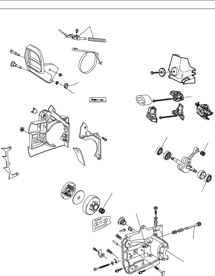
SERVICE DATA 334T/338XPT
15 |
2-3 |
20-26
Character key |
8-10 |
8-10 |
|
The numbers by bolted components represent the tightening torque in Nm.
▲ = Lubricate using two-stroke oil. ■ = Lubricate using engine oil.
● = Lubricate using grease.
= Glued using 2 component adhesive.= Sealed using silicone.
12 – English

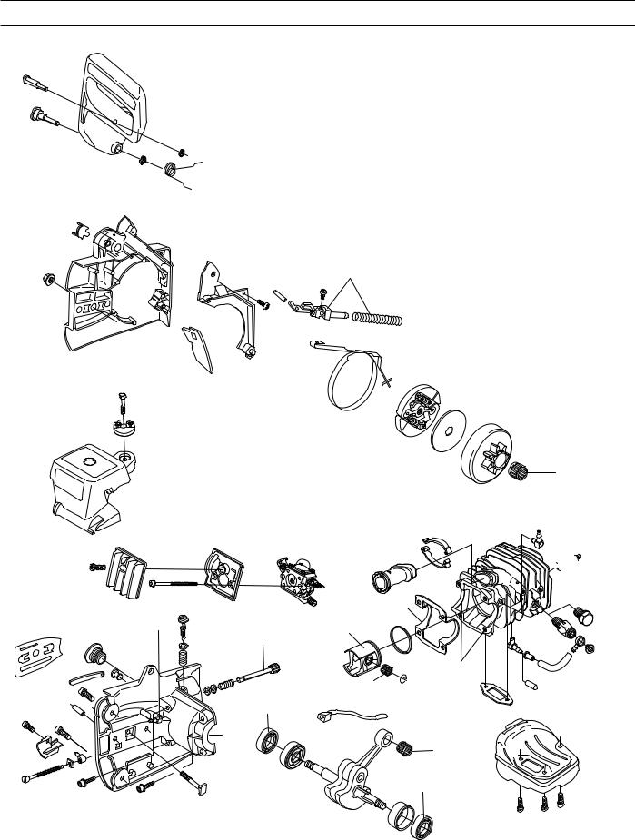
SERVICE DATA 334T/338XPT
2,5-4 |
1-2 |
2-3
8-10

 10-15
10-15
*
6-7 

 2-3
2-3
2-3


 2,5-4
2,5-4
 2,5-4
2,5-4
 20-26
20-26
English – 13
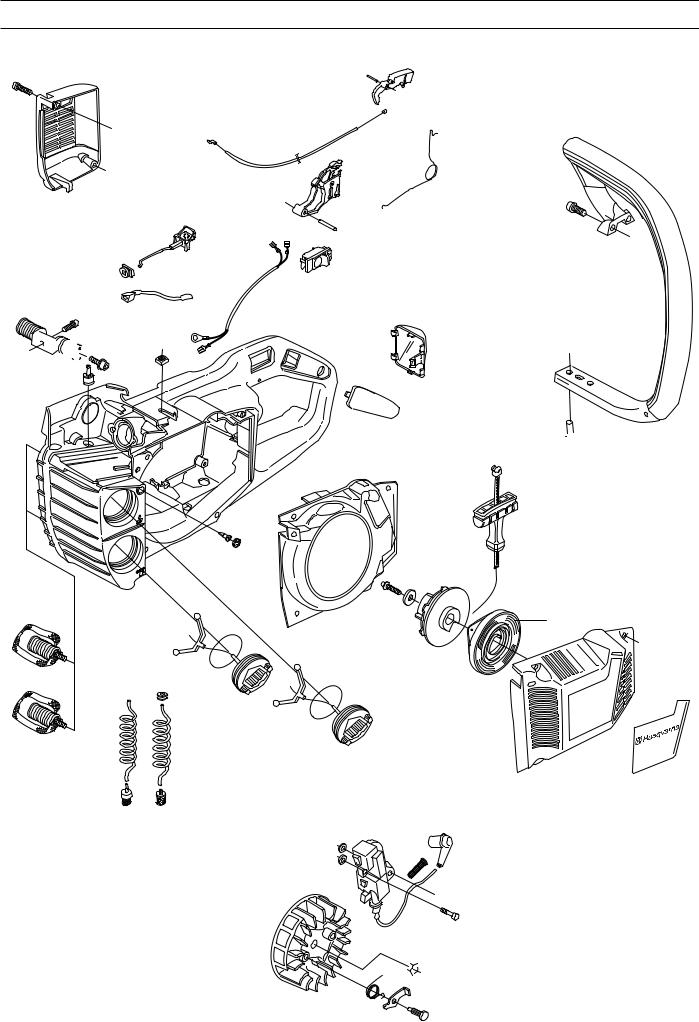
SERVICE DATA 336/339XP
15
20-26

 10-15
10-15
2-3
*
8-10 8-10
Character key |
8-10 |
The numbers by bolted components represent the tightening torque in Nm.
▲ = Lubricate using two-stroke oil. ■ = Lubricate using engine oil.
● = Lubricate using grease.
= Glued using 2 component adhesive.= Sealed using silicone.
14 – English
SERVICE DATA 336/339XP
2,5-4
P
O
T
S
6-7


 2-3
2-3
2-3


 2,5-4
2,5-4
 2,5-4
2,5-4
 20-26
20-26
English – 15
SAFETY EQUIPMENT
Chain brake
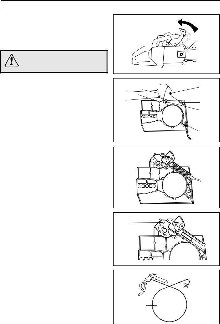
Dismantling
1.Check that the chain brake is off and dismantle the bolt (A) and the clutch cover.
WARNING!
Check that the brake is on. Otherwise the pressure spring can fly out and cause personal injury.
2.Remove the circlips (B) and (C) then push/knock out the pins.
3.Remove the handle.
4.Undo the four bolts (D) and remove the cover.
A
D
B |
|
C |
D |
|
|
|
D |
D
5.Remove the pressure spring by loosening the rear edge with a screwdriver.
6.Knock out the pin (E) and remove the knee joint with the attached brake band.
E
7. Unscrew the brake band from the knee joint.
Cleaning and inspection
Clean and inspect all parts. The thickness of the brake band must not be under 0.8 mm at any point.
16 – English
SAFETY EQUIPMENT
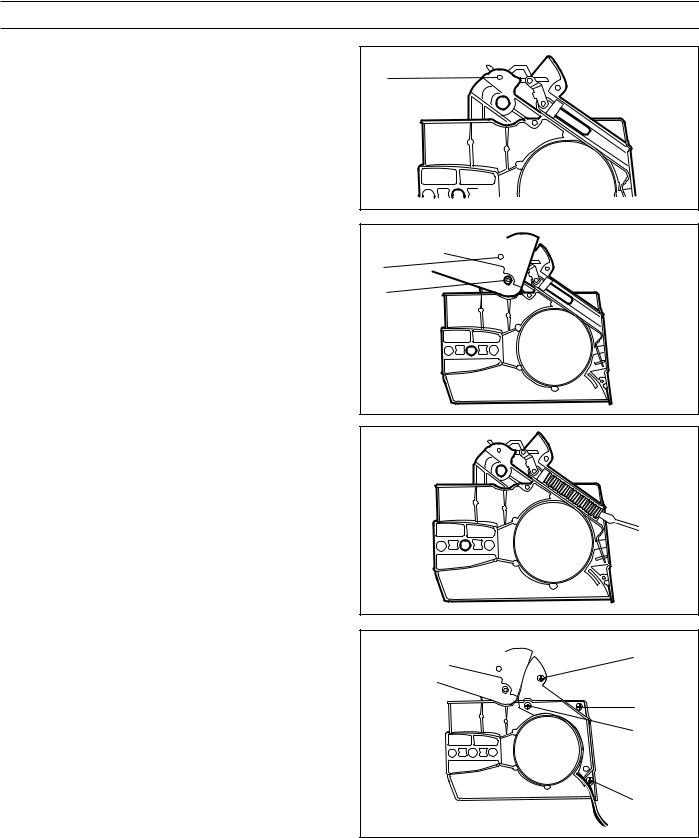
Assembly
Assemble the chain brake as follows:
E
1. Bolt together the knee joint and brake band.
2. Grease the knee joint’s moving parts and assemble the unit in the cover and knock in the pin (E).
3.Fit the kickback guard, insert the two pins and fit the circlips
(B) and (C).
B
C
4.Apply the brake and fit the spring. Use a screwdriver to press down the rear edge.
5.Fit the cover and tighten the four bolts (D).
6.Release the brake and fit the clutch cover on the chain saw. Adjust the chain tension, see the Operator Guide. Tighten the nut to 15 Nm.
D
D D
D
English – 17
SAFETY EQUIPMENT
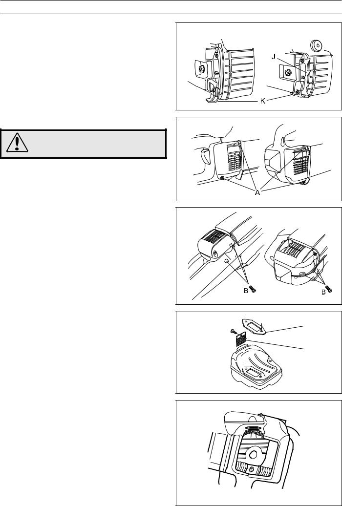
Chain catcher
Dismantle the chain and bar. See the Operator Guide. Check the spike (J), does not apply to 333, and the chain catcher (K). Replace any components if damaged. The bolts should be tightened to 4 Nm.
Assemble the chain and bar. See the Operator Guide.
Muffler
WARNING!
Do not touch the muffler until it has cooled.
Risk for burns.
Dismantling
Dismantle the muffler as follows:
1.Dismantle the muffler guard by removing the two bolts (A).
2.Turn the saw and undo the three bolts (B) holding the muffler.
3.Lift out the muffler to the side.
4.Remove the gasket.
Cleaning and inspection
Clean all components and check the following:
1.That the spark-arrester (C) is intact.
2.That the muffler and its mountings are not cracked or having any other defects.
3.That the gasket (D) is undamaged.
Assembly
1.Place the chain saw in the fixture (see service tools) or in a vice so that the muffler’s seating on the cylinder is horizontal.
2.Place the gasket (D) in position on the cylinder.
3.Carefully slide in the muffler without disturbing the gasket.
4.Press the muffler down on the cylinder once the bolt holes in the muffler, gasket and cylinder are aligned. The gasket can be adjusted using a small screwdriver.
5.Tighten the muffler bolts to 8-10 Nm.
6.Fit the muffler guard.
D
C
 D
D
18 – English
 Loading...