

Huntleigh Healthcare BABY DOPPLEX 4000, BABY DOPPLEX 4002 Service Manual
BABY DOPPLEX 4000®, BABY DOPPLEX 4002
CUSTOMER SUPPORT DOCUMENTATION
SERVICE MANUAL
Part number 614365
Issue 2, January 2000
Huntleigh Diagnostics Ltd
Service Dept
35 Portmanmoor Road
Cardiff UK. CF24 5HN
Tel: (029)20496793 (24 hrs)
Fax: (029)20492520
E-mail: service@huntleigh-diagnostics.co.uk
®
The information contained in this publication may not be used for any purpose other than that for which it was originally supplied.
The publication may not be reproduced in part or in whole without written consent.
Huntleigh Diagnostics Ltd products are subject to continuous development and consequently may incorporate minor changes from
the information contained in this manual.
The equipment and its accessories must be used strictly in accordance with the procedures detailed in this manual. The
manufacturer and its subsidiaries cannot accept any liability for loss or any indirect or consequential damages resulting from
misuse of, or modification to, the equipment or from operator negligence.
®Dopplex and 'H' logo are registered trade marks of Huntleigh Technology PLC
©Huntleigh Technology PLC 2000

614365
Table of Contents
1 General Information .............................1
1.1 Introduction ..............................1
1.2 Servicing Policy ............................1
1.3 Product Description ..........................1
1.4 Antistatic Handling, Electro Static Discharge (ESD) ..........2
1.5 Construction ..............................2
2 Safety Aspects ................................3
2.1 Safety .................................3
2.2 Safety Testing .............................3
2.3 FECG Testing .............................4
2.4 Cleaning
2.5 Preventative Maintenance .......................6
2.6 CE marking...............................6
3 Functional Testing ..............................7
3.1 BD4000, BD4002 Main Unit ......................7
3.2 Ultrasound Transducers ........................7
3.3Toco..................................8
3.4 FECG Functional Testing........................9
3.5 Twins Functional Testing - BD4000 ..................9
3.6 Twins Functional Testing - BD4002 ..................11
4 Specification.................................12
5 Technical Description............................14
5.1 The Doppler Principle.........................14
5.2 Doppler Audio Processing ......................14
5.3 Heart Rate Processing ........................15
................................5
5.4 Fetal Movement Detection (FMD) ..................15
5.5 FECG .................................15
5.6IUP..................................15
6 BD4000 overview ..............................16
6.1 BD4000 Micro Section ........................17
6.2 BD4000 Analogue Section
6.3 BD4000 Power Supply Section ....................20
......................18
Issue: 2 DRAFT i
Rev: a

614365
6.4 BD4000 Printer Section........................21
6.5 BD4000 Rear Panel Section
6.6 BD4000 Front Panel PCB.......................23
7 BD4002 overview ..............................24
7.1 BD4002 Micro Section ........................25
7.2 BD4002 Analogue Section
7.3 BD4002 Power Supply Section ....................28
7.4 BD4002 Printer Section........................29
7.5 BD4002 Rear Panel Section
7.6 BD4002 Front Panel PCB.......................31
8 BD4000/BD4002 Transducers .......................32
8.1 US1 Ultrasound Transducer .....................32
8.2 FECG Leg Plate ...........................33
8.3 IUP Module ..............................34
9 Electrostatic Discharge (ESD) Precautions ................35
9.1 What is Static Electricity? .......................35
.....................22
......................26
.....................30
9.2 Protective Measures .........................35
10 Servicing Procedures - Main Unit.....................36
10.1 Torque Settings ...........................36
10.2 Unit Dismantling ..........................37
10.3 Unit Reassembly ..........................37
10.4 Display/Front Panel Switch PCBs Removal .............37
10.5 Display PCBs Refitting .......................37
10.6 Display PCB Metalwork Removal ..................38
10.7 Refitting Display PCB Metalwork ..................39
10.8 Main PCB Removal .........................40
10.9 Main PCB Refitting .........................40
10.10 Print Head Removal ........................40
10.11 Print Head Refitting.........................41
10.12 Print Head Alignment Procedure ..................41
10.13 Stepper Motor Removal ......................42
10.14 Stepper Motor Refitting.......................42
10.15 Power Supply Removal ......................44
10.16 Power Supply Refitting .......................44
ii Issue: 2 Draft
Rev: a
614365
10.17 Mains Inlet Removal ........................44
10.18 Mains Inlet Refitting ........................44
10.19 Speaker Removal .........................45
10.20 Speaker Refitting ..........................45
10.21 Rear Panel Connector PCB Removal ...............45
10.22 Rear Panel Connector PCB Refitting ...............45
10.23 Paper Tray Open Microswitch Removal ..............46
10.24 Paper Tray Open Microswitch Refitting ..............46
10.25 Paper Tray Removal ........................46
10.26 Paper Tray Refitting ........................47
10.27 Paper Width Microswitch Removal.................47
10.28 Paper Width Microswitch Refitting .................47
10.29 Front Panel Connector Assembly Removal ............47
10.30 Front Panel Connector Assembly refitting .............47
10.31 Toco/Ultrasound Transducer Dismantling .............47
10.32 Reassembly of Toco/Ultrasound Transducer............48
10.33 Strain Gauge Assembly Removal .................48
10.34 Strain Gauge Assembly Refitting..................48
10.35 Toco Transducer Alignment ....................49
10.36 Replacing Transducer Cable ....................52
10.37 FECG Transducer Servicing ....................53
11 Fault Finding ................................53
11.1 Error Codes .............................55
11.2 Service Notes ............................56
11.3 Displaying Status ..........................56
11.4 Print Head Test ...........................57
11.5 Bed number .............................57
11.6 Real time clock battery .......................57
11.7 Address ...............................57
12 Spare Parts List ..............................58
12.1 Recommended Spare Parts .....................58
13 Warranty And Service ...........................70
14 Overseas Offices..............................71
15 Appendices.................................72
Issue: 2 DRAFT iii
Rev: a

614365
15.1
15.2 Appendix B .............................73
Appendix A
.............................72
iv Issue: 2 Draft
Rev: a

614365
1 General Information
1.1 Introduction
This service manual provides the technical information required for repair and
maintenance of the Huntleigh Diagnostics Baby Dopplex 4000 and Baby Dopplex
4002.
1.2 Servicing Policy
Due to the nature of static-sensitive surface-mount technology, specialised equipment
and training is required when working on the surface mounted components used within
this product.
For this reason circuit diagrams are not included in this manual. Block diagrams and
fault finding sections are included to make fault finding to leaded component level
possible.
Units within the warranty period must not be dismantled and should be returned to
Huntleigh Diagnostics for repair. Any units returned showing signs of tampering or
accidental damage will not be covered under the warranty (refer to user manual for
further details).
1.3 Product Description
General
The Baby Dopplex 4000 and Baby Dopplex 4002 comprise a main unit (which
can be either free-standing, trolley or wall-mounted), two transducers (US* and
Toco). A patient event marker and a FECG legplate (optional). *BD4002 is
supplied with 2 US transducers.
Main Unit
This houses the printer and electronic circuitry - digital and analogue signal
processing, audio, display and power supply systems.
Signals from the transducers are processed and displayed on the large LED
displays. The ultrasound signal is also amplified, and output via the integral
loudspeaker. A volume control provides adjustment of sound level as required.
Processing for the FECG signal is also included.
A liquid crystal display (LCD) displays the system menu and other
information. Various parameters can be selected and/or changed as necessary
using the adjacent controls.
Also mounted on the control panel are controls for volume up/down, print
start/stop, Toco zero and clinical event marker.
Issue: 2 DRAFT 1
Rev: a

614365
Transducers
The transducer connectors are colour coded to indicate function: the
US/FECG connector is red, the Toco connector is blue.
The transducers are held in place by elasticated straps.
Patient Event Marker
This is a hand-held push-button which is pressed by the patient when she
feels fetal or uterine activity.
F
1.4 Antistatic Handling, Electro Static Discharge (ESD)
The Baby Dopplex uses Electrostatic Discharge Sensitive Devices (ESD's) in its
manufacture. The damage they suffer when handled incorrectly may be catastrophic.
More often and potentially even worse, the damage may be partial or latent, seriously
impairing the reliability of the unit.
Due to the nature of the components used within the Baby Dopplex, special
precautions must be taken to avoid damage to the circuitry. Static damage may not
be immediately evident but could cause premature failure.
The Baby Dopplex must only be dismantled and serviced within an ESD protected
area (EPA) as defined by CECC00015 (published by CENELEC) to avoid damage to
the assemblies.
1.5 Construction
The patient and clinical event markers are distinguished from each
other on the paper, patient at the bottom of the FHR grid and
clinical at the top.
The main unit comprises five PCB's, the main PCB, display PCB, PSU, end of paper
PCB and rear panel connector PCB. All boards with the exception of the PSU are
populated with surface mounted components.
The toco transducer consists of a termination PCB and a strain gauge.
The ultrasound transducer contains a single PCB, a multi element piezo crystal array
and a circular termination PCB.
The FECG transducer contains a single PCB and isolation amplifier with two scalp
electrode connections and a legplate disk for a maternal connection.
All electromechanical and through hole components are serviceable using standard
tools and soldering techniques, provided that anti-static precautions are always taken.
Recommended servicing is limited to replacement of assemblies detailed in this
manual.
2 Issue: 2 Draft
Rev: a

614365
2 Safety Aspects
2.1 Safety
The Baby Dopplex and its transducers are designed to high standards of
q
performance, reliability and safety.
Functional and safety checks should always be made after carrying out any
q
repairs or dismantling the equipment.
It is recommended that regular inspections are to be made to check the integrity of the
unit, and to ensure cables are not showing any signs of wear or noise when flexed.
2.2 Safety Testing
Using suitable safety test equipment, refer to the following guidelines.
Earth Bonding Test points
a) Test the exposed chassis, accessible through the moulding apertures on the
underside of the unit.
b) Test the metal shroud of the toco socket.
c) Test the shells of the rear panel D-type connectors.
The maximum allowable reading at all points is 0.1W .
Earth Leakage Test
Set the on/off switch on the rear of the unit to the on position.
The maximum allowable leakage current is 100 m A.
Breakdown Test
Set the on/off switch on the rear of the unit to the “on” position.
Apply 1500Vac to the mains connector, connecting the low voltage probe to the
“EARTH” terminal. Firstly test the “LIVE” terminal and then the “NEUTRAL” for 60
seconds each. The maximum allowable reading is 1mA.
Issue: 2 DRAFT 3
Rev: a

614365
2.3 FECG Testing
Apply 1500Vac between the;
a) chassis earth and leg electrode plate
b) instrument live terminal and FECG terminals
c) instrument neutral terminal and FECG terminals
The maximum allowable reading being 10m A over 60 secs.
Caution
Do not apply test voltages to main unit FECG input socket directly
If you require any assistance with safety testing your Huntleigh Diagnostics
equipment, contact Huntleigh Diagnostics. For the U.K. refer to the Health
Equipment Information Document No 95 – Code Of Practice For Acceptance Testing
Of Medical Equipment.
The following safety summary should be read before operating or carrying out any of
the procedures described in this manual:
Cautions
q
Do not use the Baby Dopplex in the presence of flammable gases such as
anaesthetic agents.
q
This product is not designed for sterile use. Do not use in the sterile field unless
additional barrier precautions are taken.
Do not - immerse main unit in any liquid. See section 2.4.
- use solvent cleaners.
- use high temperature sterilising processes (such as autoclaving).
- use E-beam or gamma radiation sterilisation.
4 Issue: 2 Draft
Rev: a

614365
2.4 Cleaning
Caution
Switch the unit off and disconnect from the mains before cleaning
Main Unit If required, this can be wiped with a soft cloth dampened with a
mild detergent, avoiding the connectors. Do not allow any fluid
to seep into the connectors. Do not allow any fluid to seep into
the unit.
Ensure the unit is completely dry before reconnecting to the
mains.
Ultrasound
Transducer
and FECG
Leg Plate
These should be cleaned by immersing in warm (50
detergent solution, using a bottle brush if necessary. Do not
soak,or run under a tap. Rinse with clean water and dry
thoroughly before use.
Do NOT immerse connectors
o
C max.), mild
F
Caution
Phenolic or detergent based disinfectants containing cationic
surfactants, ammonia based compounds, or antiseptic solutions such as
Stericol or Hibiscrub should never be used on any part of the system as
permanent damage will result.
Contractions
Transducer
(toco)
Belts These may be hand-washed at 40
Wipe with a soft cloth dampened with a mild detergent solution,
avoiding the connector. Do not allow any fluid to seep into the
transducer. Dry thoroughly before use.
o
C max., using a mild detergent
solution. Rinse with clean water and dry thoroughly (without using
heat) before use.
Disinfection Transducers and Leg Plate Only.
To assist with disinfection, wipe the transducers and leg plate
with a soft cloth dampened with sodium hypochlorite 1000ppm,
and wipe dry.
Please be sure to check your local infection control policies or
equipment cleaning procedures.
Issue: 2 DRAFT 5
Rev: a

614365
2.5 Preventative Maintenance
The Huntleigh Diagnostics Baby Dopplex 4000 and Baby Dopplex 4002 are
designed for a minimum amount of maintenance. To support the high standard of
performance and safety, the safety and functional checks should be carried out as part
of a regular maintenance routine.
Refer to the user manual for details of connection of cables and accessories, and also
for the correct setting of controls which may have been altered during maintenance.
No attempt should be made to service the unit unless adequate workshop facilities
and suitable staff are available.
2.6 CE marking
All rework procedures detailed in this service manual must be strictly adhered to, to
ensure continuing compliance with EC Directive 93/42/EEC.
Any rework routine carried out outside the scope of this manual may result in the
equipment no longer meeting this specification and the rework organisation will be
responsible for this non-conformance.
6 Issue: 2 Draft
Rev: a

614365
3 Functional Testing
3.1 BD4000, BD4002 Main Unit
Switch the unit on by pressing the on/off switch at the back of the unit to the “on”
position(I).
The Baby Dopplex displays will illuminate and you will hear a click from the
loudspeaker. The message “Huntleigh Diagnostics” appears for an instant while the
unit carries out a self-test.
Inspect the transducer cables and plugs for signs of damage and physical condition of
the transducers.
The ultrasound transducer face should be free from marks and the toco boot
undamaged. Remove any gel from the transducers if present.
Open printer tray, unit should display “Paper tray open” and remove paper pack.
Close paper tray, unit should display “End of paper”. Refit paper pack ensuring that the
shiny side is uppermost. This sensitive side can be easily marked with a fingernail.
Plug in the ultrasound, toco and event marker transducers, set the printer to 3cm/minute
(menu option) and start the unit printing.
Press the patient event marker switch and observe the arrow at the bottom of the
printout.
Press the clinical event marker on the display panel and an arrow should appear at the
top of the printout.
Increase the volume using the up/down controls on the front panel and flex cable on the
ultrasound transducer at the transducer and plug ends checking that no crackling is
heard.
Replace the ultrasound transducer with the FECG leg plate. The unit should fast feed
for a few seconds if the printer is still running when the ultrasound transducer is
removed, and then continue printing.
Ensure that the FECG text appears at the bottom of the FHR scale on the trace.
3.2 Ultrasound Transducers
Reconnect the ultrasound transducer and input a signal by placing it in the palm of the
hand and stroke the back of the hand approximately twice per second.
The display should indicate a rate of around 120 BPM after a few seconds. Continue
this for one minute and check for a corresponding line on the fetal heart rate trace.
F
Issue: 2 DRAFT 7
Rev: a
Too strong a signal from an adult heart can overload the unit and
result in false counting.
614365
The signal quality will vary during this test and can be observed in the top right hand
corner of the LCD display. The four bands are illuminated for a good signal and
progressively extinguish as the signal deteriorates. Repeat for FHR1 and FHR2
inputs using front panel to select audio channel (BD4002 only).
3.3 Toco
Place the toco transducer on a solid surface with the rubber boot uppermost and level.
Press the zero button on the front panel. Holding the toco transducer steady, flex the
cable at the transducer and plug ends. Check the UA loading display and printout to
ensure that there is no deviation from the zero line.
Depress the toco rubber boot gently and release, repeat this several times. Check that
the UA display registers the change and returns to zero after a short delay.
With the rubber boot still uppermost and level, reset the zero then place a 100g
weight in the centre of the boot.
The shape of this weight is important and the contact area on the rubber boot should
be 12mm diameter maximum. The UA display should indicate 80% +/-5%.
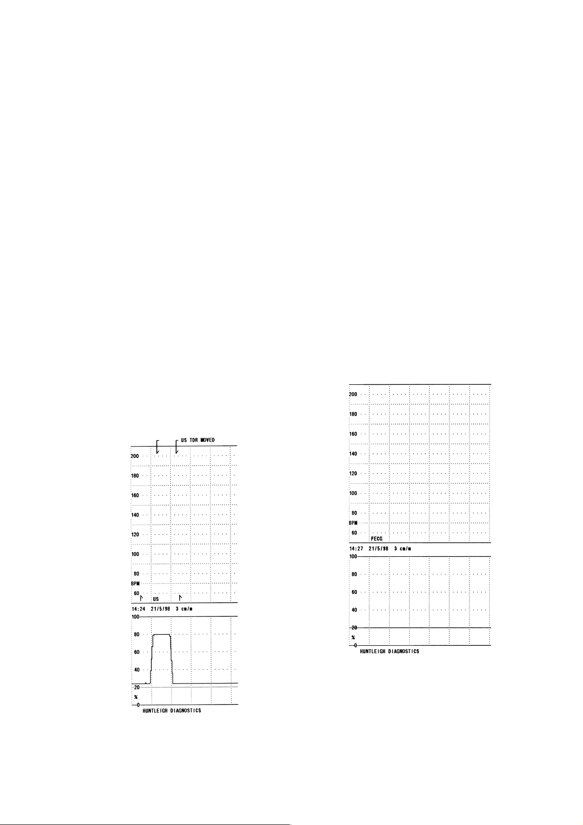
Ultrasound Mode
FECG Mode
8 Issue: 2 Draft
Rev: a

614365
Remove the weight after 30 seconds check for return to zero and turn the printer off, the
printer should fast feed a blank section.
Compare the printout with the examples shown above, checking for print quality,
date/time stamp, event markers, ultrasound, toco trace and mode (i.e. US/FECG).
3.4 FECG Functional Testing
Reconnect the FECG legplate. Connect the patient terminals to an Fetal ECG simulator
setting the voltage to between 25m V and 2mV. Only one FECG transducer can be used
at any one time. Use of an adult ECG simulator may cause erroneous readings.
The ECG rate should be set between 30-240 and checked across its range.
3.5 Twins Functional Testing - BD4000
Connect two BD4000 units together using the connection lead supplied with the twins
kit. The monitor with the cable end marked '1' causes the unit to be the LOCAL unit
while the other unit defaults to REMOTE.
The display on the LOCAL BD4000 should display “Remote FHR =” in the top line of
the text display.
Connect an ultrasound transducer to both units and input a signal on the REMOTE unit
by stroking the ultrasound transducer.
The REMOTE unit LCD should display 'Twins Remote Unit' and the printer should be
inoperative.
The FHR should be displayed on both the REMOTE LED and LOCAL LCD displays.
Set the printer on the LOCAL unit to print and with a signal to the REMOTE unit, a
corresponding trace should be printed.
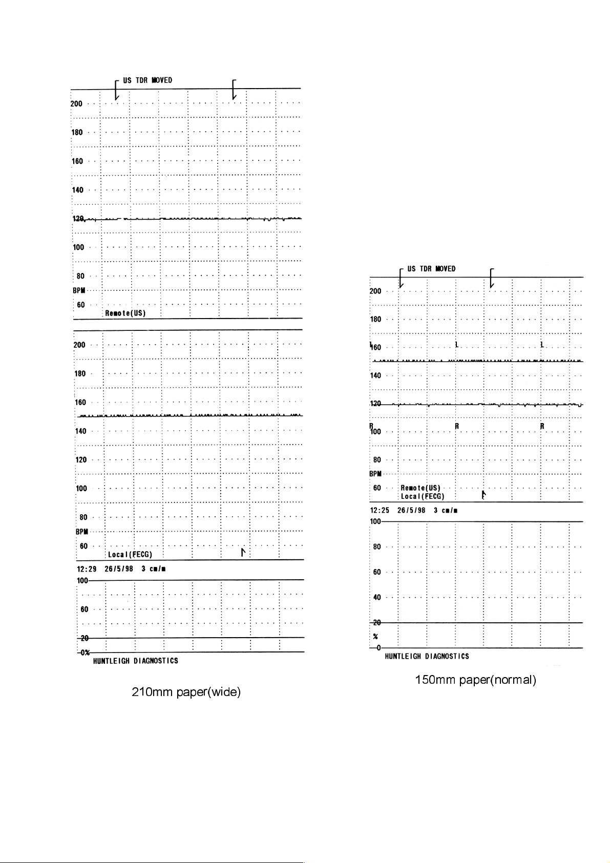
When full width paper(210mm) is loaded, the LOCAL unit will print two FHR grids
one above the other and one toco trace.
With the normal paper(150mm) fitted, the two FHR traces are overlaid on one grid, and
identified periodically by the letters 'R' and 'L'.
Issue: 2 DRAFT 9
Rev: a
614365
210mm paper(wide)
150mm paper(normal)
10 Issue: 2 Draft
Rev: a

614365
3.6 Twins Functional Testing - BD4002
Fit both US transducers and toco transducer and test as detailed in section 3.2.
Only one FECG transducer can be used at any one time and should be tested as detailed
in section 3.4.
When full width paper(210mm) is loaded, the unit will print two FHR grids one above
the other and one toco trace.
With the normal paper(150mm) fitted, the two FHR traces are overlaid on one grid, and
identified periodically.
Issue: 2 DRAFT 11
Rev: a

614365
4 Specification
General
Product Name: Baby Dopplex 4000/Baby Dopplex 4002
Model No: BD4000/BD4002
Physical
Size - control unit: 93mm x 380mm x 250mm (HxWxD)
Weight: 4.5Kg
Environmental
o
Operating Temperature: +10
Storage Temperature: -10
Electrical
Cto+30oC
o
Cto+40oC
Power Supply:100-250V a.c. 50/60Hz
Fuse Type: T2A 250V
Audio Power: 1 Watt max
Ultrasound Transducer
Transmitter frequency: US1 - 1.5MHz +/-1%
Acoustic Output: Under the requirements laid down in IEC1157:
1992, the peak negative acoustic pressure does
not exceed 1MPa. the output beam intensity
does not exceed 20mW/cm
2
and the
spatial-peak temporal-average intensity does not
exceed 100mW/cm
2
.
Contractions Transducer
Range: 0 to 100% relative units.
Max. Load: 300g.
Regulatory Compliance/Standards
Complies with: BS5724 : Part 1 : 1989
IEC601-1 : 1988
EN60601-1 : 1990
12 Issue: 2 Draft
Rev: a

614365
EN60601-1 Classification: Type of shock protection - Class I
Degree of shock protection - Type B
Leg Plate & IUP Module Type BF
Protection Against Ordinary equipment
Water Ingress
Degree of Safety in PresenceNot suitable for use in the presence of
of Flammable Gases: flammable gases.
Mode of Operation: Continuous
Performance
FHR Range: US 50 to 210 BPM
FECG 30 to 240 BPM
FHR Accuracy: +/- 1BPM over full range.
FHR Scale Options: 50 to 210 BPM at 20 BPM/cm,
30 to 240 BPM at 30 BPM/cm.
Medical Devices Directive 93/42/EEC
Issue: 2 DRAFT 13
Rev: a

614365
5 Technical Description
5.1 The Doppler Principle
The Baby Dopplex uses the Doppler principle for non-invasively monitoring
movement within the body.
The Doppler principle states that if a signal is transmitted at a fixed frequency and is
reflected by a moving body, the frequency of the received signal will be shifted. An
increase in frequency results if the reflector is moving towards the
transmitter/receiver, and a decrease results if moving away from the
transmitter/receiver. The amount of frequency shift is proportional to the velocity of
the reflector relative to the transmitter/receiver.
In the Dopplex range, a fixed frequency ultrasonic signal is transmitted from the
transducer into the body. This is reflected from, for example, the fetal heart. The
signal is reflected from the heart and is received by the transducer. Due to the
movement of the fetal heart, a frequency shift results, which is proportional to the
fetal heart velocity.
5.2 Doppler Audio Processing
The Baby Dopplex ultrasound transducer contains a transmitter and receiver. In use,
the transducer sends out a pulsed ultrasonic signal, generated by the piezo-ceramic
transmitter crystals, at 1.5 MHz.
This signal is scattered by blood cells or any other “interface” such as skin, muscle
layers, organs, walls of vessels etc. A small proportion of the scattered signal will be
reflected back and detected by the receiver.
By demodulating the received signal (removing the high frequency carrier) the
Doppler shifted component (i.e. the difference between the transmitted and received
signals) can be produced.
With typical target velocities found in the human body, this Doppler shift signal falls
within the audio frequency range. It can therefore simply be amplified and heard
through a loudspeaker.
It is important to remember that the sound you hear is an artificial sound, the
frequency (pitch) of which is proportional to the velocity of the moving target.
It is not the real sound made by the fetal heart.
14 Issue: 2 Draft
Rev: a

614365
5.3 Heart Rate Processing
The Doppler audio signal is amplified and filtered. It's amplitude is then regulated after
passing through a low-pass anti-aliasing filter. The signal is then sampled by the
microcontroller in order to calculate the fetal heart rate.
5.4 Fetal Movement Detection (FMD)
The BD4000 and BD4002 will annotate the fetal heart trace towards the top of the
contraction channel when a fetal movement is detected.
This movement is derived from low frequency Doppler signals from the Ultrasound
Transducer.
The FMD can be enabled via the front panel and its sensitivity set.
Refer to the user manual for further information.
5.5 FECG
As an alternative to using ultrasound to monitor FHR, a FECG scalp electrode may be
used.
This makes a direct connection to the fetal scalp and provides more reliable tracking of
the fetal heart rate during the later stages of labour.
The FECG transducer incorporates an isolation amplifier which provides electrical
isolation between the patient and the monitor.
5.6 IUP
In some markets Intra Uterine Pressure measurements are made as an alternative to the
external Toco transducer supplied as standard.
Patient electrical isolation is provided by an adaptor box plugged into the Toco socket
and a corresponding waveform is printed on the contractions trace either shown in
millimetres of Mercury (mmHg) or kiloPascals (kPa).
The pressure sensor is either inserted directly into the mother using the Intran Plus IUP
400 Disposable IUP System (Utah Medical Products inc). Alternatively using the
SensoNor SP844 pressure sensor and a saline filled catheter system. Refer to user
manual for further information.
Issue: 2 DRAFT 15
Rev: a

614365
6 BD4000 overview
The BD4000 has been split up into several sections as shown below for clarity.
16 Issue: 2 Draft
Rev: a
614365
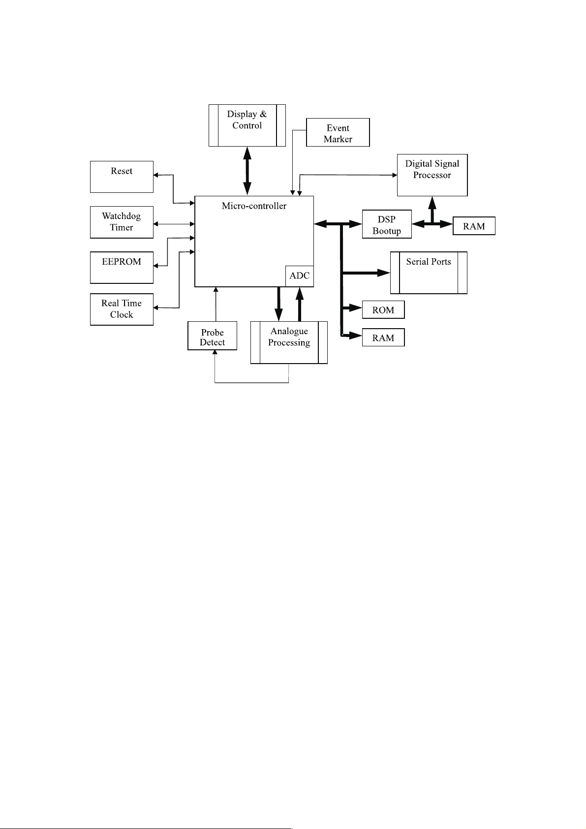
6.1 BD4000 Micro Section
Real Time Clock, this enables the micro to display and print the date/time on
the trace. User setup information is held within the internal memory of the
clock.
Watchdog Timer, this monitors the micro and checks for any system errors.
Upon detecting a system error the micro is reset. All controls revert to
switch-on settings.
Event Marker, this patient event marker records a mark on the printout in a
different place from the clinical event marker accessed via the front panel (see
user manual).
Serial Ports, the rear connector PCB supports two D-type RS232 connectors
for external interfacing and twins mode communication.
Display PCB, is mounted on the top half of the case moulding and consists of
two separate PCBs joined by a short ribbon cable. This PCB also carries the
system controls.
ROM, the ROM memory contains the program.
RAM, the main PCB has three RAM IC's, two are used on the Digital Signal
Processing section and the third for data processing by the micro.
Digital Signal Processor, processes the information from the ultrasound and
ECG transducers implementing autocorrelation and ECG detection for deriving
the FHR.
Issue: 2 DRAFT 17
Rev: a

614365
DSP Bootup, this circuitry loads the DSP program from EPROM to the DSP’s
internal RAM when the unit is reset.
EEPROM, used for storage of user setup information when the unit is switched off.
Twins Detect, a link in the cable sets the monitor to twins mode.
18 Issue: 2 Draft
Rev: a
 Loading...