


41652_model44760_web.pmd
1

 ® Auto Temp Heat Pump Thermostat
Owner’s Manual |
Model 44760 |

41652_model44760_web.pmd
2
Introduction |
|
2 |
CONGRATULATIONS! |
|
|
Your new Hunter electronic thermostat will provide years of |
Please read this manual for complete instructions on installing |
|
reliable service. By saving energy, your thermostat will pay for |
and operating your thermostat. |
|
itself during its first season of use. Thank you for buying a |
If you require further assistance, call Hunter Support at 888- |
|
Hunter product! |
|
|
|
830-1326 from 8 AM to 5 PM Central Time. |
|
|
|
|
Model Information: |
|
|
Model Number |
44760 |
|
Serial Number____________________________________________ |
||
Date Purchased |
__________________________________________ |
|
Where Purchased _________________________________________
3
Table of Contents |
|
3 |
INTRODUCTION |
Read This Before Installing Thermostat |
6 |
|
Features |
8 |
INSTALLATION |
What You Need |
10 |
|
Remove Old Thermostat |
10 |
|
Wire Labeling |
11 |
|
Mount Wallplate and Thermostat |
14 |
|
Connect Wires and Mount Thermostat to Wallplate |
15 |
PROGRAMMING |
Option Menu |
16 |
|
Setting Time and Day |
18 |
|
12 Hr. / 24 Hr. Time Format |
19 |
|
Programming Introduction |
20 |
|
Personal Program Schedule |
21 |
|
Programming |
23 |
|
Weekday/Weekend Programming |
24 |
|
7-Day Programming |
26 |
|
Everyday Programming |
28 |
(continued)
41652_model44760_web.pmd
4
|
|
Table of Contents (continued) |
4 |
|
||
|
|
|
||||
|
|
PROGRAMMING (continued) |
Program Options |
30 |
|
|
|
|
|
Programmable Fan |
30 |
|
|
|
|
|
Reviewing Programs |
30 |
|
|
|
|
OPERATIONS |
Power Switch |
32 |
|
|
|
|
|
System Selection Key |
32 |
|
|
|
|
|
Fan Key |
33 |
|
|
|
|
|
System Indicator Light |
34 |
|
|
|
|
|
Emergency Heat |
35 |
|
|
|
|
|
Reviewing the Current Temperature Setting |
35 |
|
|
|
|
|
Temporary Manual Override |
36 |
|
|
|
|
|
Permanent Manual Override |
37 |
|
|
|
|
|
Vacation (Programmable) Hold |
38 |
|
|
|
|
|
Auto Season Changeover |
39 |
|
|
|
|
|
Home Today |
40 |
|
|
|
|
|
Energy Monitor |
42 |
|
|
|
|
|
Filter Monitor |
43 |
|
|
|
|
|
SPAN Settings |
44 |
|
|
|
|
|
|
|
|
|
|
|
|
|
|
|
|
5
|
OPERATIONS (continued) |
Auto Recovery |
45 |
|
|
|
|
|
|||
|
|
Keyboard Lock |
46 |
|
|
|
|
Backlighting (INDIGLO® Night-Light) |
47 |
|
|
|
SAFETY FEATURES |
AC Power Monitor |
48 |
|
|
|
|
Low Battery Warning |
48 |
|
|
|
|
Error Mode |
49 |
|
|
|
TROUBLESHOOTING |
Problems & Solution |
50 |
|
|
|
|
Technical Support |
51 |
|
|
|
WIRING DIAGRAM |
Heat Pump Systems |
52 |
|
|
|
|
|
|
|
|
|
|
|
|
|
|
41652_model44760_web.pmd
6
|
|
Read This Before Installing Thermostat |
6 |
|
|
|
|
|
|||
|
|
IMPORTANT |
SYSTEM COMPATIBILITY |
|
|
|
|
Read the entire installation section of this Owner’s Manual |
Your Thermostat is designed to operate these |
|
|
|
|
1thoroughly before you begin to install or operate your |
424-Volt systems: |
|
|
|
|
Hunter Thermostat. |
■ Multi-stage heat pumps with auxiliary heat |
|
|
|
|
Remove the Mylar label from the LCD display window. |
|
||
|
|
■ Single-stage heat pumps |
|
||
|
|
|
|
||
|
|
INSTALLATION |
This thermostat will not control 120/240 Volt systems or |
|
|
|
|
All installation is normally performed at your |
millivolt systems. |
|
|
|
|
2thermostat. |
COMPRESSOR PROTECTION |
|
|
|
|
ARMCHAIR PROGRAMMING |
The thermostat provides a 3.5 minute delay after shutting off |
|
|
|
|
You can program your thermostat before installation by in- |
5the heating or cooling system before it can be restarted. |
|
|
|
|
3serting the batteries and following the instructions starting |
This feature will prevent damage to your compressor caused |
|
|
|
|
by rapid cycling. |
|
||
|
|
on page 16. This can be done while you relax in your favorite |
|
||
|
|
chair and is a very good way to familiarize yourself with all the |
|
|
|
|
|
functions of your Hunter Thermostat. |
|
|
|
|
|
|
|
|
|
|
|
|
|
|
|
7
|
TEMPERATURE RANGE |
BATTERY WARNING |
|
|
|
||
|
Your thermostat can be programmed between 45°F and 95°F |
Fresh alkaline batteries will provide over one year of memory |
|
|
6(7°C and 35°C). However, it will display room temperatures |
9backup and clock operation. However, when the batteries |
|
|
from 15°F to 99°F (-9°C and 37°C). “HI” will be displayed if the |
become drained, a low battery warning will appear on the dis- |
|
|
temperature is higher than 99°F (37°C), and “LO” will be dis- |
play. When this message occurs, install 2 new AAA batteries. You |
|
|
played if the temperature is lower than 15°F (-9°C). |
have approximately 30 seconds when changing the batteries to |
|
|
AUTO RECOVERY |
keep thermostat’s clock and program settings. |
|
|
NOTE: The default system selection at power-on is HEAT. |
|
|
|
Your thermostat is set from the factory to gradually recover |
|
|
|
Batteries are recommended to prevent an undesired sys- |
|
|
|
7the room temperature from an energy saving program to |
|
|
|
tem change due to a power outage. |
|
|
|
your comfort program. Therefore, the thermostat may turn your |
|
|
|
system on several minutes prior to your programmed time. This |
|
|
|
operation is normal, but can be turned off. Refer to the Options |
|
|
|
Menu information on pages 16. |
|
|
|
OPERATION |
|
|
|
This system operates on your system’s 24 Volt power supply. |
|
|
|
8The supply is monitored by the thermostat, and it will stop |
|
|
|
functioning if AC power is lost. (When using backup batteries, |
|
|
|
“No AC Pwr” will be displayed.) All system controls will remain |
|
|
|
off until power is restored. |
|
|
|
NOTE: The INDIGLO® Night-Light will not function when |
|
|
|
AC power is lost. |
|
|
|
|
|
|
|
|
|
|
41652_model44760_web.pmd
8
Features |
8 |
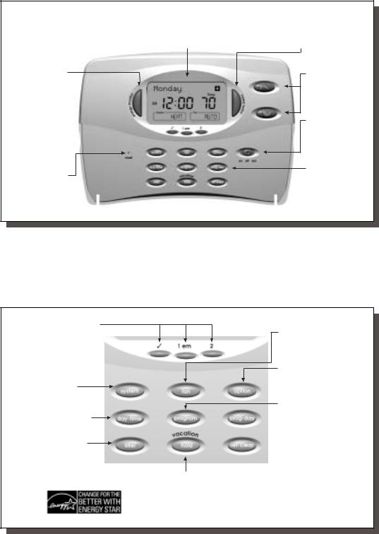
INDIGLO® Night-Light activated by pressing any key.
Energy Monitor:
Measures and displays heating and cooling system operating time for Today, Yesterday, This Month, Last Month, or Total. By monitoring your energy usage, you can program the thermostat to optimize energy savings.
Reset: Press with a paper clip to reset the thermostat and return to power-up settings.
Alpha-numeric display shows time, day, temperature, |
Home Today: Overrides energy-saving program |
program number, and other feature information as required. |
temperatures while you are at home for the day. |
Temperature Keys:
Keys for raising or lowering temperature
settings.
Power Switch:
Select ON, Positive
OFF, or Emergency
Heat.
Soft-touch programming keypad, see details below.
9
System Indicator LEDs: Show status of Stage 1, Emergency, Stage 2, and Check System.
System Key: Use to select system.
Select Heat, Cool or Auto.
Day/Time Key: Used for entering the Clock setting mode. Use with the Up and Down keys to set the time and day.
Filter: Displays the filter usage counter in hours and minutes.
Fan Key: Used to select fan mode.
Select Auto, ON, or Program
Controlled.
Option Key: Enters the option menu.
Program Key: Enters Program
Mode for reviewing or chaning
Weekday, Weekend, Daily or
Everyday programs.
 Program-Day Key: Selects the day or days to review or change in Program Mode.
 Return-Clear Key: Returns to normal display mode. Also clears Filter and Energy counters, and HOLD modes.
Vacation / Hold: Enters permanent and vacation (Programmable) HOLD modes.
As an ENERGY STAR® Partner, Hunter Fan Company has determined that this programmable thermostat meets the ENERGY STAR® guidelines for energy efficiency.
41652_model44760_web.pmd
10
INSTALLATION |
10 |
What You Need
This thermostat includes two #8 slotted screws and two wall anchors for mounting. To install your thermostat, you should have the following tools and materials.
■Slotted Screwdriver(s) ■ Electric drill and 3/16" bit
■Phillips Screwdriver ■ Two 1.5 V (AA) size alkaline batteries
■Hammer
Remove Old Thermostat
CAUTION: Do not remove any wiring from existing thermostat before reading the instructions carefully. WIRES MUST BE LABELED PRIOR TO REMOVAL.
■IMPORTANT! Turn off the power to the furnace at the main power panel or at the furnace.
■Remove existing thermostat cover. See Figure 1. Some thermostats will have screws or other locking devices that must first be removed. Once wall mounting plate is exposed, look for wires.
If wires are not visible, they may be connected to the back of the wallplate. Again, look for screws, tabs, etc. Some models have doors that open to expose wires and mounting screws. (See Figure 1).
TYPICAL HOME THERMOSTATS
Figure 1
Wall Mounting Plate |
Thermostat |
Cover |
Wall Mounting Plate |
Thermostat |
Cover |
11
|
|
Wire Labeling |
11 |
|
|
||||
|
|
|
|
||||||
|
|
■ Each wire coming from the wall to the existing thermostat is |
SHOWN IN TABLE A and B ON PAGES 12-13. (For example, |
|
|||||
|
|
connected to a terminal point on that thermostat. Each of |
attach the label marked W to the wire that goes to the W or H |
|
|||||
|
|
these terminal points is usually marked with a code letter as |
terminal on your existing thermostat.) IGNORE THE COLOR OF |
|
|||||
|
|
shown in Table A on the next page. |
THE WIRES since these do not always comply with the standard. |
|
|||||
|
|
■ The number of wires in your system can be as few as four |
■ After labeling wires, disconnect them from the existing ther- |
|
|||||
|
|
(for single-stage systems), as many as eight, or any number |
mostat terminals. |
|
|||||
|
|
in between. If you follow the labeling procedures correctly, |
■ Remove existing wallplate. To make sure wires do not fall back |
|
|||||
|
|
you do not have to be concerned about how many wires |
into wall opening, you may want to tape them to the wall. |
|
|||||
|
|
there are. |
|
||||||
|
|
■ If hole in wall is larger than necessary for wires, seal this hole |
|
||||||
|
|
■ IMPORTANT! BEFORE DISCONNECTING ANY WIRES, APPLY |
|
||||||
|
|
so that no hot or cold air can enter the back of the thermostat |
|
||||||
|
|
|
|
|
|
|
|
||
|
|
THE SELF-ADHESIVE LABELS PROVIDED TO THE WIRE AS |
|
||||||
|
|
from the wall. This air could cause a false thermostat reading. |
|
||||||
|
|
|
|
|
|
|
(continued) |
|
|
|
|
|
|
|
|
|
|
|
|
|
|
|
|
|
|
|
|
|
|

41652_model44760_web.pmd
12
|
|
INSTALLATION |
12 |
|
||
|
|
|
||||
|
|
|
|
|
|
|
|
|
|
|
TABLE A – TERMINAL DESCRIPTIONS |
|
|
|
|
|
|
|
|
|
|
|
TERMINAL |
FUNCTION |
|
|
|
|
|
LABELS |
(HEAT PUMP) |
COMMENTS |
|
|
|
|
R |
24V AC supply |
Hot wire of 24VAC transformer. Powers the thermostat & system. |
|
|
|
|
|
|
|
|
|
|
|
Y1 |
Compressor stage 1 |
Activates the 1st stage compressor. (Heat or Cool for Heat Pumps) |
|
|
|
|
|
|
|
|
|
|
|
W2 |
Auxiliary heating |
Activates the 2nd stage (auxiliary) heating when required. |
|
|
|
|
|
|
|
|
|
|
|
E |
Emergency heating |
Activates Emergency heating ONLY when the System Switch is in Emergency (em) Mode. |
|
|
|
|
|
|
|
|
|
|
|
O |
Reversing valve |
Activates reversing valve in COOL mode. ALWAYS ON in COOL MODE. |
|
|
|
|
|
(cooling mode) |
|
|
|
|
|
|
|
|
|
|
|
|
B |
Reversing valve |
Activates reversing valve in HEAT mode. ALWAYS ON in HEAT MODE. |
|
|
|
|
|
(heating mode) |
|
|
|
|
|
|
|
|
|
|
|
|
G |
Fan |
Activates the system Fan. (Can be Auto, On, or Program controlled) |
|
|
|
|
|
|
|
|
|
|
|
L |
System monitor |
Activates System Check LED on the front of thermostat. |
|
|
|
|
|
|
(Controlled by the system, not the thermostat.) |
|
|
|
|
|
|
|
|
|
|
|
C |
24V AC common |
Common wire of 24V AC transformer. REQUIRED for thermostat operation. |
|
|
|
|
|
|
|
|
|
|
|
|
|
|
|
|
|
|
|
|
|
|
|
13
|
|
|
|
TABLE B |
|
|
|
13 |
|
|
|
|
HEAT PUMP CROSS-REFERENCE CHART |
|
|
|
|||
|
|
|
|
|
|
|
|
|
|
|
|
|
EXAMPLES OF DIFFERENT SYSTEM TERMINALS |
|
|
|
|||
|
|
|
|
|
|
|
|
|
|
HUNTER |
|
|
|
BRYANT, |
RHEEM- |
TRANE, |
|
|
|
TERMINALS |
CARRIER |
COLEMAN |
COMFORTMAKER |
PAYNE |
RUUD |
WEATHERTRON |
YORK |
LENNOX (1) |
LENNOX (2) |
R |
R |
R |
R |
R |
R |
R |
R |
R |
V-VR |
Y1 |
Y or Y1 |
Y |
Y |
Y |
Y |
Y |
Y |
Y |
M |
W2 |
W2 |
W2 |
W1 |
W2 |
W2 |
W |
W |
W1 |
Y |
E |
E |
E |
jumper |
E |
E |
X2 |
jumper |
E |
E |
|
|
|
to W2 |
|
|
|
to W2 |
|
|
O |
O |
|
O |
O |
|
O |
O |
O |
R |
B |
|
B |
|
|
B |
|
|
|
|
G |
G |
G |
G |
G |
G |
G |
G |
G |
F |
L |
L or F |
L |
L or X |
L |
L |
|
X |
L |
|
C |
C |
X |
C, X, X1 |
C, C1, X1 |
X |
B |
B |
C |
X |
|
|
Note: W2 wires |
|
|
|
Note: T wire |
|
|
|
|
|
no connection |
|
|
|
no connection |
|
|
|
|
|
|
|
|
|
|
|
|
|
NOTE: If your heat pump thermostat does not have an E wire, use the provided jumper wire to connect the E terminal to the W2 terminal, as shown in three examples above. Refer to the Wiring Diagram on page 52.
41652_model44760_web.pmd
14
INSTALLATION |
14 |
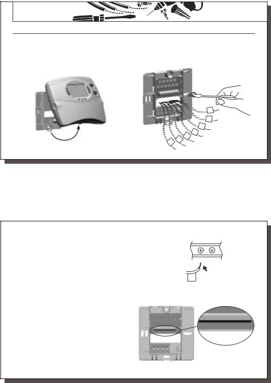
Mount Wallplate and Thermostat
■Remove the wallplate from your thermostat by pressing the release tab on the bottom of the thermostat. (See Figure 2.)
■Position wallplate on wall and pull existing wires through large opening. Then level for appearance. Mark holes for plastic anchors provided if your existing holes do not line up with those on the Hunter wallplate.
Figure 2
■Drill holes with 3/16" bit and gently tap anchors into the holes until flush with wall.
■Reposition wallplate to wall, pulling wires through large opening. Insert mounting screws provided into wall anchor and tighten. (See Figure 3.)
C
O
F
|
|
W2 |
G |
|
Y1 |
|
|
R |
|
|
|
|
|
|
Figure 3
15
Connect Wires and Mount Thermostat to Wallplate |
15 |
■Straighten bare end of each wire and cut or strip it to 1/4” maximum. Insert each labeled wire into the bottom of the maching terminal. Refer to figures 4 and 5.
■Hold the wires in each terminal and tighten the terminal screws securely, otherwise a loose wire could cause operational problems with your system or thermostat.
■Push excess wire back into hole to prevent interference with mounting of the thermostat.
■Make sure the Power Switch is set to OFF.
■Insert two AAA size alkaline batteries, observing the polarity marked on the unit.
■Insert the upper tabs on the thermostat body into the slot at the top of the wallplate. Press bottom of the thermostat body to snap it into the wallplate. (NOTE: Do not force the thermostat onto the wallplate, as the terminal pins may be damaged. If it does not snap properly, the thermostat may not work.)
■Switch on the main power at the panel or furnace.
R Y1
Figure 4
Insert
R
G C L O W2 B E R Y1
G C L O W2 B E R Y1
Figure 5

41652_model44760_web.pmd
16
PROGRAMMING |
16 |
|
Option Menu |
|
|
Your thermostat has many settings that can be adjusted to fit your system and preferences. |
|
|
option |
■ Press to enter the Option Menu and to change to the next option selection. |
|
ret-clear ■ Press at any time to return to normal mode.
Fahrenheit or Celsius (F°/C°) selection
option |
1 |
■ |
or |
to change the thermostat display between |
Temp |
|
|||||
|
|
Fahrenheit and Celsius. |
|
|
|
12 Hr or 24 Hr. Clock selection |
|
|
|
||
option |
2 |
■ |
or |
to change the time format display between |
Clock |
|
|||||
12 hour (AM / PM) and 24 hour (military).
17
Stage 1 SPAN selection |
|
Span Stg1 |
|
|
|
option 3 ■ |
or |
to change the SPAN setting to 1, 2, or 3. The |
factory setting is 2. Setting 1 will cause shorter cycle times. Setting 3 will cause longer cycle times.
Auto Recovery selection |
|
|
|
option 4 |
■ |
or |
to enable “YES” or disable “NO” the Auto |
|
|
Recovery Mode. The factory setting is “YES.” |
|
system ■ To change between Heat or Cool recovery modes.
Recovery
System
NOTE: Auto Recovery is one of the ENERGY STAR® features of this thermostat. Refer to the Auto Recovery section on pages 45-46 for more information.
LCD Contrast adjustment |
|
|
|
■ |
or |
to change the LCD contrast between 0 and 9. |
LCD |
option 5 |
Lower numbers lighten the display. Higher numbers darken the display. |
|
|
|
The factory setting is 5. |
|
|
 Loading...