


TRANSDUCER MOUNTING PROCEDURE
Humminbird’s high-speed transducer is supplied with your LCR. This transducer has been designed to give good high speed readings on most all boat designs, including aluminum.
Please carefully consider the following before installing your transducer.
TRANSDUCER MOUNTING OPTIONS
A.Transom MountThe Humminbird high speed transducer allows the transducer element to be mounted below the bottom of the boat hull keeping the transducer out of turbulent water and insuring good high speed operation. The transducer will absorb the blow of any obstruction
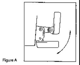
by rotating up out of the metal spring bracket without harming the transducer, or your boat. The transducer can be re-engaged by simply rotating the transducer down and snapping it back in place. (See Figure A)
B.Inside Hull MountThe high speed transducer can be mounted inside the hull (without pivot assembly) using the proper two-part epoxy, such as Humminbird’s epoxy kit. Even though there is some loss of signal in shooting through the hull, your LCR will perform well with this type of installation. You cannot shoot through the hull of an aluminum boat.
C.Trolling motor MountThis type of transducer is not supplied with your LCR. It is designed to mount on the foot of a trolling motor. You may exchange your un-used high speed transducer for a trolling motor transducer. Call the Humminbird Customer Service Department.
D.Bronz Thru-Hull MountThis transducer is not supplied with your LCR but for an additional cost you may exchange your un-used high speed transducer for a bronz thru-hull. The bronz thru-hull transducer has a threaded stem which installs through a hole drilled in the boat hull, leaving the housing exposed under the boat. This type of installation must be used for many boats with in-board engines, because there is no suitable location on the transom away from the noise and turbulence created by the prop. A bronz thru-hull transducer should be installed by qualified personnel only.
The LCR will operate well at high speeds with a properly mounted transducer. Remember, a transducer will not work transmitting through air or through air bubbles.
1.TRANSOM MOUNTING PROCEDURE
Step 1.
MOUNTING LOCATIONIt is important that the transducer be mounted on the transom where water flow is in constant contact with the transducer. You may wish to observe the rear of the boat while it is moving through the water to determine the best mounting location.
Step 2.
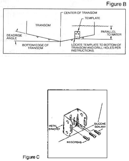
BRACKET INSTALLATION (Aluminum Boats)- To install the metal bracket on an aluminum boat locate the template on the transom between rows of rivets, or ribs that are on the bottom of the boat. Align the template so that the bottom corner of the template nearest the center of the transom is on the bottom edge of the transom.
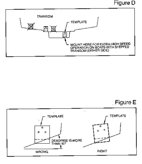
Once the location is determined mark and drill three 7/64” dia.. holes noted on the template. Attach the metal bracket using three #10 self threading screws supplied. Be sure to align holes in the center of the
Bracket slots. On some aluminum boats it may be necessary to use a wood back-up plate. It is important to use a silicone sealant between the screwhead and bracket in order to prevent leaking. (See Figure C)
Step 2.
BRACKET INSTALLATION (Fiberglass Boats)- If your boat has a stepped transom located below and under the main transom, the compact transducer design allows mounting in this area. This mounting location is recommended for good reading at very high speeds. (See Figure D)
To install the metal bracket on a fiberglass boat, locate the template on the transom in the same manner as for an aluminum boat. (See Figure C)
NOTE: On boats with more than 15 degree deadrise angle it may be necessary to mount the transducer slightly off parallel with the water level. (See Figure E)
Mark and drill the three 9/64” dia. holes as shown on the template. Attach the metal bracket using the three #10 self threading screws supplied. Be sure to align the holes so that they are centered vertically in the three slots found in the bracket. It is important to use a silicone sealant between the screwhead and bracket in order to prevent leaking.
Step 3.
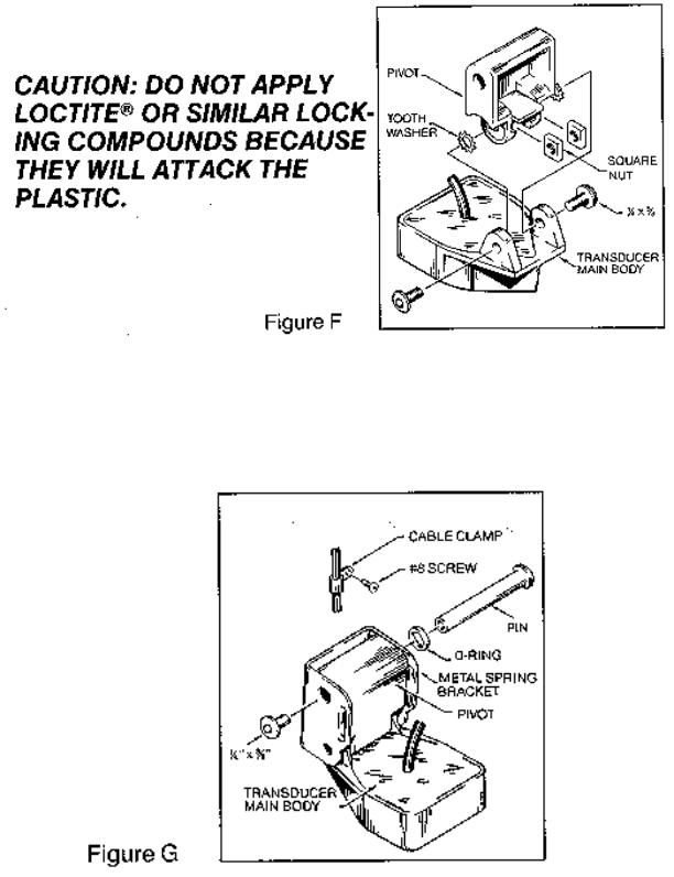
TRANSDUCER PIVOT ASSEMBLYAssemble the pivot to the transducer main body using the two ¼”x5/8” allen head screws, two 3/8” tooth washers and two, ¼” square nuts. Make sure the tooth washers are sandwiched between the transducer main body and the pivot. The square nuts are trapped inside the pivot and will not rotate as the allen head screws are tightened. HOWEVER, DO NOT TIGHTEN AT THIS POINT. (See Figure F)
Step 4
TRANSDUCER ASSEMBLYInsert the transducer assembly into the metal bracket from the bottom. Push up until the holes in the plastic pivot align with the uppermost holes in the bracket. Slide the O-ring on to the headed pin and insert it through the two parts. Assemble by screwing the ¼”x3/8” allen head screw into the end of the pin and tighten. (See Figure G)
Step 5
ANGLE ALLIGHMENTSet the transducer angle so that it is parallel with the bottom of the boat hull. Once proper alignment is achieved, tighten the two allen head screws using the 5/32” allen
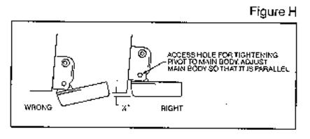
wrench provided. The screws are visible through the access holes on each side of the metal bracket. Check to make sure the transducer main body is rigidly fastened to the pivot. (See Figure H)
Step 6
CHECK POSITION OF TRANSDUCERAt this point, check to see that the bottom of the transducer is a minimum of ¼” below the bottom of the transom. (However, as noted in STEP 2, the top of the transducer cannot fall below the bottom of the transom). If it is not, remove the transducer assembly from the metal bracket by removing the pin installed during STEP 3. Loosen the metal bracket mounting screws, re-position the bracket utilizing it’s slotted holes, tighten and re-assemble. It may be necessary to replace the silicone sealant after this adjustment is made.
NOTE: It may be necessary to make several high speed runs to adjust transducer either UP/DOWN or to re-adjust the angle to achieve optimum results.
Step 7
CABLE CLAMPSInstall cable clamps as necessary by drilling a 1/8” dia. hole for the # 8 screw supplied.
2. INSIDE HULL MOUNTING PROCEDURE
Warning: In order to achieve proper results with this type installation, it is important that the transducer be mounted by someone familiar with the use of two part epoxy adhesives. For this reason, Techsonic Industries, Inc. will not be responsible for any damage due to the mounting of your transducer in this manner.
NOTE: An Epoxy Kit (Part N. EPK) is available from Humminbird. This Epoxy Kit has been formulated for Inside Hull Transducer Installation.
1.Select as flat an area as possible near the aft end and center of boat where the hull is thin and not double. If the bottom has a runner down the center of boat, select an area to one side of the runner, but as close to the runner as possible.
2.Clean the inside of the boat with lacquer thinner in the area transducer is to be mounted. Outside of boat in this area should also be cleaned. (Not with lacquer thinner).
3.Put approximately one inch of water in the bottom of the boat.
4.Put transducer in the water. The bottom of the transducer should be in a flat area and should be in good contact with the bottom of the boat.
5.Operate the LCR with the boat operating at high speed. The transducer may have to be moved in order to find an area where satisfactory operation is observed.
6.When an area is found that produces satisfactory operation, mark the location of the transducer.
 Loading...