

Hughes NH9000 Installation Manual

HN9000 Satellite Modem
Installation Guide
1037576-0001
Revision G
February 26, 2010

Copyright © 2008-2010 Hughes Network Systems, LLC
All rights reserved. This publication and its contents are propr ietary to Hughes Network Systems, LLC.
No part of this publication may be reproduced in any form or by any means without the written
permission of Hughes Network Systems, LLC, 11717 Exploration Lane, Germantown, Maryland 20876.
Hughes Network Systems, LLC has made every effort to ensure the correctness and complet
the material in th
herein. The information in this document is subject to change without notice. Hughes Network Systems,
LLC makes no warranty of any kind with regard to this material, including, but not limited to, the implied
warranties of merchantability and fitness for a particular purpose.
Hughes, Hughes Network Systems, HughesNet, and SPACEWAY are trademarks of Hughes Network
Systems, LLC. All other trademarks are the property of their respective owners. This product is
compatible with the Hughes SPACEWAY system.
is document. Hughes Network Systems, LLC shall not be liable for errors contained
eness of
Trademarks

Contents
Understanding safety alert messages.................................................................................xi
Scope and audience............................................................................................................xiii
Chapter 1: Satellite modem overview...........................................................1
Chapter 2: Preparing for installation.............................................................5
Messages concerning personal injury.....................................................................................................xi
Messages concerning property damage...................................................................................................xi
Safety symbols........................................................................................................................................xi
Supported congurations.........................................................................................................................2
Satellite modem specications.................................................................................................................4
Installation summary................................................................................................................................6
Installation checklist.................................................................................................................................8
Conducting a site survey..........................................................................................................................9
Instructions for other terminal components..............................................................................................9
Power supply information......................................................................................................................10
Primary tools and equipment needed for installation.............................................................................11
Additional equipment ............................................................................................................................11
Use a surge protector..................................................................................................................11
Requirements for IFL cables, connectors, and ground blocks...................................................12
A hub may be required...............................................................................................................12
Computer requirements..........................................................................................................................12
Chapter 3: Installing the satellite modem....................................................13
Operating environment...........................................................................................................................14
Ventilation and heat sources.......................................................................................................14
Modem operating position.....................................................................................................................14
Powering up the modem.........................................................................................................................15
Connecting the installer laptop to the modem........................................................................................16
Entering the installation parameters.......................................................................................................16
Chapter 4: Installing outdoor equipment and antenna pointing...............23
Installing the IFL cables.........................................................................................................................24
Routing and connecting the IFL cables......................................................................................24
IFL grounding requirement............................................................................................24
Labeling the IFL cables..................................................................................................25
Connecting the IFL cables to the modem.......................................................................25
Pointing the antenna...............................................................................................................................26
HN9000 Satellite Modem Installation Guide
1037576-0001 Revision G
iii

Contents
Chapter 5: Commissioning the satellite modem.........................................27
Prerequisites for commissioning............................................................................................................28
Monitoring the commissioning process ................................................................................................28
Commissioning and installation reference information.............................................................30
Commissioning activities and progress messages..........................................................30
Registration error messages............................................................................................32
Terminal Info parameters...............................................................................................33
Troubleshooting installation problems...................................................................................................35
Chapter 6: Validating the installation..........................................................37
A quick look at the validation procedure...............................................................................................38
Prerequisites...........................................................................................................................................38
Accessing the OVT................................................................................................................................39
Chapter 7: Activating the HughesNet service.............................................45
Service activation prerequisites..............................................................................................................46
Connecting the satellite modem to the customer’s computer.................................................................46
Activation procedure..............................................................................................................................48
Chapter 8: Completing the installation........................................................55
Printing the System Information page....................................................................................................56
Creating a shortcut to the System Control Center..................................................................................56
Installation and activation complete.......................................................................................................56
Chapter 9: System Control Center...............................................................57
Accessing the System Control Center....................................................................................................58
Creating a shortcut to the System Control Center......................................................................58
System Control Center home page.........................................................................................................58
Text links....................................................................................................................................59
Common features on System Control Center screens............................................................................60
Button links................................................................................................................................61
System Status button......................................................................................................61
Links in the left panel.................................................................................................................62
Small icon on System Control Center screens—access Advanced Pages..................................62
Status and information screens...................................................................................................63
State codes on status and information screens...............................................................64
Red ag indicator...........................................................................................................64
System Status page.................................................................................................................................65
Typical values for System Status parameters.............................................................................65
Red ags on System Status page................................................................................................67
Reception Information page...................................................................................................................68
iv
HN9000 Satellite Modem Installation Guide
1037576-0001 Revision G

Contents
Typical values for Reception Information parameters...............................................................69
Red ags on Reception Information page..................................................................................70
Transmission Information page..............................................................................................................71
Typical values for Transmission Information parameters..........................................................72
Red ags on Transmission Information page.............................................................................72
Terminal Status page..............................................................................................................................72
Typical values for Terminal Status parameters..........................................................................73
System Information page........................................................................................................................74
Typical values for System Information parameters....................................................................75
State codes..............................................................................................................................................78
Viewing the state codes list........................................................................................................82
Connectivity Test page...........................................................................................................................83
Chapter 10: LEDs..........................................................................................85
Front panel LEDs...................................................................................................................................86
LAN port LEDs......................................................................................................................................87
Chapter 11: Troubleshooting........................................................................89
Rescue switch.........................................................................................................................................90
Troubleshooting common problems.......................................................................................................90
Cannot access the System Control Center..............................................................................................91
Testing connectivity to the satellite........................................................................................................91
Chapter 12: Advanced Pages........................................................................95
Accessing the Advanced Pages..............................................................................................................96
Expanding and collapsing menus...........................................................................................................97
Opening the Installation sub-menu.........................................................................................................97
Appendix A: Alternate address for installing the modem..........................99
Conguring the installer laptop IP address............................................................................................99
Conguring a link-local IP address on the installer laptop......................................................100
Conguring a second IP address on the installer laptop..........................................................101
Using the alternate installation address................................................................................................102
Appendix B: Standards compliance...........................................................103
Electromagnetic interference (EMI).....................................................................................................103
FCC Part 15..............................................................................................................................103
Canada Class B warning...........................................................................................................104
Operational and safety requirements for Canada.................................................................................104
Repairs in Canada.....................................................................................................................104
HN9000 Satellite Modem Installation Guide
1037576-0001 Revision G
v

Contents
Appendix C: Acronyms used in this guide................................................105
vi
HN9000 Satellite Modem Installation Guide
1037576-0001 Revision G

Table of Figures
Figure 1: HN9000 satellite modem..................................................................................................................................1
Figure 2: Single-host conguration..................................................................................................................................2
Figure 3: Multiple-host conguration in an Ethernet wired LAN...................................................................................3
Figure 4: Private network conguration..........................................................................................................................3
Figure 5: Satellite modem installation summary..............................................................................................................7
Figure 6: Power supply for the HN9000 satellite modem .............................................................................................10
Figure 7: HN9000 in vertical position............................................................................................................................14
Figure 8: Powering up the modem.................................................................................................................................15
Figure 9: Connecting the installer’s laptop computer to the modem.............................................................................16
Figure 10: System Control Center home page...............................................................................................................17
Figure 11: Icon for opening Advanced Pages................................................................................................................18
Figure 12: Installation Parameters screen......................................................................................................................18
Figure 13: Fields where latitude and longitude are entered...........................................................................................19
Figure 14: Example of a GPS receiver display..............................................................................................................20
Figure 15: State code displayed below latitude and longitude elds.............................................................................20
Figure 16: Terminal Pointing Info screen.......................................................................................................................21
Figure 17: In-line connection of the DAPT ...................................................................................................................24
Figure 18: Connecting the transmit and receive cables..................................................................................................25
Figure 19: Terminal Initialization Sequence in progress................................................................................................28
Figure 20: Terminal Initialization Sequence complete...................................................................................................30
Figure 21: Latest values compared to target values (partial screen)..............................................................................38
Figure 22: Validate link on System Control Center page...............................................................................................40
Figure 23: Installation Portal, installer login screen.......................................................................................................41
Figure 24: Installation Portal Welcome screen...............................................................................................................42
Figure 25: Data Collection screen..................................................................................................................................42
Figure 26: Site and installer ID information..................................................................................................................43
Figure 27: OVT screen comparing latest and target values...........................................................................................44
Figure 28: Terminal Initialization Sequence screen – top part.......................................................................................46
Figure 29: Activate link indicating modem is ready for service activation...................................................................47
Figure 30: Connecting Ethernet cable to customer’s computer or other device............................................................48
Figure 31: Activate link on the System Control Center home page...............................................................................49
Figure 32: Subscriber agreement....................................................................................................................................50
Figure 33: Subscriber agreement with SAN and PIN elds..........................................................................................50
Figure 34: Welcome screen............................................................................................................................................51
Figure 35: Downloading Software screen......................................................................................................................52
Figure 36: Computer veried screen..............................................................................................................................52
Figure 37: Congure Software (HughesNet Tools) screen............................................................................................53
Figure 38: Implement Public IP? screen........................................................................................................................53
Figure 39: Activation Complete screen..........................................................................................................................54
Figure 40: Icon for creating shortcut..............................................................................................................................58
Figure 41: System Control Center home page...............................................................................................................59
HN9000 Satellite Modem Installation Guide
1037576-0001 Revision G
vii

Table of Figures
Figure 42: Common features on System Control Center screens..................................................................................60
Figure 43: System Control Center button links..............................................................................................................61
Figure 44: Icon for accessing the Advanced Pages........................................................................................................63
Figure 45: Format of status and information screens.....................................................................................................63
Figure 46: Example of a state code................................................................................................................................64
Figure 47: Red ag problem indicator...........................................................................................................................64
Figure 48: System Status page.......................................................................................................................................65
Figure 49: Reception Information page..........................................................................................................................69
Figure 50: Transmission Information page....................................................................................................................71
Figure 51: Terminal Status page (top part).....................................................................................................................73
Figure 52: System Information page (top part)..............................................................................................................75
Figure 53: Examples of state codes................................................................................................................................79
Figure 54: Terminal Connectivity Test page..................................................................................................................83
Figure 55: Front panel LEDs on the HN9000 modem...................................................................................................86
Figure 56: LAN port LEDs............................................................................................................................................87
Figure 57: Problem Troubleshooting page.....................................................................................................................90
Figure 58: Satellite loopback connectivity test..............................................................................................................91
Figure 59: Terminal Connectivity Test page..................................................................................................................92
Figure 60: Connectivity Test results page......................................................................................................................92
Figure 61: Icon for accessing Advanced Pages..............................................................................................................96
Figure 62: Advanced Pages example showing the Advanced menu..............................................................................97
Figure 63: Internet Protocol Properties dialog.............................................................................................................101
Figure 64: Settings for link-local and second address on the laptop............................................................................102
viii
HN9000 Satellite Modem Installation Guide
1037576-0001 Revision G

Table of Tables
Table 1: Specications for the HN9000 satellite modem ................................................................................................4
Table 2: Related installation documents...........................................................................................................................9
Table 3: Power supply specications for the HN9000 satellite modem........................................................................10
Table 4: Commissioning progress messages..................................................................................................................31
Table 5: Reasons for registration errors and corrective actions.....................................................................................32
Table 6: Parameters in Terminal Info section (appears on two installation screens).....................................................33
Table 7: Guidelines for installation troubleshooting......................................................................................................35
Table 8: Button links on System Control Center screens...............................................................................................61
Table 9: System Status button colors.............................................................................................................................62
Table 10: System Status parameters – typical values and range....................................................................................66
Table 11: Red ags on System Status page....................................................................................................................67
Table 12: Reception Information parameters – typical values and range......................................................................69
Table 13: Red ags on Reception Information page......................................................................................................70
Table 14: Transmission Information parameters – typical values and range.................................................................72
Table 15: Terminal Status parameters – typical values and range..................................................................................74
Table 16: System Information parameters – typical values and range...........................................................................76
Table 17: State codes......................................................................................................................................................79
Table 18: Front panel LED indications..........................................................................................................................86
Table 19: HN9000 standards compliance.....................................................................................................................103
HN9000 Satellite Modem Installation Guide
1037576-0001 Revision G
ix


Understanding safety alert messages
Safety alert messages call attention to potential safety hazards and tell you how to avoid them.
These messages are identied by the signal words DANGER, WARNING, CAUTION, or
NOTICE, as illustrated below. To avoid possible property damage, personal injury, or in some
cases possible death, read and comply with all safety alert messages.
Messages concerning personal injury
The signal words DANGER, WARNING, and CAUTION indicate hazards that could result in
personal injury or in some cases death, as explained below. Each of these signal words indicates
the severity of the potential hazard.
DANGER indicates a potentially hazardous situation which, if not avoided, will result in death
or serious injury.
WARNING indicates a potentially hazardous situation which, if not avoided, could result in
death or serious injury.
CAUTION indicates a potentially hazardous situation which, if not avoided, could result in
minor or moderate injury.
Messages concerning property damage
NOTICE is used for messages concerning possible property damage, product damage or
malfunction, data loss, or other unwanted results—but not personal injury.
Safety symbols
The generic safety alert symbol calls attention to a potential personal injury hazard. It
appears next to the DANGER, WARNING, and CAUTION signal words as part of the signal
word label. Other symbols may appear next to DANGER, WARNING, or CAUTION to indicate
HN9000 Satellite Modem Installation Guide
1037576-0001 Revision G
xi

a specic type of hazard (for example, re or electric shock). If other hazard symbols are used
in this document they are identied in this section.
Additional symbols
This document uses this symbol to indicate a safety alert message that concerns a potential
electric shock hazard.
xii
HN9000 Satellite Modem Installation Guide
1037576-0001 Revision G

Scope and audience
This installation guide explains how to install, commission, activate, and troubleshoot the Hughes
HN9000 satellite modem. It also contains certain reference information concerning operation
of the satellite modem.
This guide is written primarily for professional installers. It may also be useful for:
• Trainers who train installers
• Call center operators who respond to customers’ calls
This guide is written for satellite modem installations in the United States and Canada.
HN9000 Satellite Modem Installation Guide
1037576-0001 Revision G
xiii


Chapter
1
Satellite modem overview
Topics:
• Supported configurations
• Satellite modem specifications
The HN9000 satellite modem connects to the Internet or an intranet by satellite
and provides Internet or intranet service to a single host, typically a computer,
or to multiple hosts on a LAN. A host may be a computer using Windows or
other supported operating system.
The modem is a self-hosted unit, meaning that it does not depend on a computer
to establish and maintain the Internet or intranet connection. However, the
modem must be connected to a properly aligned satellite antenna. The modem
has an Ethernet port so it can be connected to a computer or to an Ethernet LAN.
Figure 1: HN9000 satellite modem
Note: Acronyms used in this installation guide are identied in Acronyms
used in this guide on page 105.
HN9000 Satellite Modem Installation Guide
1037576-0001 Revision G
1

Supported configurations
This section shows examples of supported congurations using the HN9000 satellite modem.
The satellite modem may be used in a single-host conguration or multiple-host conguration.
In a single-host conguration, the satellite modem is directly connected to the host (a computer),
as shown in Figure 2: Single-host conguration on page 2. The Hughes Internet Gateway is
a Hughes-operated satellite station that provides a connection between the Internet and the
satellite. The gateway routes data to and from the Internet and to and from the satellite, which
in turn beams a signal down to the satellite modem to provide Internet connectivity.
Satellite modem overviewChapter 1
Figure 2: Single-host configuration
In a multiple-host conguration, the hosts on the LAN share satellite Internet or intranet
connectivity through an Ethernet hub, router, or wireless base station. The satellite modem is
connected to the hub, router, or wireless base station, as shown in Figure 3: Multiple-host
conguration in an Ethernet wired LAN on page 3.
Note: The customer must provide and congure hub, router, or wireless base station
equipment.
HN9000 Satellite Modem Installation Guide
2
1037576-0001 Revision G

Chapter 1Satellite modem overview
Figure 3: Multiple-host configuration in an Ethernet wired LAN
Figure 4: Private network conguration on page 3 shows a private network using two satellite
modems at two locations. The thick broken line shows how the network connects a PC at one
location and to a PC at a second location. This conguration requires two antennas—one at each
location. The Hughes Internet Gateway connection is optional and is based upon the network
design for the customer private network. Typically this type of conguration is used only in
enterprise (business) environments.
Figure 4: Private network configuration
HN9000 Satellite Modem Installation Guide
1037576-0001 Revision G
3

Satellite modem specifications
Table 1: Specifications for the HN9000 satellite modem
Satellite modem overviewChapter 1
1.6 lb (0.73 kg)Weight
2.4 inch (6.1 cm)Width
7.8 inch (19.8 cm)Height
9.0 inch (22.9 cm)Depth
Safe operating temperature range
Protocol support
Interface ports
Power supplies and power requirements
5 to 40º C (Above 5000 ft altitude, the maximum
temperature is reduced by 1º C per 1000 ft.)
5% to 95% non-condensingSafe operating humidity range
Up to 10,000 ftSafe altitude
ConvectionCooling method
TCP/IP (Transmission Control Protocol / Internet
Protocol) protocol suite
One Ethernet port supporting 10BaseT or 100BaseT
operation, RJ-45-switched
See Power supply information on page 10.
HN9000 Satellite Modem Installation Guide
4
1037576-0001 Revision G

Chapter
2
Preparing for installation
Topics:
• Installation summary
• Installation checklist
• Conducting a site survey
• Instructions for other terminal
components
• Power supply information
• Primary tools and equipment
needed for installation
• Additional equipment
• Computer requirements
This section describes preparations for installing the satellite modem and includes
information you should know before you begin. Review this information before
you install the satellite modem, antenna assembly, antenna mount, or IFL cables.
Refer also to Installation summary on page 6.
To install the satellite modem, you need the Installation Reference Sheet. This
form includes parameters you need to enter to install the modem (A code, B
code, C code, and U code, which are explained later). Print the Installation
Reference Sheet for your specic installation from the online HughesNet
Installation Portal.
Before you proceed, review the sections in this chapter, which are listed in the
left panel.
HN9000 Satellite Modem Installation Guide
1037576-0001 Revision G
5

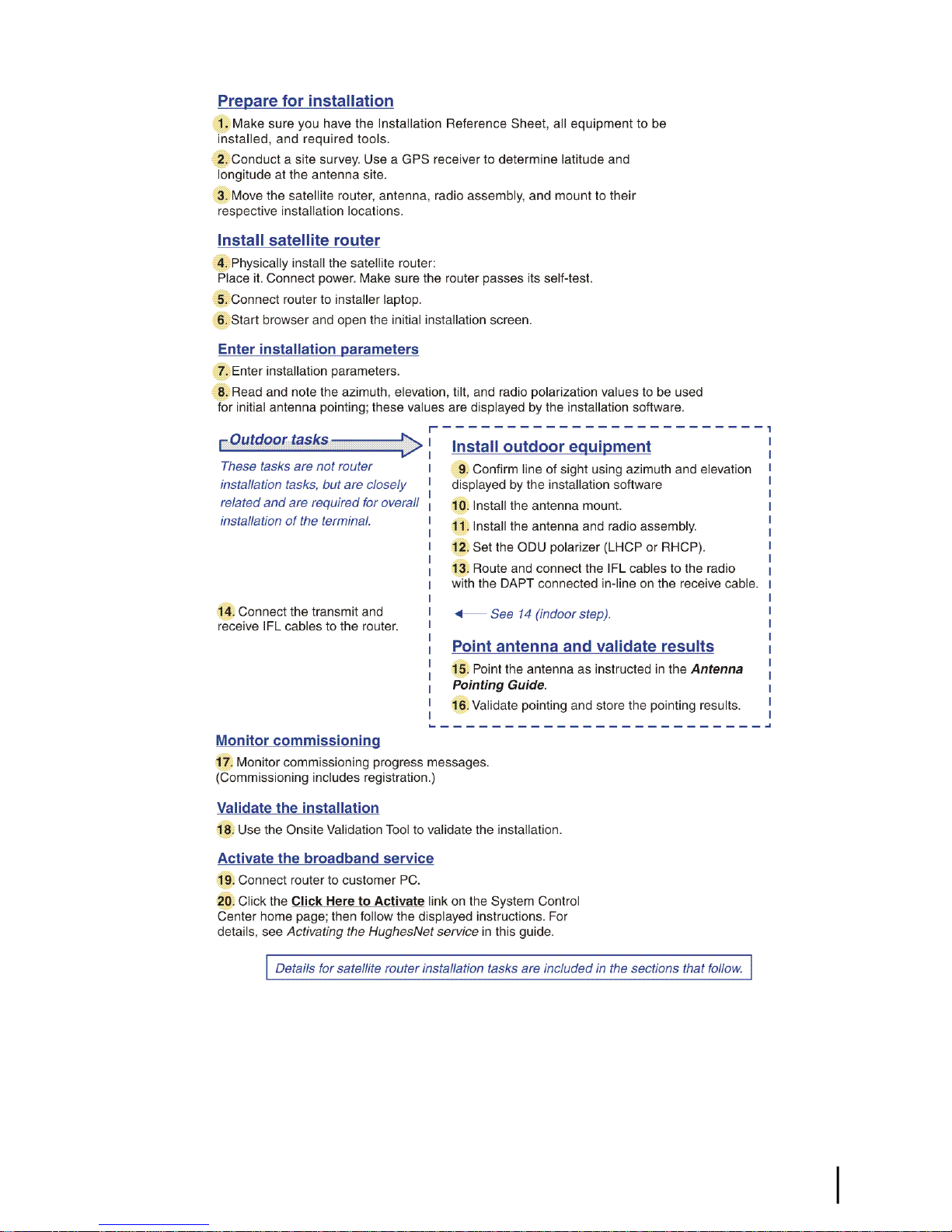
Installation summary
This installation guide covers installation of the satellite modem. It does not cover installation
of the other satellite terminal components: the antenna and radio assembly, antenna mount, and
IFL cables. However, to understand modem installation, you must understand the overall
installation process, which includes installation of all of the satellite terminal components. A
summary of the overall terminal installation process is presented in Figure 5: Satellite modem
installation summary on page 7. This diagram focuses on tasks performed by the installer to
install the satellite modem. Details for modem installation tasks are included in the sections that
follow.
Preparing for installationChapter 2
HN9000 Satellite Modem Installation Guide
6
1037576-0001 Revision G
Chapter 2Preparing for installation
Complete the steps in the order shown in Figure 5: Satellite modem installation summary on
page 7 unless you have a specic reason for doing them in a different order. In any case, make
sure all steps are completed. Be aware that the satellite modem has to provide the azimuth,
elevation, tilt angle, and ODU polarization values before antenna pointing can be completed.
Figure 5: Satellite modem installation summary
HN9000 Satellite Modem Installation Guide
1037576-0001 Revision G
7

Installation checklist
Later in the installation process you are instructed to use the onsite validation tool (OVT) to
validate the installation. Validation ensures that the site is performing to acceptable standards.
To increase the likelihood that the site will pass validation the rst time you try, pay careful
attention to the items listed in the checklist below as you install the modem, antenna, and
IFL cables.
IFL cables
For specic cable information see Table 2: Related installation documents on page 9.
cable part number.
Preparing for installationChapter 2
Use only Hughes-approved cables.
Do not exceed maximum length for the ODU type (such as 2 W or 4 W), cable type, and
Do not exceed the cable bend radius.
Properly terminate cables.
Connectors and connections
Use only connector types that are approved for the type of cable used. Check all connections
for tightness.
Outdoors:
Make sure F connectors connected to the radio assembly are tightened to 22 in-lb torque.
Carefully follow waterproong procedures, using dielectric grease and Hughes-approved
weatherproof tape.
Power source
Before connecting the modem power supply to the AC power source (using a surge protector),
use an AC outlet tester to verify that the power outlet is wired correctly. Wiring problems may
include:
• Hot and neutral wires reversed
• Neutral and ground wires reversed
• Open ground (incomplete connection)
• Open neutral
If the outlet is wired improperly, notify the customer that you are not permitted to connect the
system to a faulty outlet. Do not proceed with the installation until a properly wired outlet is
provided.
Grounding (modem, antenna, radio, and IFL)
Adhere to Hughes grounding requirements.
Use only approved ground wires, ground blocks, lugs, and clamps.
For detailed information refer to the appropriate FSB, as listed in Table 2: Related installation
documents on page 9.
HN9000 Satellite Modem Installation Guide
8
1037576-0001 Revision G
Conducting a site survey
Survey the customer site to conrm that it is satisfactory for installation of the satellite terminal.
The tasks listed here are the key tasks related to installation of the satellite modem. For complete
site survey information, see the Antenna Site Preparation and Mount Installation Guide
(1035678-0001).
1.
Use a GPS receiver to determine the latitude and longitude at the antenna site. Note the
readings.
2.
Make sure there is an unobstructed line of sight to the satellite indicated on the Installation
Reference Sheet.
3.
Conrm that the customer’s computer meets the requirements listed in Computer requirements
on page 12.
Instructions for other terminal components
Chapter 2Preparing for installation
This installation guide covers only installation of the satellite modem. For installation instructions
for other components, see Table 2: Related installation documents on page 9. You can view
or download these documents on the HughesNet Installation Portal at
https://dwayinstalls.hns.com/start/loginInstaller.jsp. If you have any problem logging in,
contact Hughes Installer Support.
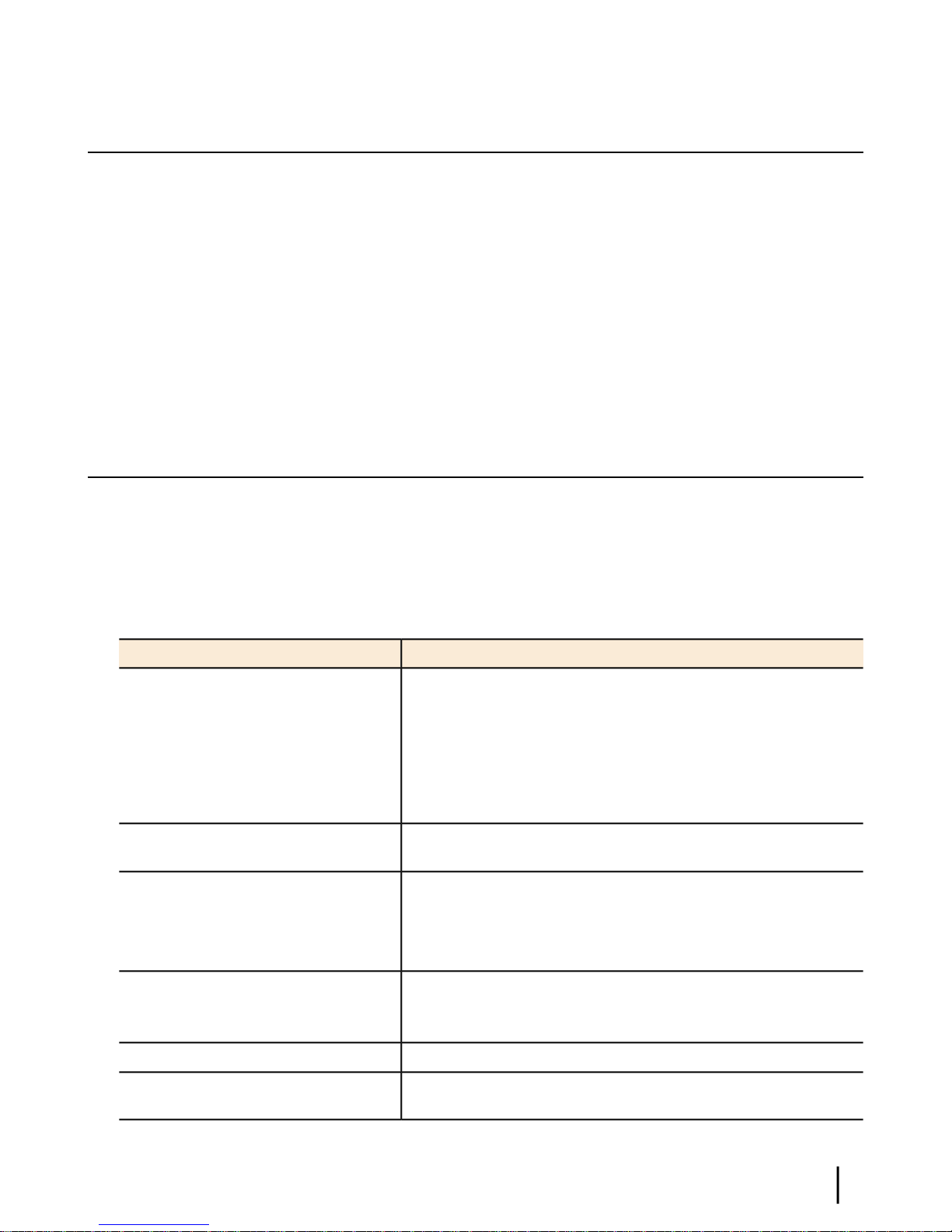
Table 2: Related installation documents
Safety (all components)
Site survey
Site preparation
Antenna mounts
IFL
IFL cables (specifications, approved
types, maximum lengths)
IFL cable connectors
Grounding
Ground blocks
Where to find instructionsComponent or topic
Antenna Site Preparation and Mount Installation Guide
(1035678-0001)
Field Service Bulletin (FSB), IFL Cable, Approved List (with
lengths) for Spaceway Domestic Installations (FSB_080202_01)
Field Service Bulletin (FSB), HNS Broadband Requirements for
RG-6 and RG-11 IFL Cable Connectors, Ground Blocks, and
Ground Block Location (FSB_050518_01)
Antenna
Radio assembly
Site validation (OVT)
See the antenna installation manual for the specific antenna model
you are installing.
Ka-Band Antenna Pointing Guide (1037663-0001)Antenna pointing
Installer’s Guide to the Ka-Band Onsite Validation Tool (OVT)
(1038091-0001)
HN9000 Satellite Modem Installation Guide
1037576-0001 Revision G
9
Also see and adhere to the customer-specic installation specication. Typically these
specications apply to all installations for a particular company.
Power supply information
The power supply is included in the satellite modem shipping carton.
Figure 6: Power supply for the HN9000 satellite modem
Preparing for installationChapter 2
Before proceeding, make sure you have the correct power supply. Check the part number on the
power supply and refer to Figure 6: Power supply for the HN9000 satellite modem on page 10.
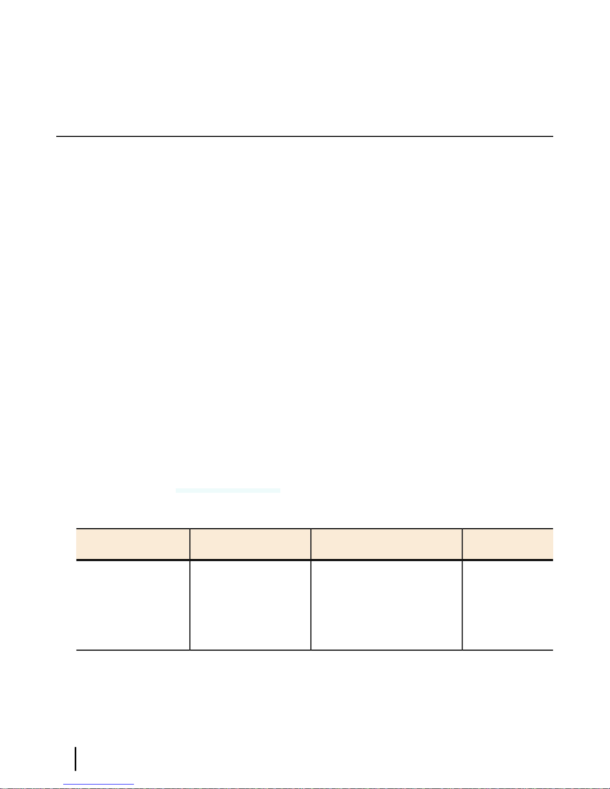
Table 3: Power supply specifications for the HN9000 satellite modem
Power supply type and
part number
AC/DC, 73 W
P/N 1501006-0001
• Always use the power supply provided with the satellite modem. The modem’s performance
may suffer if the wrong power supply is used.
• Connect the power supply to a three-wire, grounded outlet with an input of 110/130 VAC.
A suitable surge protector is recommended to protect the satellite modem from possible
damage due to power surges.
• If the satellite modem is installed outside the United States or Canada, observe the power
standards and requirements of the country where it is installed.
Power cordElectrical requirementsApplication
HN9000 satellite modem
with 1 W or 2 W radio
Input line voltage:
100 – 130 V, 2 A maximum
Input line frequency:
60 Hz AC
Detachable, for 110
VAC outlet type.
If there is any reason to remove power from the satellite modem, always unplug the AC power
cord from the power source (power outlet, power strip, or surge protector). Do not remove the
10
HN9000 Satellite Modem Installation Guide
1037576-0001 Revision G
Rated power consumption: 73 W

DC power cord from the modem’s rear panel. Doing so could result in an electrical shock or
damage the modem.
When you re-apply power to the modem, plug the AC power cord into the power source.
Primary tools and equipment needed for installation
To install the satellite modem, you need the following items, which are included in the satellite
modem shipping carton:
• Satellite modem.
• Power supply.
• Ethernet cable.
To install the satellite modem, antenna assembly, and IFL cables you also need the additional
items listed below.
• Antenna.
• IFL cables, cable connectors, and ground blocks – You need enough cable to connect the
satellite modem to the antenna (transmit cable and receive cable). For additional information,
see Table 2: Related installation documents on page 9.
• Laptop computer (installer computer) with Internet Explorer browser installed.
• DAPT – A small device that guides the installer through the antenna pointing process and
displays pointing values.
• Squinter – A tool used to ne point the antenna by capturing the satellite signal from different
portions of the antenna reector surface. The squinter type depends on the radio assembly
to be installed, as explained in the Ka-Band Antenna Pointing Guide (1037663-0001).
• GPS receiver – The GPS receiver must give readings accurate to 1/1000 minute (for example,
60 degrees, 15.152 minutes).
• Installation Reference Sheet – This document describes the work to be done and provides
important information that needs to be entered on the installation screens—the Terminal
site name or ID and parameters that are required for installation.
Chapter 2Preparing for installation
No tools are required to install the modem. For tools needed to install the antenna mount and
antenna and point the antenna, see:
• Antenna Site Preparation and Mount Installation Guide (1035678-0001)
• Ka-Band Antenna Pointing Guide (1037663-0001)
• The installation manual for the antenna model you are installing
Additional equipment
This section discusses additional equipment that is recommended and equipment you may need
depending on the specic installation.
Use a surge protector
The customer is advised to provide a surge protector (recommended). If a surge protector is not
present, connect the modem power supply to a wall outlet or other power source.
HN9000 Satellite Modem Installation Guide
1037576-0001 Revision G
11

A suitable surge protector is recommended to protect the satellite modem from possible damage
due to power surges.
Requirements for IFL cables, connectors, and ground blocks
You must use approved cable types and connectors to connect the modem to the outdoor satellite
antenna. For grounding, you must use approved ground blocks and grounding connectors. For
detailed specications and information on these components, see the documents listed in Table
2: Related installation documents on page 9.
A hub may be required
If the satellite modem is to be connected to a network, an Ethernet hub or other similar device
is required. The customer must supply and congure the hub or other device, including required
cables, according to the documentation for the hub or other network device.
Preparing for installationChapter 2
Computer requirements
The laptop computer you use to install the satellite modem and the customer’s computer that
will be connected to the modem should meet the minimum requirements specied by the computer
operating system manufacturer and the following networking and browser requirements.
Note: The satellite modem can be used with a Mac computer that meets these requirements,
but Mac computers are not supported as a tool for installing the satellite modem.
Networking requirements
• Ethernet port
• Ethernet cable (provided)
• Ethernet NIC, 10/100 Mbps, congured as follows:
• Auto-negotiate
• DHCP enabled (obtain an IP address automatically)
Internet browser
• Internet Explorer 6 or greater, Mozilla Firefox, Safari (for Windows and Mac)
• Browser settings:
Note: The computer can be congured to use a public IP address if the HughesNet
service plan provides for one or more public IP addresses. If the computer is congured
to use a specic public IP address, disable DHCP..
• HTTP 1.1 or greater enabled
• Proxy settings disabled
12
HN9000 Satellite Modem Installation Guide
1037576-0001 Revision G

Chapter
3
Installing the satellite modem
Topics:
• Operating environment
• Modem operating position
• Powering up the modem
• Connecting the installer laptop to
the modem
• Entering the installation
parameters
Installation of the HN9000 satellite modem consists of physical installation
followed by a highly automated process that fully prepares the modem for
operation on the satellite network. Installation tasks include:
• Physical installation and power-up
• Entering required installation parameters
• Pointing the antenna
• Monitoring the commissioning process
• Service activation
Typically, the satellite modem is installed as part of a new satellite terminal
installation. Under some circumstances, a modem may have to be re-installed.
Note: In some cases re-installation may correct a specic service problem.
Re-installation should only be done by a qualied installer or service
technician or someone under specic direction by Hughes Customer Care.
The installation software is factory pre-installed in the satellite modem. If
necessary, this software is automatically updated as part of the installation
process. You access the installation software through a browser on your installer
computer to perform tasks such as entering required installation parameters.
HN9000 Satellite Modem Installation Guide
1037576-0001 Revision G
13

Operating environment
Select a location for the satellite modem that will accommodate all required cable connections,
including connection to the power source.
Ventilation and heat sources
Make sure the installation location meets the following requirements concerning ventilation and
heat sources.
• Do not block any of the modem’s ventilation openings.
• Leave 6 inches of space around the top and sides of the modem to ensure adequate ventilation
and prevent overheating.
• Do not place the modem near a heat source such as direct sunlight, a radiator, heat register
or vent, oven, stove, amplier, or other apparatus that produces heat.
Installing the satellite modemChapter 3
Modem operating position
Install and operate the HN9000 modem only in a vertical position, that is, resting on its built-in
base as shown in Figure 7: HN9000 in vertical position on page 14.
Install and operate the HN9000 modem only in the upright vertical position as shown in Figure
7: HN9000 in vertical position on page 14. Any other position could result in insufcient
ventilation, overheating, and malfunction.
Figure 7: HN9000 in vertical position
14
HN9000 Satellite Modem Installation Guide
1037576-0001 Revision G

Powering up the modem
For this task you must have the satellite modem and the correct power supply. To make sure
you have the correct power supply, see Power supply information on page 10.
Test the power outlet and power up the satellite modem:
1.
Use an AC outlet tester to verify that the power outlet is wired correctly.
Wiring problems may include:
• Hot and neutral wires reversed
• Neutral and ground wires reversed
• Open ground (incomplete connection)
• Open neutral
If the outlet is wired improperly, notify the customer that you are not permitted to connect
the system to a faulty outlet. Do not proceed with the installation until a properly wired outlet
is provided.
2.
Connect the DC power cord to the modem’s DC IN connector, as shown in Figure 8: Powering
up the modem on page 15.
3.
Connect the AC power cord to the three-prong connector on the modem’s power supply.
4.
Connect the surge connector (recommended) to an AC power outlet.
5.
Apply power by connecting the AC power cord to the surge connector.
The Power LED turns on, and various LEDs turn on and off as the modem performs a self-test
and transitions to boot phase. (Indication that the self-test passed appears later as Self Test
: Passed on the screen shown in Figure 19: Terminal Initialization Sequence in progress
on page 28.)
Chapter 3Installing the satellite modem
A suitable surge protector is recommended to protect the satellite modem from possible
damage due to power surges.
Figure 8: Powering up the modem
HN9000 Satellite Modem Installation Guide
1037576-0001 Revision G
15

Connecting the installer laptop to the modem
For this task you need the provided Ethernet cable.
To access the satellite modem so you can perform the required installation procedures, you
connect your installer laptop computer to the modem. After the modem is installed and registered
with the satellite network, you connect the modem to the customer’s computer. During modem
installation the installer laptop computer must be directly connected to the modem without any
intervening connection.
Connect the installer laptop to the modem:
1.
Use the Ethernet cable to connect your laptop computer directly to the modem's LAN port,
as shown in Figure 9: Connecting the installer’s laptop computer to the modem on page 16.
Do not connect the installer laptop to the modem through an Ethernet router or switch.
Installing the satellite modemChapter 3
Figure 9: Connecting the installer’s laptop computer to the modem
2.
Make sure the satellite modem is not connected to the customer’s computer.
3.
If you are running rewall software on the laptop computer, disable it until you complete
installation of the modem.
The LAN LED on the front of the modem should now be on.
Entering the installation parameters
Prerequisites:
• Make sure DHCP is enabled on the installer laptop.
• Make sure you have the Installation Reference Sheet, which lists the parameters you need
to enter on the modem’s Installation Parameters screen.
Installation of the satellite modem is accomplished through actions performed by the installer,
network and installation software, and interaction between the satellite modem and the NOCC.
After powering up the modem, the installer enters required parameters. Then, before installation
can continue, the installer must accurately point the antenna.
16
HN9000 Satellite Modem Installation Guide
1037576-0001 Revision G
 Loading...