

Hughes HX90 User Manual

HX90 Satellite Router
User Guide
1039457-0001
Revisi on A
April 11, 2012
11717 Exploration Lane, Germantown, MD 20876
Phone (301) 428-5500 Fax (301) 428-1868/2830

Copyright © 2012 Hughes Network Systems, LLC
All rights reserved. This publication and its contents are proprietary to Hughes Network
Systems, LLC. No part of this publication may be reproduced in any form or by any means
without the written permission of Hughes Network Systems, LLC, 11717 Exploration Lane,
Germantown, Maryland 20876.
Hughes Network Systems, LLC has made every effort to ensure the correctness and
completeness of the material in this document. Hughes Network Systems, LLC shall not be
liable for errors contained herein. The information in this document is subject to change
without notice. Hughes Network Systems, LLC makes no warranty of any kind with regard to this
material, including, but not limited to, the implied warranties of merchantability and fitness for
a particular purpose.
Hughes, Hughes Network Systems, and HughesNet are trademarks of Hughes Network Systems,
LLC. All other trademarks are the property of their respective owners.
Trademarks

Contents
Understanding safety alert messages. . . . . . . . . . . . . . . .7
Messages concerning personal injury . . . . . . . . . . . . . . . . . . . . . . 7
Messages concerning property damage . . . . . . . . . . . . . . . . . . . . 7
Safety symbols. . . . . . . . . . . . . . . . . . . . . . . . . . . . . . . . . . . . . . . . . 8
Additional symbols . . . . . . . . . . . . . . . . . . . . . . . . . . . . . . . . . . . 8
Contact information. . . . . . . . . . . . . . . . . . . . . . . . . . . . . .9
Chapter 1
Satellite router overview. . . . . . . . . . . . . . . . . . . . . . . . .11
Scope of this user guide . . . . . . . . . . . . . . . . . . . . . . . . . . . . . . . . 12
The satellite router’s role . . . . . . . . . . . . . . . . . . . . . . . . . . . . . . . 12
Satellite router specifications . . . . . . . . . . . . . . . . . . . . . . . . . . . 14
LAN port configuration . . . . . . . . . . . . . . . . . . . . . . . . . . . . . . . . . 14
Router operating position . . . . . . . . . . . . . . . . . . . . . . . . . . . . . 15
Computer and networking requirements . . . . . . . . . . . . . . . . . . 16
Computer requirements. . . . . . . . . . . . . . . . . . . . . . . . . . . . . . 16
Networking and Internet browser requirements. . . . . . . . . . 16
Care of your satellite router. . . . . . . . . . . . . . . . . . . . . . . . . . . . . 16
Chapter 2
System Control Center. . . . . . . . . . . . . . . . . . . . . . . . . . .17
Accessing the System Control Center . . . . . . . . . . . . . . . . . . . . . 17
Creating a shortcut to the System Control Center . . . . . . . . . 17
System Control Center home page . . . . . . . . . . . . . . . . . . . . . . . 18
Text links . . . . . . . . . . . . . . . . . . . . . . . . . . . . . . . . . . . . . . . . . . 19
Common features on System Control Center screens . . . . . . . . 20
Button links . . . . . . . . . . . . . . . . . . . . . . . . . . . . . . . . . . . . . . . . 21
System Status button . . . . . . . . . . . . . . . . . . . . . . . . . . . . . . . . 22
IPSec icon. . . . . . . . . . . . . . . . . . . . . . . . . . . . . . . . . . . . . . . . . . 23
Links in the left panel . . . . . . . . . . . . . . . . . . . . . . . . . . . . . . . . 23
Small icon on System Control Center screens . . . . . . . . . . . 24
Status and information screens . . . . . . . . . . . . . . . . . . . . . . . . 24
Red flag indicator . . . . . . . . . . . . . . . . . . . . . . . . . . . . . . . . . . . 25
Features you may not see . . . . . . . . . . . . . . . . . . . . . . . . . . . . . . 26
System Status page . . . . . . . . . . . . . . . . . . . . . . . . . . . . . . . . . . . . 26
Reception Information page . . . . . . . . . . . . . . . . . . . . . . . . . . . . 28
Examining receive status . . . . . . . . . . . . . . . . . . . . . . . . . . . . . 29
Transmission Information page . . . . . . . . . . . . . . . . . . . . . . . . . . 30
Examining transmit status . . . . . . . . . . . . . . . . . . . . . . . . . . . . 30
• Contents
1039457-0001 Revision A
3

System Information page . . . . . . . . . . . . . . . . . . . . . . . . . . . . . . . 32
Port Forwarding Configuration page . . . . . . . . . . . . . . . . . . . . . . 33
Defining port forwarding rules . . . . . . . . . . . . . . . . . . . . . . . . 34
Checking download allowance status . . . . . . . . . . . . . . . . . . . . . 34
Help page. . . . . . . . . . . . . . . . . . . . . . . . . . . . . . . . . . . . . . . . . . . . 35
System Control Center tools for troubleshooting . . . . . . . . . . . 36
Chapter 3
LEDs . . . . . . . . . . . . . . . . . . . . . . . . . . . . . . . . . . . . . . . . . 37
Front panel LEDs . . . . . . . . . . . . . . . . . . . . . . . . . . . . . . . . . . . . . . 37
LAN port LEDs . . . . . . . . . . . . . . . . . . . . . . . . . . . . . . . . . . . . . . . . 39
Using LEDs for troubleshooting . . . . . . . . . . . . . . . . . . . . . . . . . . 39
Chapter 4
Troubleshooting . . . . . . . . . . . . . . . . . . . . . . . . . . . . . . . .41
Important troubleshooting information . . . . . . . . . . . . . . . . . . . 41
Troubleshooting reference diagram . . . . . . . . . . . . . . . . . . . . . . 42
Cannot access the Internet . . . . . . . . . . . . . . . . . . . . . . . . . . . . . 43
Confirming that the satellite router is commissioned . . . . . . 43
Confirming the receive signal . . . . . . . . . . . . . . . . . . . . . . . . . 44
Confirming the transmit signal . . . . . . . . . . . . . . . . . . . . . . . . 45
Confirming that TCP Acceleration is operational . . . . . . . . . . 45
Confirming that Web Acceleration is operational . . . . . . . . . 47
Confirming NOC connectivity. . . . . . . . . . . . . . . . . . . . . . . . . . 48
Confirming NOC connectivity (Static IP Address) . . . . . . . . . . 49
Confirming Internet connectivity. . . . . . . . . . . . . . . . . . . . . . . 51
Checking the DNS setting . . . . . . . . . . . . . . . . . . . . . . . . . . . . . 51
Checking for viruses and firewall issues . . . . . . . . . . . . . . . . . 51
Cannot access the System Control Center . . . . . . . . . . . . . . . . . 52
Satellite router connected directly to a computer. . . . . . . . . 52
Satellite router connected to an Ethernet device . . . . . . . . . 52
Using the front panel LEDs for troubleshooting . . . . . . . . . . . . . 53
Power LED off and one or more LEDs flashing . . . . . . . . . . . . 53
All LEDs flashing . . . . . . . . . . . . . . . . . . . . . . . . . . . . . . . . . . . . 54
All LEDs off. . . . . . . . . . . . . . . . . . . . . . . . . . . . . . . . . . . . . . . . . 54
Checking the Power LED. . . . . . . . . . . . . . . . . . . . . . . . . . . . . . 55
Checking the LAN LED. . . . . . . . . . . . . . . . . . . . . . . . . . . . . . . . 55
Problem with a connected device . . . . . . . . . . . . . . . . . . . . . . . . 56
Transmit LED is off . . . . . . . . . . . . . . . . . . . . . . . . . . . . . . . . . . 56
Receive LED is off . . . . . . . . . . . . . . . . . . . . . . . . . . . . . . . . . . . 57
System LED is off . . . . . . . . . . . . . . . . . . . . . . . . . . . . . . . . . . . . 57
Using the LAN port LEDs for troubleshooting. . . . . . . . . . . . . . . 58
Orange LED and the front panel LAN LED are both off . . . . . 58
Orange LED is on but the front panel LAN LED is not . . . . . . 58
Troubleshooting other problems. . . . . . . . . . . . . . . . . . . . . . . . . 59
• Contents
4
1039457-0001 Revision A

Hot cable connector . . . . . . . . . . . . . . . . . . . . . . . . . . . . . . . . . 59
Slow speed or intermittent operation. . . . . . . . . . . . . . . . . . . 60
Viewing problem-related statistics . . . . . . . . . . . . . . . . . . . . . . . 60
Weather and signal strength . . . . . . . . . . . . . . . . . . . . . . . . . . . . 61
Checking the power supply . . . . . . . . . . . . . . . . . . . . . . . . . . . . . 62
Appendix A
Computer settings . . . . . . . . . . . . . . . . . . . . . . . . . . . . . .63
Understanding the router address and computer address . . . . 63
Configuring a computer to use DHCP . . . . . . . . . . . . . . . . . . . . . 64
How do I know if DHCP should be enabled?. . . . . . . . . . . . . . 64
Configuring Windows 7 to use DHCP . . . . . . . . . . . . . . . . . . . 65
Configuring Windows Vista to use DHCP . . . . . . . . . . . . . . . . 66
Configuring Windows XP to use DHCP . . . . . . . . . . . . . . . . . . 68
Configuring a Mac computer to use DHCP . . . . . . . . . . . . . . . 70
Configuring a computer to use a static IP address . . . . . . . . . . . 71
Configuring Windows 7 to use a static IP address . . . . . . . . . 72
Configuring Windows Vista to use a static IP address . . . . . . 74
Configuring Windows XP to use a static IP address . . . . . . . . 76
Configuring a Mac computer to use a static IP address. . . . . 78
Configuring proxy settings . . . . . . . . . . . . . . . . . . . . . . . . . . . . . . 79
Appendix B
Standards compliance . . . . . . . . . . . . . . . . . . . . . . . . . . .81
Safety - Operating conditions for Canada . . . . . . . . . . . . . . . . . . 81
Repairs in Canada . . . . . . . . . . . . . . . . . . . . . . . . . . . . . . . . . . . 81
Electromagnetic interference (EMI) . . . . . . . . . . . . . . . . . . . . . . 82
FCC Part 15 . . . . . . . . . . . . . . . . . . . . . . . . . . . . . . . . . . . . . . . . 82
Canada Class B warning . . . . . . . . . . . . . . . . . . . . . . . . . . . . . . 83
R&TTE (EU) . . . . . . . . . . . . . . . . . . . . . . . . . . . . . . . . . . . . . . . . 83
Electromagnetic compatibility (EMC) . . . . . . . . . . . . . . . . . . . . . 83
R&TTE (EU) . . . . . . . . . . . . . . . . . . . . . . . . . . . . . . . . . . . . . . . . 83
IPoS. . . . . . . . . . . . . . . . . . . . . . . . . . . . . . . . . . . . . . . . . . . . . . . . . 83
Acronyms and abbreviations . . . . . . . . . . . . . . . . . . . . . .85
Index. . . . . . . . . . . . . . . . . . . . . . . . . . . . . . . . . . . . . . . . .87
• Contents
1039457-0001 Revision A
5

• Contents
6
1039457-0001 Revision A
Understanding safety alert messages
DANGER
WARNING
CAUTION
NOTICE
Safety alert messages call attention to potential safety hazards and tell you how to
avoid them. These messages are identified by the signal words DANGER, WARNING,
CAUTION, or NOTICE, as illustrated below. To avoid possible property damage,
personal injury, or in some cases possible death, read and comply with all safety alert
messages.
Messages concerning personal injury
The signal words DANGER, WARNING, and CAUTION indicate hazards that could
result in personal injury or in some cases death, as explained below. Each of these
signal words indicates the severity of the potential hazard.
DANGER indicates a potentially hazardous situation which, if not avoided, will
result in death or serious injury.
WARNING indicates a potentially hazardous situation which, if not avoided,
could result in death or serious injury.
CAUTION indicates a potentially hazardous situation which, if not avoided, could
result in minor or moderate injury.
Messages concerning property damage
A NOTICE concerns property damage only.
NOTICE is used for advisory messages concerning possible property damage,
product damage or malfunction, data loss, or other unwanted results—but not
personal injury.
• Understanding safety alert messages
1039457-0001 Revision A
7

Safety symbols
Additional symbols
The generic safety alert symbol calls attention to a potential personal injury hazard. It
appears next to the DANGER, WARNING, and CAUTION signal words as part of the
signal word label. Other symbols may appear next to DANGER, WARNING, or
CAUTION to indicate a specific type of hazard (for example, fire or electric shock). If
other hazard symbols are used in this document they are identified in this section.
This document also uses the following hazard symbols:
Indicates a safety message that concerns a potential
electric shock hazard.
Indicates a safety alert message that concerns a
potentially hazardous situation in which you could be
exposed to radio frequency (RF) energy.
• Understanding safety alert messages
8
1039457-0001 Revision A

Contact information
If you experience a problem with your HX90 satellite router, first try the solutions
offered in
contact information listed here.
If you need operational, warranty, or repair support, who you should contact
depends on where you purchased your satellite router. You may be supported by
Hughes Customer Care or another service provider. Please contact your customer
service representative in accordance with your service agreement.
For satellite routers purchased from a retail channel or Hughes
sales agent in the United States or Canada
If you purchased this product through a retail channel or Hughes sales agent, you
have several support options. Please try these options in the order listed until you
find the help you need.
Begin at the HughesNet Customer Care page:
1. Open a web browser on a computer connected to the satellite router.
2. Enter the web address www.myhughesnet.com.
3. Click the HughesNet Customer Care link.
The HughesNet Customer Care page opens. Options 1, 2, and 3 below are available
on this page:
Chapter 4 – Troubleshooting on page 41. If you need assistance, use the
1. Search our Knowledge Base.
a. In the Self help section, click Knowledge Base Search.
b. Follow the on-screen instructions to find the information you need.
2. Email a Customer Care representative.
a. In the Contact Hughes section, click Email.
b. Complete the email form.
c. Click Email Us!
3. Chat with a Customer Care representative.
a. In the Contact Hughes section, click Chat.
b. Complete the chat form.
c. Click Chat with Us!
4. Call a Customer Care representative.
If none of these options helps you, call Hughes Customer Care at
1 (866) 347-3292.
For satellite routers purchased from a value-added reseller (VAR)
in the United States or Canada
If you purchased this product from one of our VARs, do not contact Hughes. Contact
your VAR for technical support according to the procedure supplied by them. They
are trained to help you with any technical problem.
• Contact information
1039457-0001 Revision A
9

10
• Contact information
1039457-0001 Revision A
Chapter 1
Satellite router overview
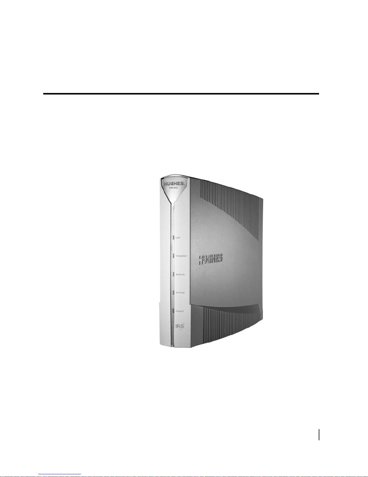
The HX90 satellite router connects to a satellite network to provide Internet or
intranet service or both to a host—typically a computer—or to multiple hosts on a
wired (Ethernet) or wireless local area network (LAN). The router has two Ethernet
LAN ports so it can be connected to one or two LAN subnets. The HX90 satellite
router is designed to meet the needs of enterprise business customers, small
business users, and consumers.
The HX90 is an Internet Protocol (IP) router, and so it eliminates the need for an
ternal router.
ex
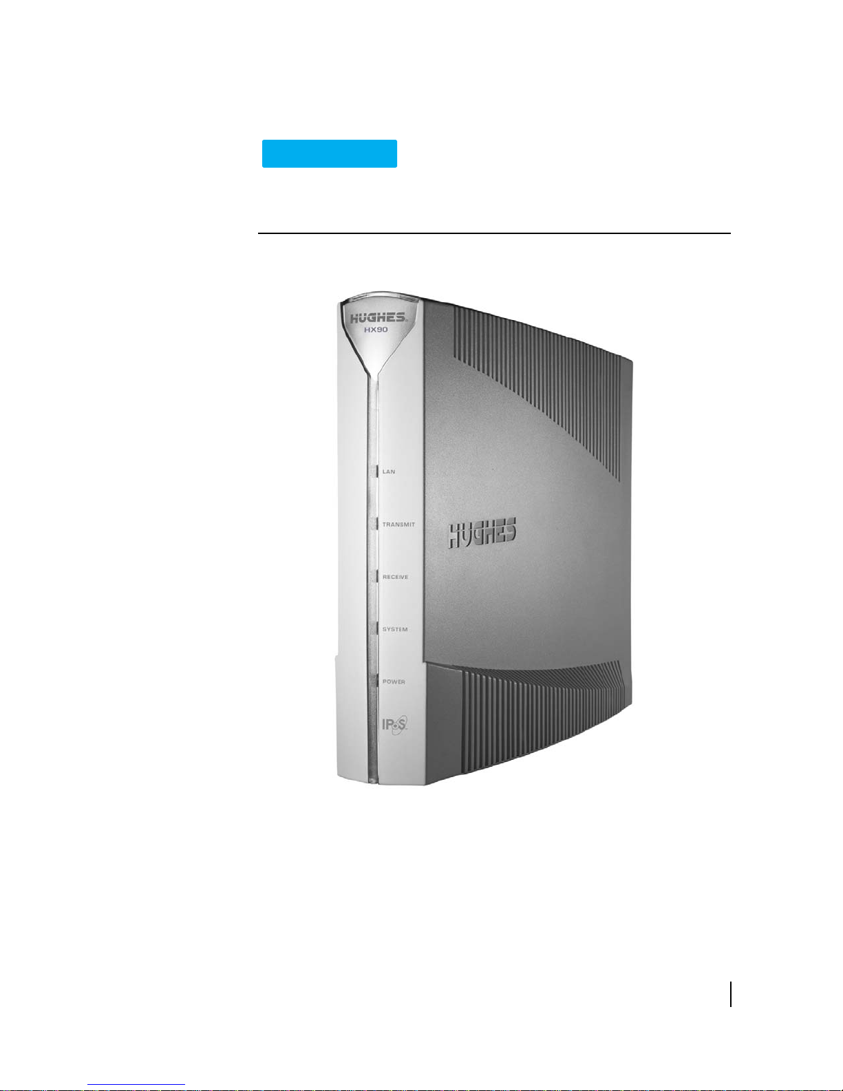
Figure 1: HX90 satellite router
Chapter 1 • Satellite router overview
1039457-0001 Revision A
11
After your HX90 satellite router has been installed, you can use a web browser on
- Mac
- UNIX
- PC
- Linux
Computer
workstation:
Antenna
Satellite
Satellite
router
Internet
d i g i t a l
TM
d i g i t a l
TM
VAXstation 3100
Hughes Internet
Gateway
your computer to access the Internet or an intranet. You can use a LAN to extend
Internet or intranet connectivity to multiple computers.
The satellite router has a System Control Center that provides access to system
ormation such as the router’s operating status and troubleshooting information.
inf
The System Control Center is described in Chapter 2 – Sy
page 17.
Terminology
In this user guide:
ellite router and router both refer to the HX90 satellite router.
• Sat
onyms are identified in Appendix C – Acronyms used in this guide, on page 89
• Acr
Scope of this user guide
This user guide describes the features and operation of the HX90 satellite router,
which provides you Internet access by satellite. This guide also provides certain
reference information, such as the meaning of the router’s front panel LEDs. The
HX90 satellite router is designed to meet the needs of enterprise business customers,
small business users, and consumers.
Audience
This guide is intended for users of the HX90 satellite router.
stem Control Center on
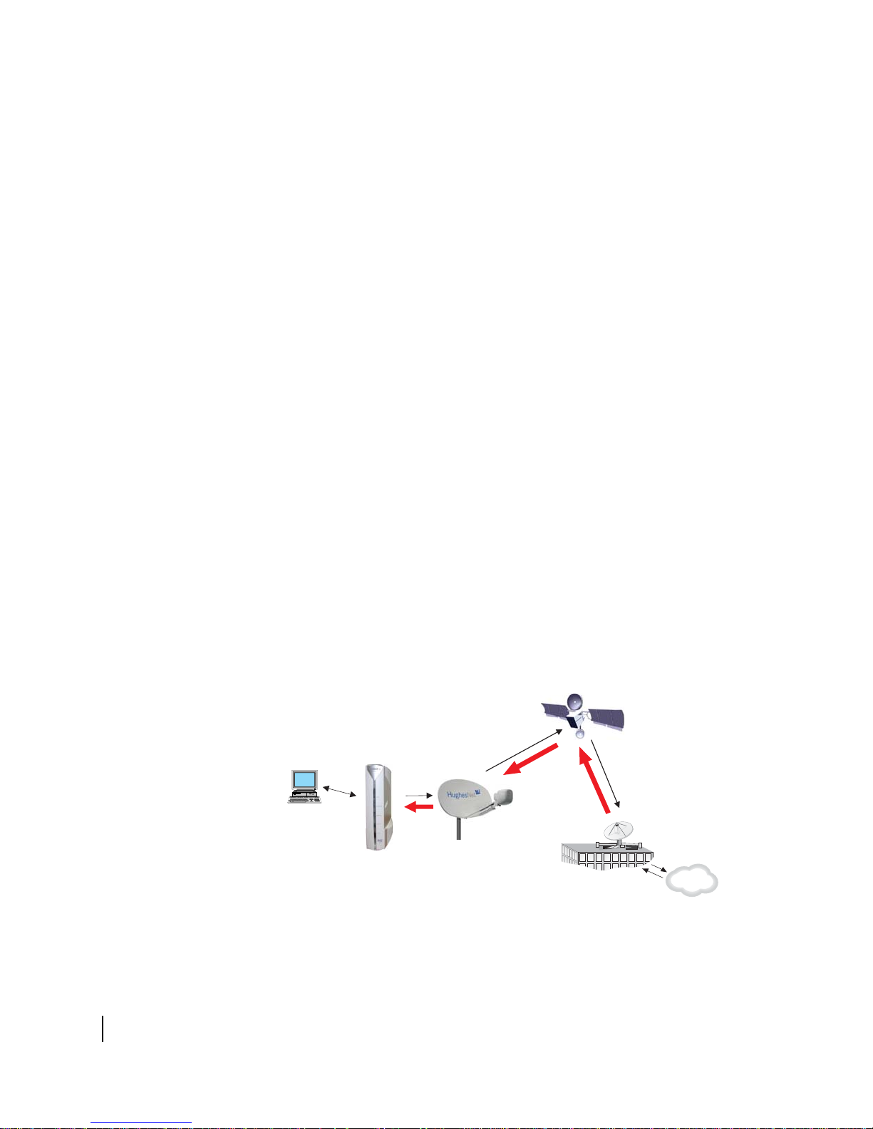
The satellite router’s role
Figure 2 illustrates how the HX90 satellite router provides connectivity and
functionality that allow a computer, Ethernet device, or LAN to connect to the
In
ternet by satellite.
Figure 2: Role of the HX90 in a satellite network
12
Chapter 1 • Satellite router overview
1039457-0001 Revision A
This illustration shows the HX90 with a single computer host. However, the satellite
CAUTION
router may also be used in a multiple-host configuration, in which hosts on a LAN
share satellite Internet or intranet connectivity through an Ethernet hub, router, or
wireless base station. A host may be a computer using Windows, Mac OS, or another
supported operating system.
Note: Y
Even though the HX90 satellite router is typically connected to a host, it is
self-hosted, meaning it can operate without a host. It does not depend on a
computer to establish and maintain the Internet or intranet connection. However,
the router must be connected to a satellite antenna.
The Hughes Internet Gateway is a Hughes-operated satellite station that provides a
c
from the Internet and to and from the satellite. The satellite transmits a signal to the
antenna, which is passed to the satellite router to provide Internet connectivity.
ou must provide and configure hub, router, or wireless base station
equipment if any of these are used.
onnection between the Internet and the satellite. The gateway routes data to and
This message applies if you use the HX90 satellite router in the United States: If
servicing of the satellite router’s outdoor antenna assembly is necessary, the
FCC requires that the work must be done by a trained professional because the
antenna assembly transmits RF energy.
Chapter 1 • Satellite router overview
1039457-0001 Revision A
13

Satellite router specifications
Table 1 : Specifications for the HX90 satellite router
Weight 1.6 lb (0.73 kg)
Height 8.0 inches (20.3 cm)
Width 1.6 inches (4.1 cm); 2.4 inches (6.1 cm) at base
Depth 9.0 inches (22.9 cm)
Operating temperature range
Operating humidity range 5% to 90% non-condensing
Altitude Up to 15,000 ft (4,572 m)
Cooling method Convection
Protocol support TCP/IP (Transmission Control Protocol/Internet Protocol)
Supported frequency ranges Ka-band or Ku-band
Network interface ports Two RJ-45 Ethernet LAN ports supporting 10BaseT or
Power supplies and power requirements See Checking the power supply on page 62.
32° F to 122° F (0° C to 50° C)
Above 5,000 ft (1,524 m) altitude, the maximum temperature
is reduced by 1
pr
otocol suite
00BaseT operation
1
° C per 1,000 ft (305 m).
LAN port configuration
The satellite router’s two LAN ports support the following configurations:
• Dual port, single subne
the NOC, which means the router supports one subnet. This is the default
configuration.
• Dual port, independen
address at the NOC, which means the router supports independent subnets.
t – Only one LAN port is configured with an IP address at
t subnet – Each LAN port is configured with a separate IP
14
Chapter 1 • Satellite router overview
1039457-0001 Revision A
Router operating position
NOTICE
Operate the HX90 router only in the upright vertical position as shown in
Figure 3. Any other position could result in insufficient ventilation, overheating,
and malfunction.
Figure 3: HX90 in vertical position
Chapter 1 • Satellite router overview
1039457-0001 Revision A
15

Computer and networking requirements
This section lists the requirements for the computer or other device, network, and
browser to be used with the satellite router.
Computer requirements
The HX90 satellite router can be used with any device that supports IP and has a
10/100 BaseT Ethernet LAN port. Typically, the router is connected to a customer’s
computer. However, the HX90 is self-hosted; it does not require a computer for any
of its functions.
The computer that connects to the satellite router should meet the minimum
requirements specified by the computer operating system manufacturer and the
following networking and browser requirements.
Networking and Internet browser requirements
• Ethernet port
• Ethernet network interface card (NIC) installed on at least one computer,
10/100 BaseT (10/100 Mbps)
• Ethernet cable (provided for consumer installations)
• A web browser such as Internet Explorer with proxy settings disabled
Connecting a network – If you want to connect a network to the satellite router, this
requires an Ethernet hub or other such device. You must supply and configure the
hub and cables.
Static IP address – The computer can be configured to use a static IP address if the
HughesNet service plan provides for one or more static IP addresses. If the computer
is configured to use a specific static IP address, disable DHCP. For additional
information see
Configuring a computer to use DHCP on page 64.
Care of your satellite router
• Leave the HX90 router powered on at all times. This allows automatic updates of
the router’s software whenever necessary.
• Leave 6 inches of space around the top and sides of the router to ensure
adequate ventilation.
• If you dust the router, use a soft cloth.
• If you clean the router, do not use solvent or abrasive powder.
16
Chapter 1 • Satellite router overview
1039457-0001 Revision A

System Control Center
The System Control Center is a set of screens and links you can use to monitor your
broadband service and troubleshoot the satellite router in the event of a problem.
The System Control Center provides access to system status, configuration
information, and online documentation through a web browser on a computer
connected to the satellite router. Use the System Control Center to find system
information for configuring networks or to check system performance if the satellite
router does not seem to be functioning properly.
Accessing the System Control Center
Prerequisites: To access the System Control Center, a computer with a web browser
installed must be connected to one of the satellite router’s LAN ports. (Because the
System Control Center web site is hosted on the router, the computer does not have
to be connected to the Internet.)
To open the System Control Center, double-click the System Control Center shortcut
on your computer desktop, or follow these steps:
1. Open a web browser such as Internet Explorer.
2. In the browser address bar, type www.systemcontrolcenter.com or
192.168.0.1 and press Enter.
Chapter 2
Note: To use 192.168.0.1, DHCP must be enabled on the computer.
The System Control Center home page appears as shown in Figure 5 on page 18.
If you are unable to access the System Control Center, refer to Cannot access the
System Control Center on page 52.
Creating a shortcut to the System Control Center
You can create a Windows shortcut on your computer desktop for easy access to the
System Control Center home page.
Note: You may already have a shortcut to the System Control Center on your desktop
if your satellite router installer created one.
1. Open the System Control Center home page in a web browser.
Chapter 2 • System Control Center
1039457-0001 Revision A
17
Note: The method described here works for Internet Explorer. For other
browsers see the browser’s instructions for creating a shortcut to a URL.
2. Drag the icon that appears in front of the address displayed in the browser to the
computer desktop.
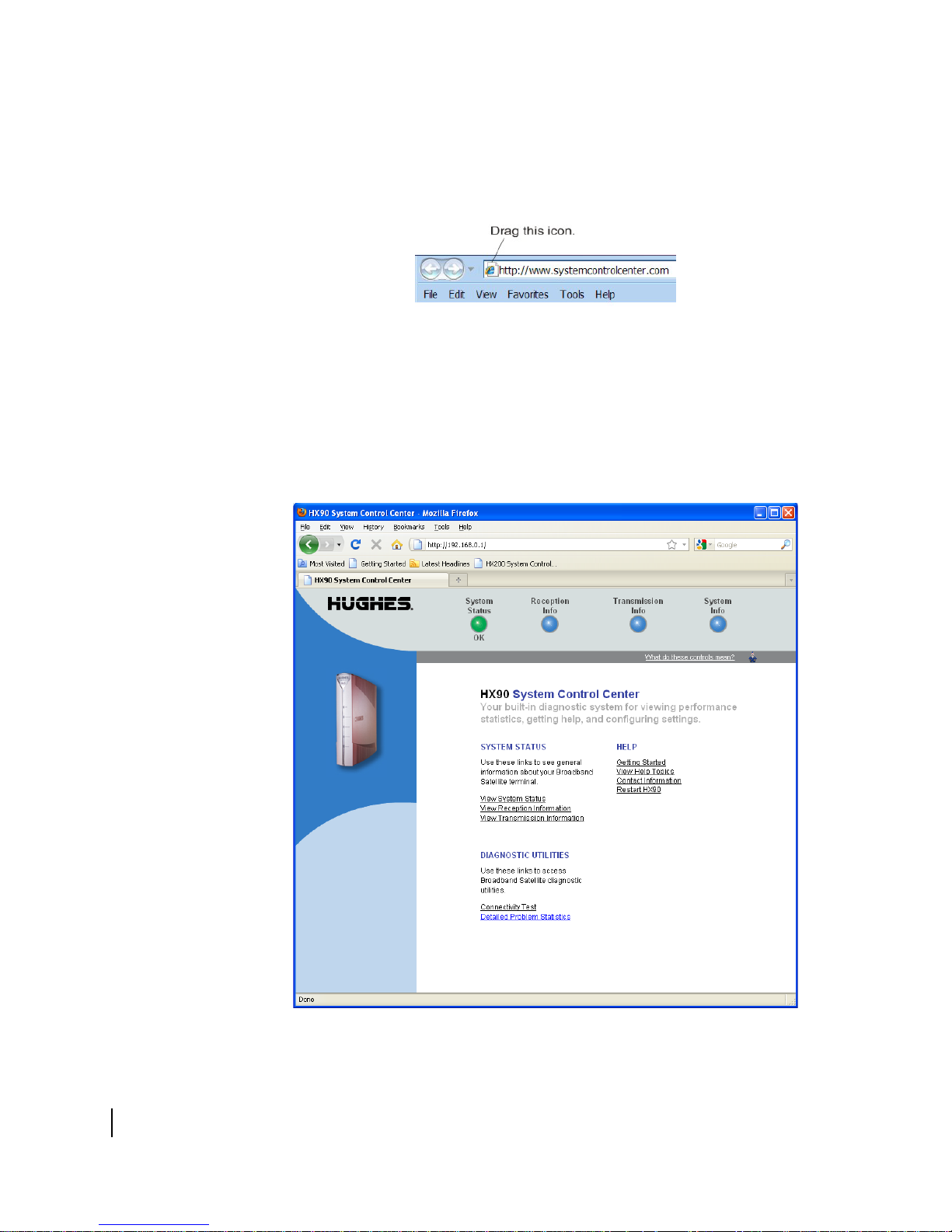
Figure 4: Icon used to create shortcut
System Control Center home page
The System Control Center home page contains numerous links to satellite router
features and important information regarding operation of the satellite router.
The button links at the top of the page appear on all System Control Center screens
and
are explained in Button links on p
age 21.
18
Chapter 2 • System Control Center
1039457-0001 Revision A
Figure 5: System Control Center home page

Text links
Note: The following apply to the screen illustrations in this user guide:
• Most screen illustrations show only the relevant part of the screen and do
not include features such as browser menus, toolbars, and window borders.
• The screen illustrations are examples. You may see screens with different
information. Do not apply information such as configuration values shown in
the illustrations unless the instructions say to do so.
• On some screens and in some messages you may see the word terminal or
the abbreviation VSAT. Both refer to the HX90 satellite router.
• Screen and page are both used to refer to a set of information from your
computer or satellite router that is displayed on your computer monitor.
The System Control Center home page includes the following text links:
System Status links
• View System Status – Opens the System Status page, which displays general
system status information such as signal strength and administrative status.
• View Reception Information – Opens the Reception Information page, which
displays information on data received by the satellite router.
• View Transmission Information – Opens the Transmission Information page,
which displays information on data transmitted by the satellite router.
Note: These links take you to the same destinations as the button links at the top of
each System Control Center page.
Diagnostic utilities links
Connectivity Test – Opens the Connectivity Test page, which you can use to test the
connection between the satellite router and the NOC. See
connectivity on page 48.
Detailed Problem Statistics – Opens a screen you can use to view statistics concerning
router operation. See
Viewing problem-related statistics on page 60.
Confirming NOC
Help links
Getting Started – Through this link you can find general operating instructions for the
HX90 router, recommended settings for your browser and TCP/IP, answers to
frequently asked questions, and troubleshooting information.
Browsing Optimization Utility – The Browser Optimization Utility is a software utility
you can download that configures certain settings on your Windows computer to
improve your Internet browsing performance. (This link is only present if it has been
enabled by the NOC.)
View Help Topics – Opens the Help page, which includes a variety of topics such as
recommended browser and TCP/IP settings.
Contact Information – Opens to a page that provides contact information for
assistance and additional information.
Chapter 2 • System Control Center
1039457-0001 Revision A
19
Restart HX90 – Restarts the satellite router.
myHughesNet
Note: myHughesNet links may or may not be present on your satellite router
depending on the country where the router is used and your service plan.
Go to myHughesNet provides access to the HughesNet Web Portal, which contains a
variety of useful tools, resources, and information. Access to the HughesNet portal is
determined by your specific service plan or your organization’s service plan.
From the HughesNet portal you can click the
a wide variety of support resources. For example, you can check online usage, test
satellite speed, find troubleshooting scripts, manage passwords, access email, check
your account and service plan information, and more. The specific portal information
and available features are determined by your specific service plan or your
organization’s service plan.
HughesNet Customer Care link to access
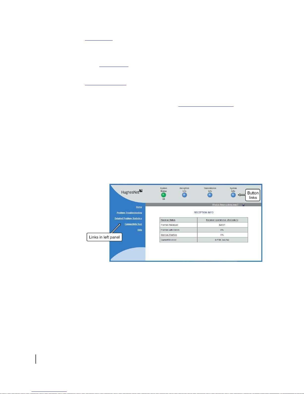
Common features on System Control Center screens
Certain features are common to some or all of the System Control Center screens, as
shown in Figure 6. These features are explained in the following sections.
20
Chapter 2 • System Control Center
1039457-0001 Revision A
Figure 6: Common features on the System Control Center screens
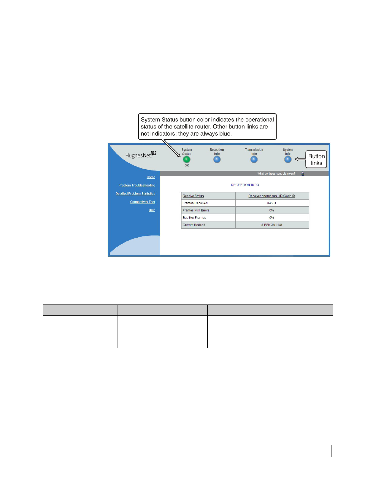
Button links
At the top of each System Control Center page are four round buttons with labels
above them as shown in Figure 7 on page 21. Each button is a link to the System
Control Center page identified by the label—for example, the S
a link to the System Status page. Click the button to go to the page identified by the
label. The System Status button link is also a status indicator, as explained in Table 3
on page 22. The other three button links are links only; they are not indicators.
ystem Status button is
Figure 7: System Control Center button links
The destination page for each button link is identified below:
Table 2: Button links on System Control Center screens
Button Destination Description of destination page
System Status System Status page Displays general status information such as
signal strength and commissioning status. For
more information see System Status page
page 26
.
on
Chapter 2 • System Control Center
1039457-0001 Revision A
21
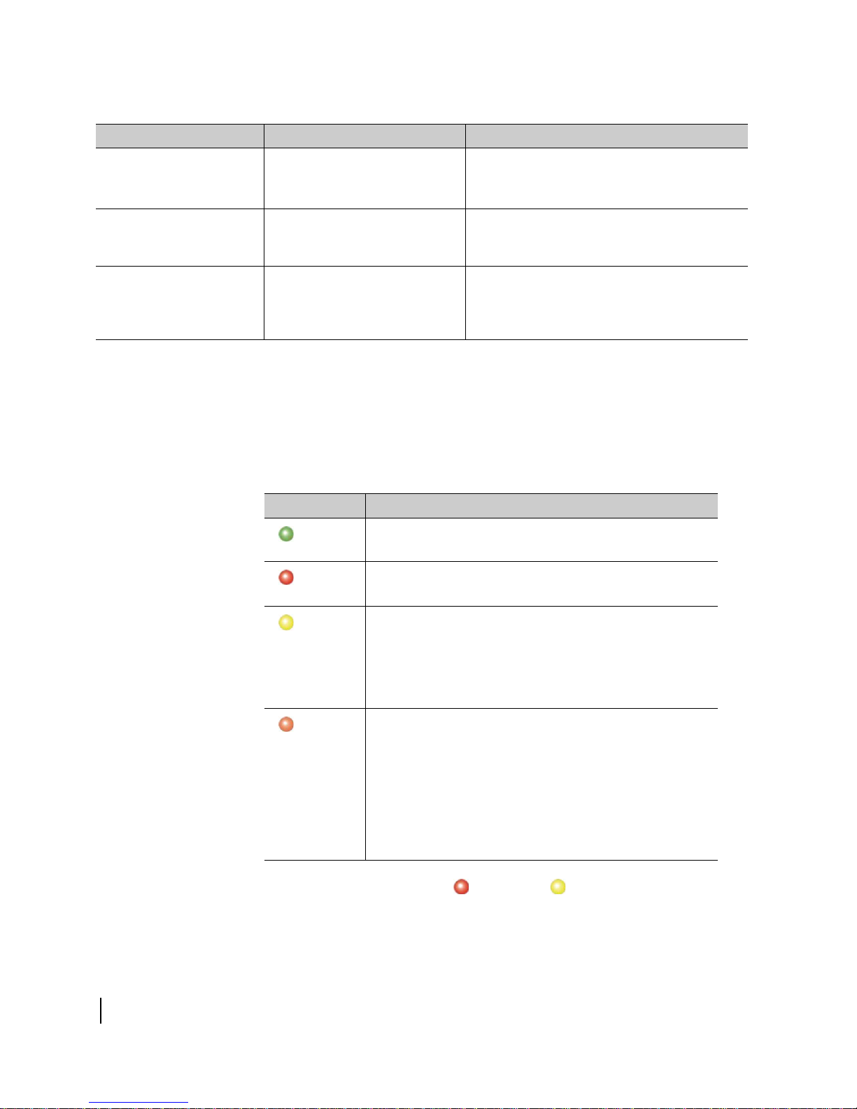
Table 2: Button links on System Control Center screens (Continued)
Button Destination Description of destination page
Reception Info Reception Information page
Displays statistics about received data. For
e information see Reception Information
mor
page on
page 28.
Transmission Info Transmission Information page Displays statistics about transmitted data. For
more information see Transmission
Information page
on page 30.
System Info System Information page Displays system information such as the
sa
tellite router's serial number and software
version. For more information see System
Information page
on page 32.
System Status button
The System Status button (only) is a status indicator as well as a link. It changes color
to indicate the satellite router's current status, as explained in Tab l e 3. To see more
detailed status information, click the System Status button to open the System Status
ge.
pa
Table 3: System Status button colors
Button color Meaning
Green
The satellite router is operating normally. (OK appears
beneath the System Status button.)
Red
Yell o w
Orange
A problem has been detected.
Performance is temporarily impaired because:
• There may be a problem with Web Acceleration.
• The router may be temporarily using a backup
onfiguration.
c
• There may be virus activity.
Degraded – The router is fully operational, but performance is temporarily impaired because:
• The daily download allowance has been exceeded. This
allowance does not apply if your service plan has no
download limit. For more information see
download allowance status
• Not all IPSec sessions are functioning. As a result, data will
ot flow between some destinations.
n
on page 34.
Checking
If the System Status button is red or yellow , look for a red flag next to
any value or values on the System Control Center information pages (those with
es listing parameters and values). The red flag indicates a problem related to the
tabl
parameter listed next to the flagged value. If the parameter name is underlined, click
22
Chapter 2 • System Control Center
1039457-0001 Revision A
the parameter name to see a message that may include helpful information,
depending on what the problem is.
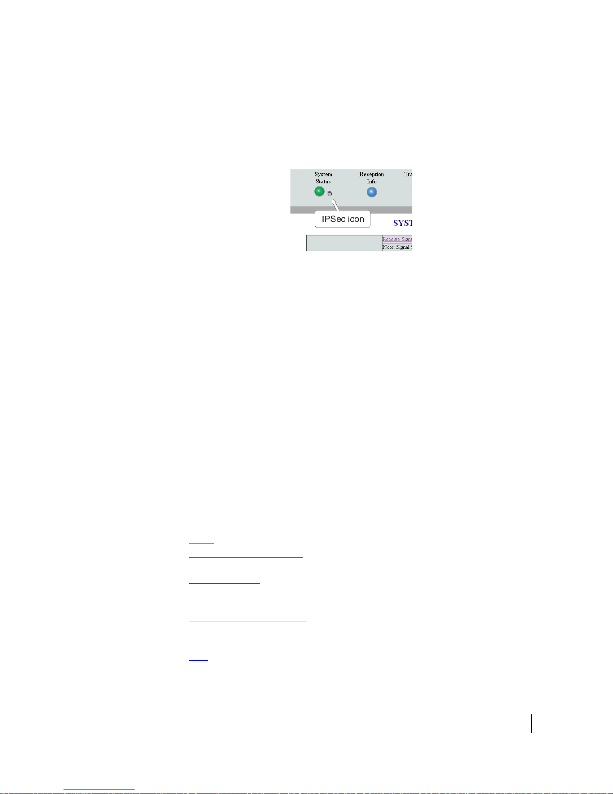
IPSec icon
An icon that looks like a small lock next to the System Status button means IPSec is
enabled. This icon is shown in Figure 8.
IPSec (Internet Protocol Security) is a set of network protocols and services that
provide security to IP networks by authenticating and encrypting each IP packet of a
data stream. IPSec-protected packets travel through a virtual tunnel or path between
two points. An IPSec tunnel is up when it has been established between two peers
and is capable of carrying traffic. If it cannot carry traffic it is down.
Figure 8: IPSec icon
When IPSec is enabled (IPSec icon present), the
configured tunnels. The status of all configured tunnels at any given time (if IPSec is
enabled) is one of the following:
tunnels are established (green System Status button).
• All
• Some
• No
tunnels are established (orange System Status button).
tunnels are established (red System Status button).
Links in the left panel
The following links appear in the left panel of each System Control Center page
(except the home page):
Note: Some of the
•
Home – Opens the System Control Center home page.
Detailed Problem Statistics – Opens a screen you can use to view statistics
•
concerning router operation. See Viewing problem-related statistics on
Connectivity Test – Opens the Connectivity Test page, which allows you to test
•
the connection between the router and the satellite. See Confirming NOC
connectivity on
Download Allowance Status – Opens the Download Allowance Status screen,
•
which shows how much remains of the daily download allowance. For details
see Checking download allowance status on
Help – Opens the Help page. Refer to the Help page, which includes a variety of
•
topics such as getting started and recommended browser settings.
se links may not appear because they are not enabled by the NOC.
page 48.
router attempts to establish all
page 60.
page 34.
Chapter 2 • System Control Center
1039457-0001 Revision A
23
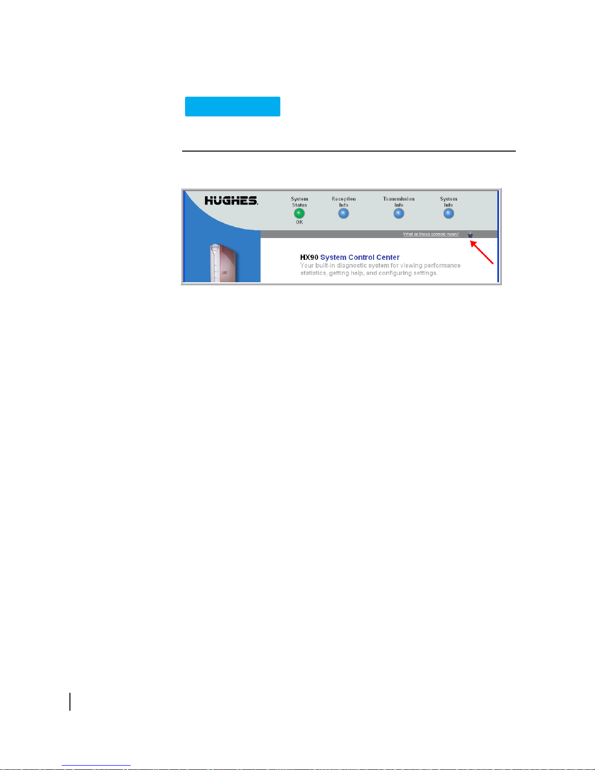
Small icon on System Control Center screens
NOTICE
The System Control Center screens include a small icon as indicated by the
arrow in
Do not click this icon unless you are a qualified technician or unless a service provider
representative instructs you to. You could cause the router to become inoperable.
Figure 9.
Figure 9: Small icon on System Control Center screens (arrow)
Status and information screens
Several of the System Control Center screens list status and operational parameters
and their current values in a tabular format. For example, the following illustration
shows the Reception Information page. The left column list the parameters, and the
right column shows the current value of the parameter listed in the left column.
Parameters are listed in this format on these screens:
stem Status page
• Sy
eception Information page
• R
ransmission Information page
• T
On any of these screens, if a parameter name or the current value of a parameter is
erlined, you can click the name or value to see an explanation of it.
und
24
Chapter 2 • System Control Center
1039457-0001 Revision A
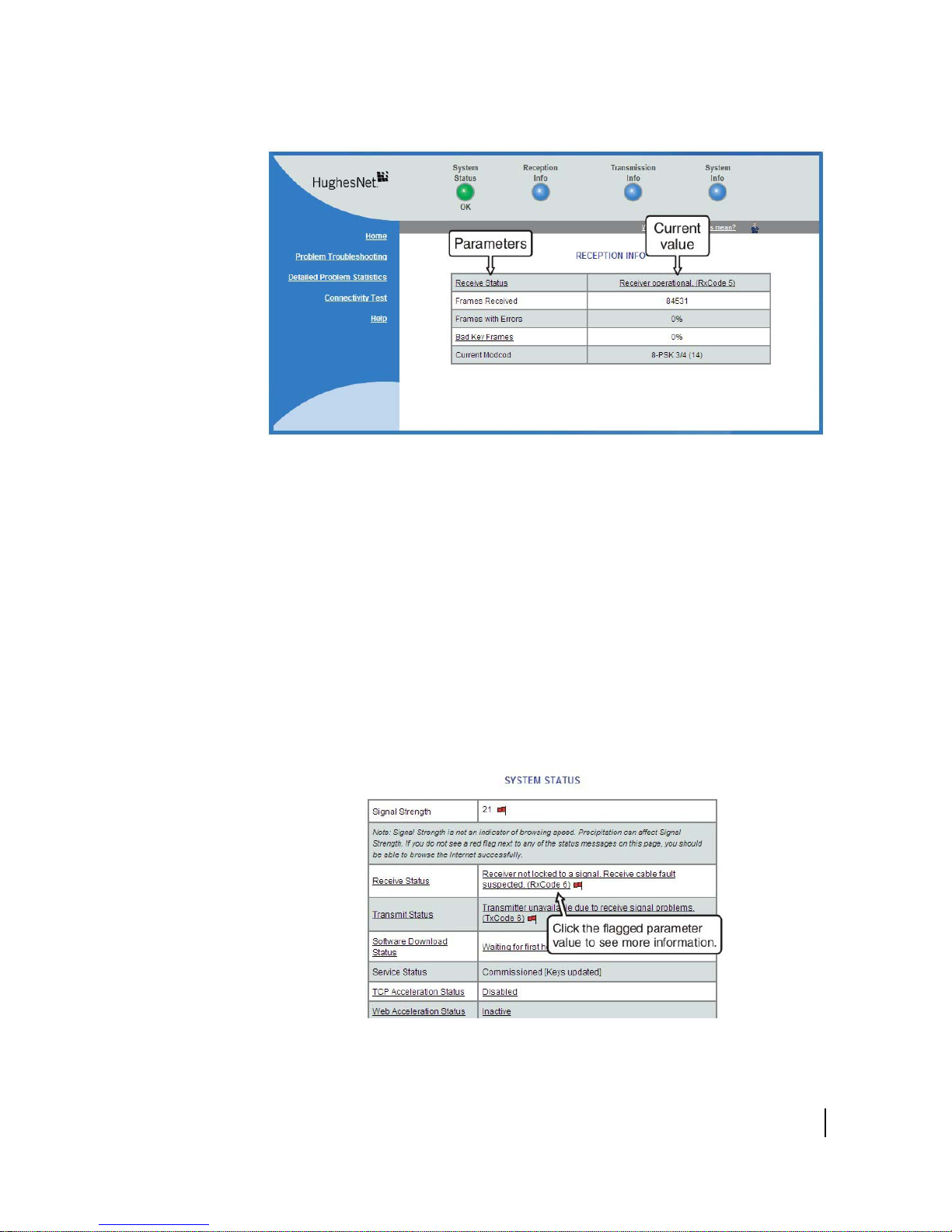
Figure 10: Format of status and information screens
The parameters listed on each screen are explained in this guide in the section for
each screen:
• System Status page on
• Reception Information page on p
• Transmission Information page on
• System Information page on p
Red flag indicator
On the status and information screens, a red flag next to a value indicates a problem
related to the parameter listed in the same row where the flagged value appears. The
flagged value appears in the right column; the parameter appears in the left column.
The value indicates the current state of the parameter.
page 26
age 28
page 30
age 32
Figure 11: Red flag problem indicator
Chapter 2 • System Control Center
1039457-0001 Revision A
25
If you see a red flag, you can click the underlined parameter value in the right column
to see additional information about the problem.
Features you may not see
You may see descriptions of certain features in the user guide that you do not see on
your System Control Center screens. This is because some features may be enabled
or disabled by the NOC depending on your service plan or your organization’s
requirements. If a feature is not enabled you will not see the screen or screens for
that feature or links to it. Features that may be enabled or disabled by the NOC are:
eb Acceleration
• W
ailed Problem Statistics
• Det
ort Forwarding
• P
• Downloa
• Br
d Allowance Status
owsing Optimization Utility
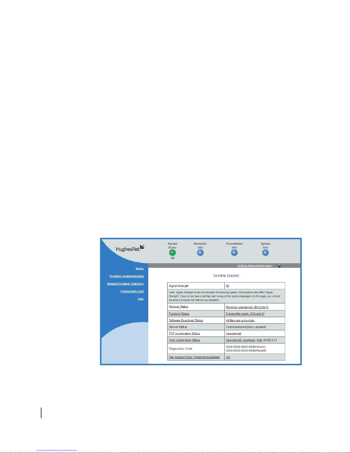
System Status page
The System Status page displays important information about the satellite router’s
operational status.
Available system status values may vary, depending on how the satellite router is
onfigured. Therefore, some options shown in Figure 12 on page 26 may not appear
c
on your System Status screen.
The System Status page and other System Control Center pages show information
may be particularly useful for advanced users and for troubleshooting.
that
Figure 12: System Status page
26
Chapter 2 • System Control Center
1039457-0001 Revision A

The parameters listed on the System Status page are explained in the following
table.
Table 4: System Status page parameters
Parameter Explanation
Signal Strength Receive signal strength. A value of 30 or less indicates a weak
signal.
Receive Status Indicates if the receive data path is operational or other status.
Click
the displayed RxCode for explanation of the displayed code.
Transmit Status Indicates if the transmit data path is
operational or other status.
Click the displayed TxCode for corresponding Help information.
Software Download Status Indicates if the satellite router’s software and configuration are up
to
date.
Service Status
Indicates if the router has been commissioned (registered with
the
system). Click the
Service History link if you want to see a
history of your customer account.
TCP Acceleration Status
Web Acceleration Status
Indicates if TCP Acceleration is operational or other status. TCP
acceler
ation improves the router’s performance.
Indicates if TCP Acceleration is operational or other status. TCP
acceler
ation improves the router’s performance.
This field is present only if the NOC operator has enabled Web
Acceler
ation on the satellite router.
Diagnostics Code This code may be useful if you need technical assistance.
Fair Access Policy Threshold
Exceeded
Indicates if you have exceeded the limit for downloads established
by your service plan. Subscribers who exceed the download limit
temporarily experience reduced download speeds.
Chapter 2 • System Control Center
1039457-0001 Revision A
27
 Loading...