

Hughes HX50, HX100 Installation Manual

Hughes
Remote Terminal Installation Guide
Models: HX50, HX100
Draft
1037106-0001
Revision B.03-Draft
August 10, 2006

Copyright © 2006 Hughes Network Systems, LLC
All rights reserved. This publication and its contents are proprietary to Hughes Network Systems,
LLC. No part of this publication may be reproduced in any form or by any means without the written
permission of Hughes Network Systems, LLC, 11717 Exploration Lane, Germantown, Maryland
20876.
Hughes Network Systems, LLC has made every effort to ensure the correctness and completeness
of the material in this document. Hughes Network Systems, LLC shall not be liable for errors
contained herein. The information in this document is subject to change without notice. Hughes
Network Systems, LLC makes no warranty of any kind with regard to this material, including, but not
limited to, the implied warranties of merchantability and fitness for a particular purpose.
Trademarks
Hughes and Hughes Network Systems are trademarks of Hughes Network Systems, LLC. All other
trademarks are the property of their respective owners.
Import ant safety information
For your safety and protection, read this entire manual before
attempting to install the remote terminal. In particular, read this
safety section carefully. Keep this safety information where you
can refer to it if necessary.
Types of warnings used in this manual
This section introduces the various types of warnings used in this
manual to alert you of possible safety hazards.
DANGER
Indicates an imminent electric shock hazard, which, if not
avoided, will result in death or serious injury.
WARNING
Indicates a potential electric shock hazard, which, if not
avoided, could result in death or serious injury.
DANGER
Indicates an imminently hazardous situation, which, if not
avoided, will result in death or serious injury.
WARNING
Indicates a potentially hazardous situation, which, if not
avoided, could result in death or serious injury.
• Important safety information
1037106-0001 Revision B.03-Draft
iii

CAUTION
Indicates a potentially hazardous situation, which, if not
avoided, may result in minor or moderate injury.
CAUTION
Indicates a situation or practice that might result in pr operty
damage.
• Important safety information
iv
1037106-0001 Revision B.03-Draft

Contents
Important safety information . . . . . . . . . . . . . . . . . . . . . iii
Types of warnings used in this manual . . . . . . . . . . . . . . . . . . . iii
About this document . . . . . . . . . . . . . . . . . . . . . . . . . . . .xv
Scope and audience . . . . . . . . . . . . . . . . . . . . . . . . . . . . . . . . . .xv
Audience profile . . . . . . . . . . . . . . . . . . . . . . . . . . . . . . . . . . .xv
Organization . . . . . . . . . . . . . . . . . . . . . . . . . . . . . . . . . . . . . . . .xv
Contact information for product users . . . . . . . . . . . . . . . . . . . xvi
Conventions . . . . . . . . . . . . . . . . . . . . . . . . . . . . . . . . . . . . . . .xvii
Related publications . . . . . . . . . . . . . . . . . . . . . . . . . . . . . . . . .xvii
Revision record. . . . . . . . . . . . . . . . . . . . . . . . . . . . . . . . . . . . xviii
Chapter 1
Introduction . . . . . . . . . . . . . . . . . . . . . . . . . . . . . . . . . . . .1
HX50 overview . . . . . . . . . . . . . . . . . . . . . . . . . . . . . . . . . . . . . .1
HX50 Hardware specifications. . . . . . . . . . . . . . . . . . . . . . . . .2
HX100 overview . . . . . . . . . . . . . . . . . . . . . . . . . . . . . . . . . . . . .4
HX100 Hardware specifications. . . . . . . . . . . . . . . . . . . . . . . .5
Supported configurations . . . . . . . . . . . . . . . . . . . . . . . . . . . . . . .6
Commissioning methods . . . . . . . . . . . . . . . . . . . . . . . . . . . . . . .8
Satellite-based commissioning . . . . . . . . . . . . . . . . . . . . . . . . .8
Manual commissioning . . . . . . . . . . . . . . . . . . . . . . . . . . . . . .9
Installation process summary . . . . . . . . . . . . . . . . . . . . . . . . . . . .9
Chapter 2
Preparing for the Installation . . . . . . . . . . . . . . . . . . . . .11
Inventorying the items required for installation . . . . . . . . . . . . .11
Confirming installer laptop and customer site requirements . . .13
Installer laptop requirements . . . . . . . . . . . . . . . . . . . . . . . . .13
Remote site requirements . . . . . . . . . . . . . . . . . . . . . . . . . . . .14
Conducting the site survey . . . . . . . . . . . . . . . . . . . . . . . . . . . . .15
Chapter 3
Installing the Hardware . . . . . . . . . . . . . . . . . . . . . . . . .17
Assembling and adjusting the antenna . . . . . . . . . . . . . . . . . . . .17
Attaching the HX50 remote terminal to the pedestal base. . . . .17
Connecting the receive and transmit cables to the remote
terminal. . . . . . . . . . . . . . . . . . . . . . . . . . . . . . . . . . . . . . . . . . . .19
Connecting component cables . . . . . . . . . . . . . . . . . . . . . . . . . .20
• Contents
1037106-0001 Revision B.03-Draft
v

Powering up and observing HX50/HX100 LEDs . . . . . . . . . . .22
Chapter 4
Commissioning the
HX50/HX100 Remote Terminal . . . . . . . . . . . . . . . . . . .25
Satellite-based commissioning . . . . . . . . . . . . . . . . . . . . . . . . . .25
Obtaining an IP address from the remote terminal. . . . . . . . .25
Uploading the SBC configuration file to the HX50/HX100 .27
Commissioning the HX50/HX100 . . . . . . . . . . . . . . . . . . . . .29
Manual commissioning . . . . . . . . . . . . . . . . . . . . . . . . . . . . . . .38
Entering manual commissioning parameters . . . . . . . . . . . . .38
Antenna pointing . . . . . . . . . . . . . . . . . . . . . . . . . . . . . . . . . .39
Chapter 5
Completing the Installation. . . . . . . . . . . . . . . . . . . . . . .43
Confirming that all files are current . . . . . . . . . . . . . . . . . . . . . .43
Connecting the HX50/HX100 remote terminal to a computer. .44
If the customer cannot use enterprise resources . . . . . . . . . . . 44
Connecting serial devices to the HX50/HX100 remote
terminal. . . . . . . . . . . . . . . . . . . . . . . . . . . . . . . . . . . . . . . . . . . .45
Printing the System Information page . . . . . . . . . . . . . . . . . . . .47
Creating a shortcut to the System Control Center . . . . . . . . . . .48
Chapter 6
Troubleshooting . . . . . . . . . . . . . . . . . . . . . . . . . . . . . . . .51
Initial troubleshooting steps . . . . . . . . . . . . . . . . . . . . . . . . . . . .51
Cannot access the System Control Center . . . . . . . . . . . . . . . . .51
Can access the System Control Center but cannot use enterprise
network resources. . . . . . . . . . . . . . . . . . . . . . . . . . . . . . . . . . . .52
Access the System Control Center . . . . . . . . . . . . . . . . . . . . .53
Confirming that the remote terminal is commissioned . . . . .53
Checking the receive signal . . . . . . . . . . . . . . . . . . . . . . . . . .53
Weather and signal strength . . . . . . . . . . . . . . . . . . . . . . . .53
Checking the transmit signal . . . . . . . . . . . . . . . . . . . . . . . . .54
Checking that TCP Acceleration is operational . . . . . . . . . . .54
Checking that Web Acceleration is operational . . . . . . . . . . .54
Checking HX System gateway connectivity . . . . . . . . . . . . .55
Enterprise network connectivity. . . . . . . . . . . . . . . . . . . . . . .56
Checking enterprise naming system settings . . . . . . . . . . . 57
Checking for viruses. . . . . . . . . . . . . . . . . . . . . . . . . . . . . . . .57
Using the remote terminal LEDs for troubleshooting . . . . . . . .58
LED appearances during normal operation . . . . . . . . . . . . . .59
Front panel LEDs . . . . . . . . . . . . . . . . . . . . . . . . . . . . . . . .59
HX50 Ethernet port LEDs . . . . . . . . . . . . . . . . . . . . . . . . .60
Fatal error indication . . . . . . . . . . . . . . . . . . . . . . . . . . . . . . .63
• Contents
vi
1037106-0001 Revision B.03-Draft

All LEDs off . . . . . . . . . . . . . . . . . . . . . . . . . . . . . . . . . . . . . .64
Checking the Power LED. . . . . . . . . . . . . . . . . . . . . . . . . . . .64
Checking the LAN LED. . . . . . . . . . . . . . . . . . . . . . . . . . . . .64
LAN LED is lit . . . . . . . . . . . . . . . . . . . . . . . . . . . . . . . . . .65
If LAN LED stays lit . . . . . . . . . . . . . . . . . . . . . . . . . . .65
If LAN LED goes dark . . . . . . . . . . . . . . . . . . . . . . . . . .65
Problems when using additional devices . . . . . . . . . . . . . . . .66
Receive LED not lit . . . . . . . . . . . . . . . . . . . . . . . . . . . . . .66
System LED not lit . . . . . . . . . . . . . . . . . . . . . . . . . . . . . . .66
Power LED not lit. . . . . . . . . . . . . . . . . . . . . . . . . . . . . . . .67
Power LED blinking. . . . . . . . . . . . . . . . . . . . . . . . . . . . . .67
Chapter 7
The System Control Center . . . . . . . . . . . . . . . . . . . . . .69
Accessing the System Control Center . . . . . . . . . . . . . . . . . . . .69
Home page . . . . . . . . . . . . . . . . . . . . . . . . . . . . . . . . . . . . . . . . .70
System indicators . . . . . . . . . . . . . . . . . . . . . . . . . . . . . . . . . .70
Links . . . . . . . . . . . . . . . . . . . . . . . . . . . . . . . . . . . . . . . . . . . .71
System Status . . . . . . . . . . . . . . . . . . . . . . . . . . . . . . . . . . .72
Test Utilities . . . . . . . . . . . . . . . . . . . . . . . . . . . . . . . . . . . .72
Help . . . . . . . . . . . . . . . . . . . . . . . . . . . . . . . . . . . . . . . . . .72
System Status page. . . . . . . . . . . . . . . . . . . . . . . . . . . . . . . . . . .73
Reception Information page . . . . . . . . . . . . . . . . . . . . . . . . . . . .74
Receive status messages . . . . . . . . . . . . . . . . . . . . . . . . . . . . .75
Transmission Information page . . . . . . . . . . . . . . . . . . . . . . . . .77
Transmit status messages . . . . . . . . . . . . . . . . . . . . . . . . . . . .78
System Information page . . . . . . . . . . . . . . . . . . . . . . . . . . . . . .84
Connectivity Test page. . . . . . . . . . . . . . . . . . . . . . . . . . . . . . . .86
Help page . . . . . . . . . . . . . . . . . . . . . . . . . . . . . . . . . . . . . . . . . .87
Appendix A
Configuring a Windows computer to support DHCP .89
Windows XP. . . . . . . . . . . . . . . . . . . . . . . . . . . . . . . . . . . . . .89
Windows 2000 . . . . . . . . . . . . . . . . . . . . . . . . . . . . . . . . . . . .92
Windows 98SE and Me . . . . . . . . . . . . . . . . . . . . . . . . . . . . .94
Appendix B
Updating the remote terminal software. . . . . . . . . . . . .97
Saving the utility on the installer laptop. . . . . . . . . . . . . . . . . . .97
Configuring the TCP/IP properties on the installer laptop. . . . .98
Windows XP. . . . . . . . . . . . . . . . . . . . . . . . . . . . . . . . . . . . . .98
Windows 2000 . . . . . . . . . . . . . . . . . . . . . . . . . . . . . . . . . . .101
Windows 98 SE and Me . . . . . . . . . . . . . . . . . . . . . . . . . . . .103
Updating the fallback.bin file. . . . . . . . . . . . . . . . . . . . . . . . . .105
Troubleshooting . . . . . . . . . . . . . . . . . . . . . . . . . . . . . . . . . . . .106
• Contents
1037106-0001 Revision B.03-Draft
vii

Appendix C
Disabling a Web browser’s proxy connection. . . . . . .107
Internet Explorer. . . . . . . . . . . . . . . . . . . . . . . . . . . . . . . . . . . .107
Netscape . . . . . . . . . . . . . . . . . . . . . . . . . . . . . . . . . . . . . . . . . .108
Appendix D
Conforming with standards and directives . . . . . . . . .111
Safety – operating conditions for Canada . . . . . . . . . . . . . . . .112
Repairs in Canada. . . . . . . . . . . . . . . . . . . . . . . . . . . . . . . . .112
Electromagnetic compatibility (EMI) . . . . . . . . . . . . . . . . . . .113
FCC Part 15 . . . . . . . . . . . . . . . . . . . . . . . . . . . . . . . . . . . . .113
Canada Class B warning. . . . . . . . . . . . . . . . . . . . . . . . . . . .114
R&TTE (EU) . . . . . . . . . . . . . . . . . . . . . . . . . . . . . . . . . . . .114
Telecommunications standards . . . . . . . . . . . . . . . . . . . . . . . .114
IPoS . . . . . . . . . . . . . . . . . . . . . . . . . . . . . . . . . . . . . . . . . . .114
FCC Part 68 . . . . . . . . . . . . . . . . . . . . . . . . . . . . . . . . . . . . .114
Ringer equivalence number (REN) . . . . . . . . . . . . . . . . . . .115
Repairs in the United States . . . . . . . . . . . . . . . . . . . . . . . . .116
Canada – equipment attachment limitations. . . . . . . . . . . . .116
Acronyms and abbreviations . . . . . . . . . . . . . . . . . . . .117
Index . . . . . . . . . . . . . . . . . . . . . . . . . . . . . . . . . . . . . . . .119
viii
• Contents
1037106-0001 Revision B.03-Draft

Figures
Chapter 1
1. HX50 Remote terminal. . . . . . . . . . . . . . . . . . . . . . . . . . . . . . . . . . . . . . . . . . . . .1
2. HX50 rear panel . . . . . . . . . . . . . . . . . . . . . . . . . . . . . . . . . . . . . . . . . . . . . . . . . .2
3. HX100 Remote terminal. . . . . . . . . . . . . . . . . . . . . . . . . . . . . . . . . . . . . . . . . . . .4
4. HX100 rear panel . . . . . . . . . . . . . . . . . . . . . . . . . . . . . . . . . . . . . . . . . . . . . . . . .4
5. Single-host configuration EPS . . . . . . . . . . . . . . . . . . . . . . . . . . . . . . . . . . . . . . .6
6. Multiple-host configuration: Ethernet hub or router (wired LAN) . . . . . . . . . . .7
7. Multiple-host configuration: wireless base station (wireless LAN). . . . . . . . . . .8
Chapter 2
8. HX50 installation kit components . . . . . . . . . . . . . . . . . . . . . . . . . . . . . . . . . . .12
9. HX100 installation kit components . . . . . . . . . . . . . . . . . . . . . . . . . . . . . . . . . .13
Chapter 3
10. Attaching the HX50 to the pedestal base . . . . . . . . . . . . . . . . . . . . . . . . . . . . . .18
11. Connecting the receive and transmit cables to the HX50 remote terminal . . . . 19
12. Connecting the receive and transmit cables to the HX100 remote terminal . . . 19
13. Connecting HX50 component cables . . . . . . . . . . . . . . . . . . . . . . . . . . . . . . . . .21
14. Connecting HX100 component cables . . . . . . . . . . . . . . . . . . . . . . . . . . . . . . . .22
Chapter 4
15. Successful ping . . . . . . . . . . . . . . . . . . . . . . . . . . . . . . . . . . . . . . . . . . . . . . . . . .26
16. Failed ping . . . . . . . . . . . . . . . . . . . . . . . . . . . . . . . . . . . . . . . . . . . . . . . . . . . . .27
17. HX100 Broadband Satellite Setup screen . . . . . . . . . . . . . . . . . . . . . . . . . . . . .28
18. Antenna Location screen . . . . . . . . . . . . . . . . . . . . . . . . . . . . . . . . . . . . . . . . . .29
19. Entering location manually. . . . . . . . . . . . . . . . . . . . . . . . . . . . . . . . . . . . . . . . .30
20. Selecting the satellite and transponder . . . . . . . . . . . . . . . . . . . . . . . . . . . . . . . .31
21. Entering satellite parameters manually. . . . . . . . . . . . . . . . . . . . . . . . . . . . . . . .32
22. Verifying satellite parameters. . . . . . . . . . . . . . . . . . . . . . . . . . . . . . . . . . . . . . .33
23. Selecting the transmit radio . . . . . . . . . . . . . . . . . . . . . . . . . . . . . . . . . . . . . . . .34
24. Receive pointing . . . . . . . . . . . . . . . . . . . . . . . . . . . . . . . . . . . . . . . . . . . . . . . . .35
25. Accessing the registration server . . . . . . . . . . . . . . . . . . . . . . . . . . . . . . . . . . . .36
26. Accepting the security certificate . . . . . . . . . . . . . . . . . . . . . . . . . . . . . . . . . . . .36
27. Registering a remote terminal (enterprise customer) – entering site ID. . . . . . .37
28. Manual Commissioning Page. . . . . . . . . . . . . . . . . . . . . . . . . . . . . . . . . . . . . . .39
29. Antenna pointing screen . . . . . . . . . . . . . . . . . . . . . . . . . . . . . . . . . . . . . . . . . . .40
30. Receive pointing . . . . . . . . . . . . . . . . . . . . . . . . . . . . . . . . . . . . . . . . . . . . . . . . .41
• Figures
1037106-0001 Revision B.03-Draft
ix

Chapter 5
31. Final configuration . . . . . . . . . . . . . . . . . . . . . . . . . . . . . . . . . . . . . . . . . . . . . . .44
32. Connecting a serial device to the HX50 . . . . . . . . . . . . . . . . . . . . . . . . . . . . . . .46
33. Connecting a serial device to the HX100 . . . . . . . . . . . . . . . . . . . . . . . . . . . . . .47
34. Creating a shortcut to the System Control Center . . . . . . . . . . . . . . . . . . . . . . .48
35. Entering the System Control Center URL in the Create Shortcut window . . . .49
36. Entering the name of the shortcut. . . . . . . . . . . . . . . . . . . . . . . . . . . . . . . . . . . .49
Chapter 6
37. HX50 Remote terminal LEDs . . . . . . . . . . . . . . . . . . . . . . . . . . . . . . . . . . . . . .58
38. HX100 Remote terminal LEDs . . . . . . . . . . . . . . . . . . . . . . . . . . . . . . . . . . . . .59
39. Ethernet port LED operation . . . . . . . . . . . . . . . . . . . . . . . . . . . . . . . . . . . . . . .61
40. HX50 power and cable connections . . . . . . . . . . . . . . . . . . . . . . . . . . . . . . . . . .62
41. HX100 power and cable connections . . . . . . . . . . . . . . . . . . . . . . . . . . . . . . . . .63
Chapter 7
42. System Control Center home page . . . . . . . . . . . . . . . . . . . . . . . . . . . . . . . . . . .70
43. System indicators . . . . . . . . . . . . . . . . . . . . . . . . . . . . . . . . . . . . . . . . . . . . . . . .71
44. System Status indicator reporting a problem . . . . . . . . . . . . . . . . . . . . . . . . . . .71
45. System Status page . . . . . . . . . . . . . . . . . . . . . . . . . . . . . . . . . . . . . . . . . . . . . . .73
46. Reception Information page . . . . . . . . . . . . . . . . . . . . . . . . . . . . . . . . . . . . . . . .74
47. Transmission Information page . . . . . . . . . . . . . . . . . . . . . . . . . . . . . . . . . . . . .77
48. System Information page . . . . . . . . . . . . . . . . . . . . . . . . . . . . . . . . . . . . . . . . . .84
49. Connectivity Test page . . . . . . . . . . . . . . . . . . . . . . . . . . . . . . . . . . . . . . . . . . . .86
50. Successful connectivity test . . . . . . . . . . . . . . . . . . . . . . . . . . . . . . . . . . . . . . . .86
51. Help page . . . . . . . . . . . . . . . . . . . . . . . . . . . . . . . . . . . . . . . . . . . . . . . . . . . . . .87
Appendix A
52. Network Connections - Windows XP . . . . . . . . . . . . . . . . . . . . . . . . . . . . . . . .89
53. Local Area Connection Properties - Windows XP. . . . . . . . . . . . . . . . . . . . . . .90
54. Internet Protocol Properties - Windows XP . . . . . . . . . . . . . . . . . . . . . . . . . . . .91
55. Network and Dialup Connections - Windows 2000. . . . . . . . . . . . . . . . . . . . . .92
56. Local Area Connection Properties - Windows 2000 . . . . . . . . . . . . . . . . . . . . .92
57. Internet Protocol Properties - Windows 2000 . . . . . . . . . . . . . . . . . . . . . . . . . .93
58. Control Panel - Windows 98SE and Me. . . . . . . . . . . . . . . . . . . . . . . . . . . . . . .94
59. Network window - Windows 98SE and Me. . . . . . . . . . . . . . . . . . . . . . . . . . . .95
60. TCP/IP Properties - Windows 98SE and Me . . . . . . . . . . . . . . . . . . . . . . . . . . .95
61. Gateway tab - Windows 98SE and Me. . . . . . . . . . . . . . . . . . . . . . . . . . . . . . . .96
Appendix B
62. Saving the Fallback Updater utility on the installer laptop . . . . . . . . . . . . . . . . 97
63. Network Connections - Windows XP . . . . . . . . . . . . . . . . . . . . . . . . . . . . . . . .99
64. Local Area Connection Properties - Windows XP. . . . . . . . . . . . . . . . . . . . . .100
• Figures
x
1037106-0001 Revision B.03-Draft

65. Internet Protocol Properties - Windows XP . . . . . . . . . . . . . . . . . . . . . . . . . . .100
66. Network and Dial-up Connections - Windows 2000 . . . . . . . . . . . . . . . . . . . .101
67. Local Area Connection Properties - Windows 2000 . . . . . . . . . . . . . . . . . . . .102
68. Internet Protocol Properties - Windows 2000 . . . . . . . . . . . . . . . . . . . . . . . . .102
69. Control Panel - Windows 98SE and Me. . . . . . . . . . . . . . . . . . . . . . . . . . . . . .103
70. Network window - Windows 98SE and Me. . . . . . . . . . . . . . . . . . . . . . . . . . .104
71. TCP/IP Properties - Windows 98SE and Me . . . . . . . . . . . . . . . . . . . . . . . . . .104
72. Entering the remote terminal IP address. . . . . . . . . . . . . . . . . . . . . . . . . . . . . .105
Appendix C
73. Selecting the Connections tab - IE . . . . . . . . . . . . . . . . . . . . . . . . . . . . . . . . . .107
74. Accessing LAN settings - IE . . . . . . . . . . . . . . . . . . . . . . . . . . . . . . . . . . . . . .108
75. Accessing proxy settings - Netscape . . . . . . . . . . . . . . . . . . . . . . . . . . . . . . . .108
Appendix D
76. IPoS symbol . . . . . . . . . . . . . . . . . . . . . . . . . . . . . . . . . . . . . . . . . . . . . . . . . . .114
• Figures
1037106-0001 Revision B.03-Draft
xi

xii
• Figures
1037106-0001 Revision B.03-Draft

Tables
Chapter 1
1. HX50 equipment specifications . . . . . . . . . . . . . . . . . . . . . . . . . . . . . . . . . . . . . .2
2. HX100 equipment specifications . . . . . . . . . . . . . . . . . . . . . . . . . . . . . . . . . . . . .5
Chapter 6
3. Front panel LED operation . . . . . . . . . . . . . . . . . . . . . . . . . . . . . . . . . . . . . . . . .60
Chapter 7
4. Receive code (RxCode) messages and corrective actions . . . . . . . . . . . . . . . . .75
5. Transmit code (TxCode) messages and corrective actions . . . . . . . . . . . . . . . .78
Appendix D
6. HX50 and HX100 standards compliance . . . . . . . . . . . . . . . . . . . . . . . . . . . . .111
• Tables
1037106-0001 Revision B.03-Draft
xiii

xiv
• Tables
1037106-0001 Revision B.03-Draft

About this document
Scope and audience
Audience profile
This manual describes installing, commissioning,
troubleshooting, and servicing HX50 and HX100 remote
terminals. The manual also provides additional reference
information for the installation and operation of the remote
terminals.
While the HX50 and HX100 share a basic set of features and
functionalities, the HX100 offers these additional features over
the HX50:
• rack mounting kit
• higher speed inroutes
The HX100 is packaged in a thin horizontal enclosure and
includes a mounting kit for optional rack installation. The HX50
has a smaller, more portable desktop form-factor and includes an
attachable pedestal base for optional vertical mounting.
This manual is intended for use by the following audiences:
• Professional installers
• Installer trainers, who prepare separate instructions for the
installers
Organization
This manual is organized into the following chapters and
appendices:
Chapter 1 – Introduction gives an overview of the HX50/HX100
remote terminal.
Chapter 2 – Preparing for the Installation discusses steps that
must be completed before installing an HX50 or HX100 remote
terminal.
Chapter 3 – Installing the Hardware explains how to assemble
and install HX50 and HX100 remote terminals.
Chapter 4 – Commissioning the HX50/HX100 Remote Terminal
explains how to register for use the HX50/HX100, either
manually or using a satellite-based method.
• About this document
1037106-0001 Revision B.03-Draft
xv

Chapter 5 – Completing the Installation discusses those tasks that
must be completed after the remote terminal is installed and
commissioned to make it fully operational.
Chapter 6 – Troubleshooting describes procedures for correcting
problems encountered while installing or commissioning remote
terminals.
Chapter 7 – The System Control Center describes the System
Control Center, an embedded web application that provides
remote terminal status and configuration information to the user.
Appendix A – Configuring a Windows computer to support
DHCP explains how to configure a PC connected to the remote
terminal to use the Dynamic Host Control Protocol (DHCP),
which is used to manage the assignment of IP addresses to
devices on the remote LAN.
Appendix B – Updating the remote terminal software explains
how to use the Fallback Updater utility to update the
fallback.bin file on an HX50/HX100 remote terminal.
Appendix C – Disabling a Web browser’s proxy connection
explains how to disable proxy server settings for Internet
Explorer and Netscape.
Contact information for product users
Appendix D – Conforming with standards and directives lists the
standards and directives that apply to HX50 and HX100
terminals.
This manual also contains a safety summary, a list of
abbreviations and acronyms, and an index.
For warranty or repair support, your contact information varies
depending on your location. If you need service, warranty or
repair support, please contact your customer service
representative in accordance with your service agreement.
%%BUSINESS GROUP REVIEWER: PLEASE VERIFY
THAT THIS IS THE CORRECT CONTACT
INFORMATION??%%
xvi
• About this document
1037106-0001 Revision B.03-Draft

Conventions
This manual follows the typographical conventions shown below
to help clarify instructions:
Example Explanation
Click Exit.
The system displays the following:
Are you ready?
Ty p e exit
Enter a value in the Time field.
Retrieve the following file:
O:\template\techman_r3
Press ALT+V to view the menu.
Select the Edit menu.
Go to Edit → Spelling Checker
Indicates the names of command
buttons that execute an action.
Indicates all system messages
and prompts as the system
displays them.
Indicates operator input.
Indicates the names of fields on
windows.
Indicates file names or file paths
referenced in the manual.
Indicates function or keyboard
keys. Press two keys
simultaneously—in this case, Alt
and V.
Indicates the names of menu bar
options on a software screen.
Indicates a menu/submenu
sequence for selecting an action
or option
Related publications
The following documents provide more detailed information
about HX system and System gateway (GTWY) components.
• HX System Overview (1037105-0001)
• HX System Gateway (GTWY) Installation Manual,
Volume 1: Overview and Rack Installation (1036936-0001)
• HX System Gateway (GTWY) Installation Manual,
Volume 2: Component Configuration (1036937-0001)
• HX System Gateway (GTWY) Operations and
Troubleshooting Manual, Volume 1: Remote Terminal
Operations (1036938-0001)
• HX System Gateway (GTWY) Operations and
Troubleshooting Manual, Volume 2: GTWY Operations
(1036939-0001)
• HX System Gateway (GTWY) Reference Manual,
Volume 1: UEM References (1036940-0001)
• HX System Gateway (GTWY) Reference Manual,
Volume 2: Other Native Interface References
(1036941-0001)
• Remote Terminal User Guide, Models HX50, HX100
(1036942)
• About this document
1037106-0001 Revision B.03-Draft
xvii
Revision record
Revision Date of issue Scope
A May 31, 2006 Production Release
B.01 July 25, 2006 First draft of Revision B
B.02 August 7, 2006 Second draft of Revision B
B.03 August 10, 2006 Third draft of revision B
(Bookmarks inspection)
xviii
• About this document
1037106-0001 Revision B.03-Draft

Chapter 1
Introduction
The HX50 and HX100 are the two remote terminals that can be
used with an HX system. This chapter discusses these general
HX50 and HX100 remote terminal topics:
• HX50 overview on page 1.
• HX100 overview on page 4.
• Supported configurations on page 6
• Commissioning methods on page 8
• Installation process summary on page 9
HX50 overview
The HX50 remote terminal, shown in Figure 1, is a very small
aperture terminal (VSAT) that provides satellite connectivity
between a remote IP device such as a computer, POS device, or
small LAN, and the HX system gateway (GTWY). The HX50 is
designed for desktop use, either resting horizontally or mounted
vertically using a provided pedestal base. Like the HX100, the
HX50 is equipped with a serial port, two Ethernet ports, a
telephone line port, and an internal modem, as shown in
Figure 2.
Figure 1: HX50 Remote terminal
1037106-0001 Revision B.03-Draft
Chapter 1 • Introduction
1
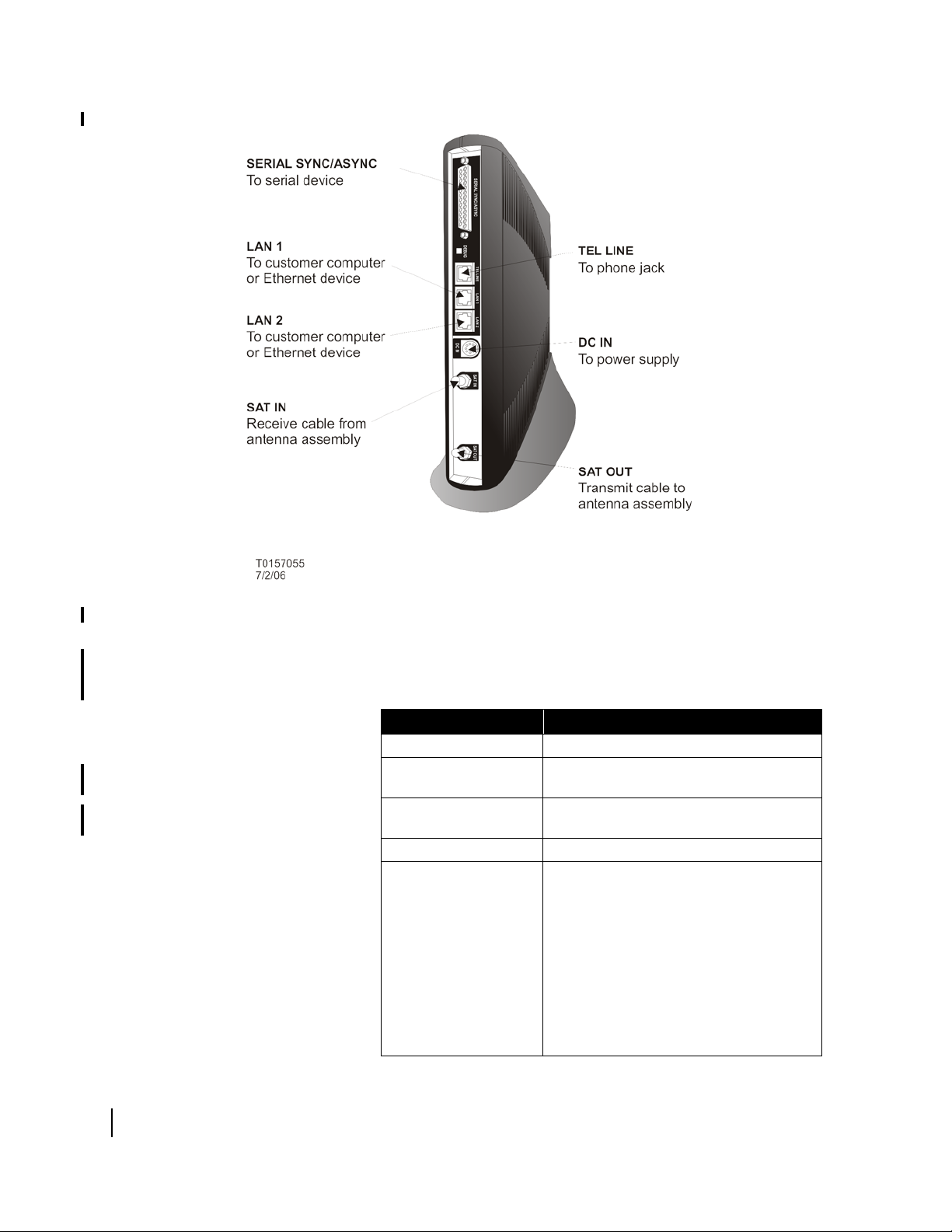
Figure 2: HX50 rear panel
HX50 Hardware
specifications
Refer to Table 1 for HX50 equipment specifications.
Table 1: HX50 equipment specifications
Product Element Specification
Weight 2.4 lb (1.089 kg)
Width 1.7 in (4.32 cm)
4.5 in (11.43 cm) with pedestal base
Height 9.5 in (24.13 cm)
9.75 in (24.77 cm) with pedestal base
Depth 10.5 in (26.67 cm)
AC/DC power supply for
1 W radio (64 W)
Electrical requirements:
• Input line voltage
• Input line frequency
• Rated power
consumption
Power cord
PN 1031105-0001
100 - 240 V - 2A max
50-60 HZ AC
64 W
Detachable power cord for 110 VAC outlet
type
Chapter 1 • Introduction
2
1037106-0001 Revision B.03-Draft

Table 1: HX50 equipment specifications (Continued)
Product Element Specification
AC/DC power supply for
2 W radio (64W)
Electrical requirements:
• Input line voltage
• Input line frequency
• Rated power
consumption
PN 1031105-0001
100 - 240 V - 2A max
50-60 HZ AC
64 W
Power cord
DC/DC power supply
Electrical requirements:
• Input line voltage
• Rated power
consumption
Power cord
Safe operating temperature range
Safe operating humidity 5% to 95% non-condensing
Safe altitude 10,000 ft.
Cooling method Convection
Interfaces/ports • Two Ethernet ports supporting 10BaseT
Main processor 133 Mhz, MIPS
Detachable power cord for 110 VAC outlet
type
PN 1033554-0001
12.7 - 25 V - 10A max
64 W
Detachable power input cables and
connector
0 to 40 degrees C (above 5000 feet
altitude, reduce maximum temperature by
1 degree C per 1000 feet)
or 100BaseT operation, RJ45-switched
• Telephone line port
• Serial port, DTE/DCE RS-232, which
supports the following protocols:
– VISA (Veriphone 3200 and 3300) (the
asynchronous protocol of Vanguard
International Service Association credit
card)
– X.25 International Telecommunication
Union-Telecommunication
Standardization Sector (ITU-T)
protocol standard for WAN
communications)
– XPAD (X.25 Packet
Assembler/Disassembler)
– DSPAD (IBM 3270 Display System
Protocol)
– SDLC (Synchronous Data Link
Control)
– LLC (Logical Link Control)
Chapter 1 • Introduction
1037106-0001 Revision B.03-Draft
3
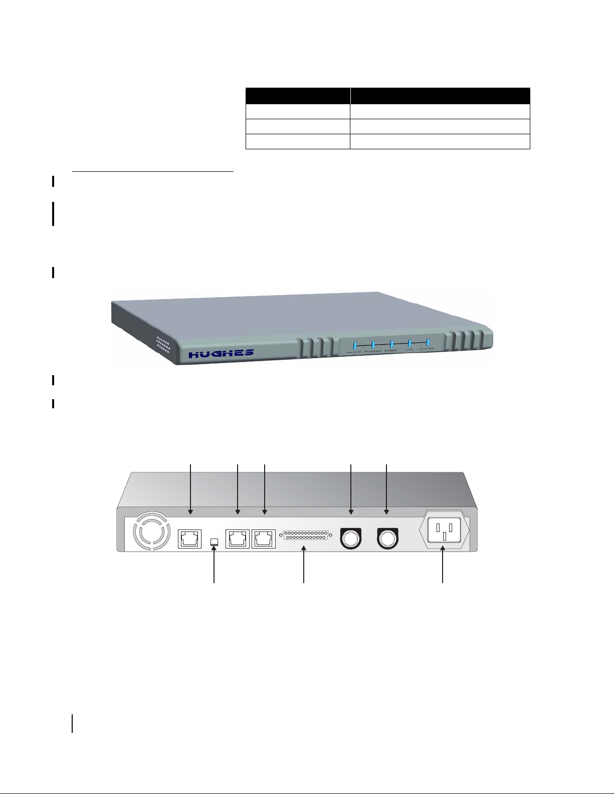
Table 1: HX50 equipment specifications (Continued)
Product Element Specification
Main memory 64MB
Flash memory 16MB
Protocol Support TCP/IP protocol suite
HX100 overview
TEL LINE
To phone
jack
The HX100 remote terminal, shown in Figure 3, is a
rack-mounted very small aperture terminal (VSAT) that provides
satellite connectivity between a remote IP device such as a
computer, POS device, or small LAN, and the HX system
gateway (GTWY). The HX100 is suitable for both rack-mounted
or desktop use. As shown in
Figure 4, the HX100 is equipped
with a serial port, two Ethernet ports, a telephone line port, and an
internal modem.
Figure 3: HX100 Remote terminal
LAN 1/LAN 2
To customer computer
or Ethernet device
SAT IN
Receive cable
from antenna
assembly
SAT OUT
Transmit cable
from antenna
assembly
G-28579 C 05/31/06
Chapter 1 • Introduction
4
1037106-0001 Revision B.03-Draft
DEBUG
J3-LAN 1J2-DEBUGJ1-TEL J4-LAN 2
J5-SERIAL SYNC/ASYNC
SERIAL SYNC/ASYNC
To Serial device
Figure 4: HX100 rear panel
J6-SAT IN
J8-POWER
J7-SAT OUT
POWER
to power supply

HX100 Hardware
specifications
Refer to Table 2 for HX100 equipment specifications.
Table 2: HX100 equipment specifications
Product Element Specification
Height 1.75 in (4.45 cm)
Width 19 in (48.26 cm)
Depth 18 in (45.72 cm)
Weight 4 lb (1.814 kg)
Electrical requirements:
• Input line voltage
• Input line frequency
• Rated power
consumption
100 - 240 V - 2A max
50-60 HZ AC
64 W
Power cord
Safe operating temperature range
Safe operating humidity 5% to 95% non-condensing
Safe altitude 10,000 ft.
Cooling method Forced air
Interfaces/ports • Two Ethernet ports supporting 10BaseT
Main processor 133 Mhz, MIPS
Main memory 64MB
Flash memory 16MB
Protocol Support TCP/IP protocol suite
Detachable power cord for 110 VAC outlet
type
0 to 40 degrees C (above 5000 feet
altitude, reduce maximum temperature by
1 degree C per 1000 feet)
or 100BaseT operation, RJ45-switched
• Telephone line port
• Serial port, DTE/DCE RS-232, which
supports the following protocols:
– VISA (Veriphone 3200 and 3300) (the
asynchronous protocol of Vanguard
International Service Association credit
card)
– X.25 International Telecommunication
Union-Telecommunication
Standardization Sector (ITU-T)
protocol standard for wide area
network (WAN) communications
– XPAD (X.25 Packet
Assembler/Disassembler)
– DSPAD (IBM 3270 Display System
Protocol)
– SDLC (Synchronous Data Link
Control)
– LLC (Logical Link Control)
Chapter 1 • Introduction
1037106-0001 Revision B.03-Draft
5
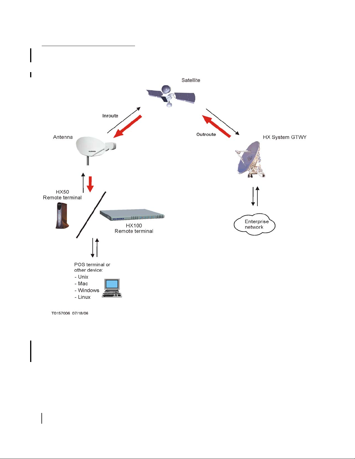
Supported configurations
In a single-host configuration, such as the one shown in Figure 5,
the HX50/HX100 is connected directly to the host.
Chapter 1 • Introduction
6
1037106-0001 Revision B.03-Draft
Figure 5: Single-host configuration EPS
In a multiple-host configuration, the hosts on the local area
network (LAN) share satellite connectivity to an enterprise
network through an Ethernet hub, router, or wireless base station
and the remote terminal is connected to the hub, router, or
wireless base station.
configuration that includes an Ethernet hub or router. Figure 7
Figure 6 shows a multiple-host
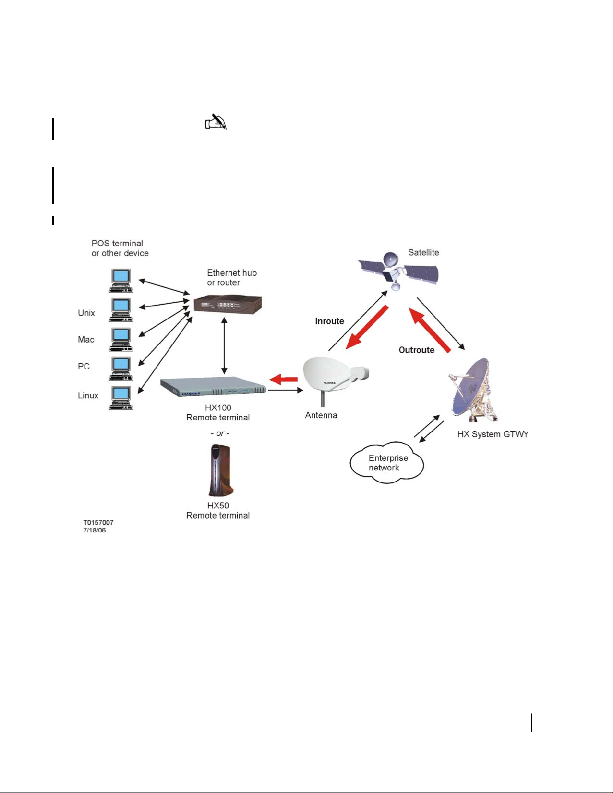
shows a multiple-host configuration that includes a wireless base
station.
Note: Hughes is not responsible for networking equipment
attached to the remote terminal.
The graphics in this section are intended for illustrative purposes
only. Procedures for connecting components to the HX50 and
HX100 remote terminals are discussed in
Chapter 5 – Completing
the Installation.
Figure 6: Multiple-host configuration: Ethernet hub or router (wired LAN)
Chapter 1 • Introduction
1037106-0001 Revision B.03-Draft
7

Figure 7: Multiple-host configuration: wireless base station (wireless LAN)
Commissioning methods
Satellite-based
commissioning
Chapter 1 • Introduction
8
1037106-0001 Revision B.03-Draft
Commissioning is the process of registering a remote terminal
for service. There are three methods available to commission a
remote terminal:
• Satellite-based commissioning (SBC)
• Manual commissioning
For satellite-based commissioning (SBC), the installer uses a
web-based interface on the remote terminal to complete the
commissioning process. Satellite-based commissioning is the
preferred commissioning method.
HX50/HX100 remote terminals contain an SBC configuration file
(
sbc.cfg), that provides satellite information that SBC and the
auto-commissioning server (ACS) use during the commissioning

process. Occasionally, new satellites are activated to support
system service. Therefore, installers may be required to either
upload an
sbc.cfg file to the remote terminal prior to
installation or to manually enter satellite parameters during
installation.
If a new sbc.cfg file is available when a satellite is activated,
the installer must obtain the file (for example, by downloading it
from an installation support FTP or web site) and save it on the
installer laptop prior to commissioning. Once the commissioning
process has been completed, the
sbc.cfg is uploaded to the
remote terminal.
If there is no new sbc.cfg file available, the installer will
receive the new satellite parameters either in a technical update
e-mail or an installation specification. In either case, the installer
enters the new satellite parameters manually.
Note: If the service provider%%NEED REPLACEMENT
FOR “SERVICE PROVIDER”%% supplies an sbc.cfg file,
you must upload the file to the remote terminal by completing the
procedures in
HX50/HX100 on page 27.
Uploading the SBC configuration file to the
Manual commissioning
Installation process summary
Satellite-based commissioning procedures are provided in
Chapter 4 – Commissioning the HX50/HX100 Remote Terminal.
The installer should only commission a terminal manually if
instructed to do so by the service provider. For manual
commissioning, the installer enters the appropriate configuration
parameters on the Manual Commissioning page of the terminal’s
web-based interface, then uses the interface to fine-point the
antenna.
Manual commissioning procedures are provided in
Chapter 4 – Commissioning the HX50/HX100 Remote Terminal.
The procedure for installing an HX50 or HX100 remote terminal
consists of the following steps:
• Preparing for the installation (Chapter 2 ):
– Inventorying the items required for installation
– Confirming that the customer’s computer meets the
requirements for using the service (not required for
International or enterprise customers)
– Conducting the site survey
• Installing the hardware (Chapter 3 ):
1037106-0001 Revision B.03-Draft
Chapter 1 • Introduction
9

– Assembling and adjusting the antenna
– Connecting component cables
– Powering up and observing remote terminal LEDs
• Commissioning the remote terminal (Chapter 4 ) using one
of the following methods:
– Satellite-based commissioning
– Dial-up commissioning
– Manual commissioning
• Completing the installation (Chapter 5 ):
– Confirming that all files are current
– Connecting the remote terminal to the customer’s
computer
– Connecting serial devices to the remote terminal
– Printing the System Information page (may not be required
for International or enterprise customers)
– Creating a shortcut to the System Control Center (may not
be required for International or enterprise customers)
10
Chapter 1 • Introduction
1037106-0001 Revision B.03-Draft

Chapter 2
Preparing for the Installation
This chapter discusses the following tasks:
• Inventorying the items required for installation on page 11
• Confirming installer laptop and customer site requirements
on page 13
• Conducting the site survey on page 15
Note: In the following sections, installer laptop refers to the
computer, typically a laptop, used to connect to and commission a
remote terminal.
Inventorying the items required for installation
To install an HX50 or HX100 remote terminal, first ensure that
you have all of the items in the remote terminal installation kit.
Chapter 2 • Preparing for the Installation
1037106-0001 Revision B.03-Draft
11
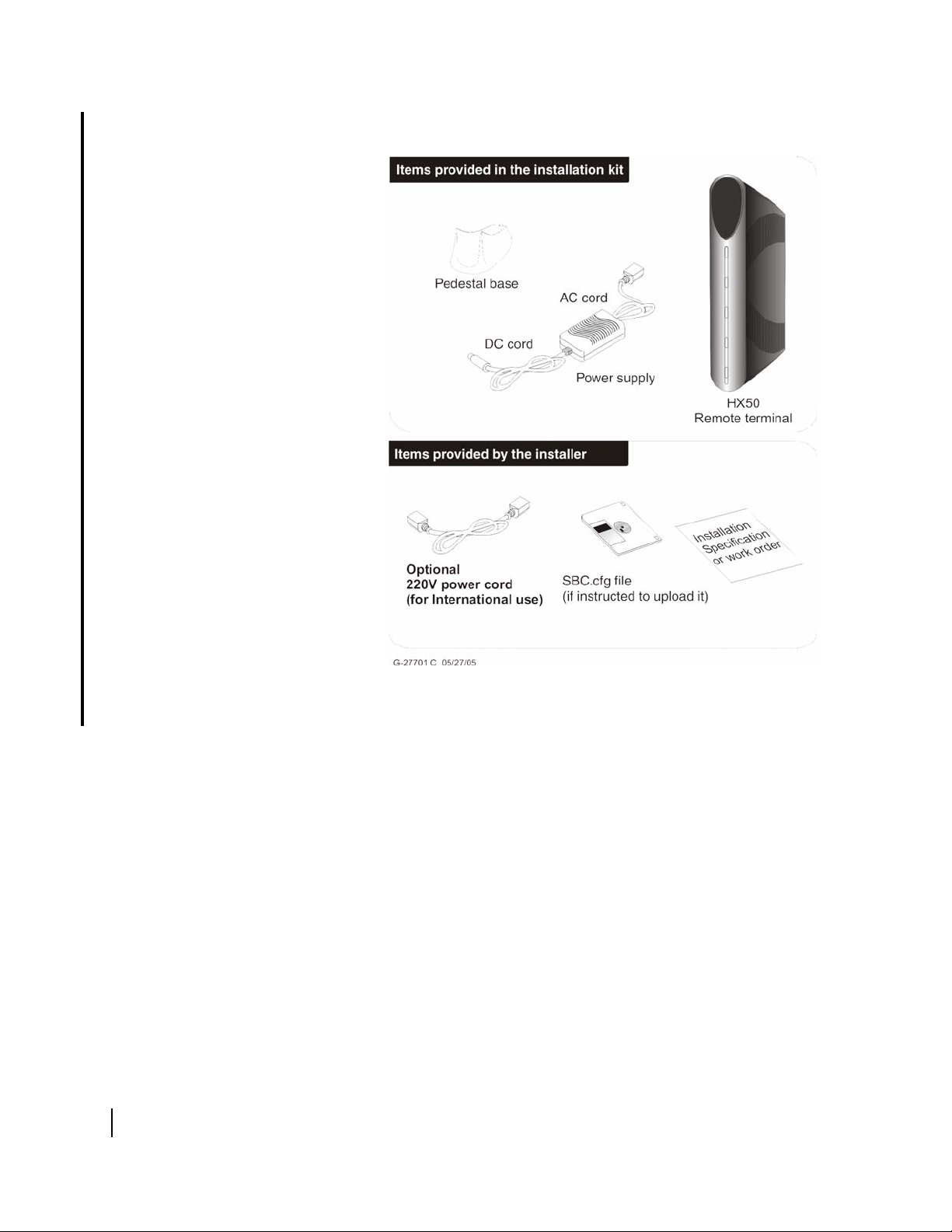
Figure 8 shows the items in the HX50 installation kit.
12
Chapter 2 • Preparing for the Installation
1037106-0001 Revision B.03-Draft
Figure 8: HX50 installation kit components
 Loading...