

Hughes HX200 Installation Manual

HX System
Satellite Router Installation Guide
Model: HX200
Draft
1038054-0001
Revision A.04 - Inspection
Draft
October 27, 2008

Revision record
Revision Date of issue Scope
A.01 October 1, 2008 Preliminary review draft
A.02 October 13, 2008 Updated draft.
A.03 October 16, 2008 Agency Test draft
A.04 October 27, 2008 Inspection draft
Copyright © 2008 Hughes Network Systems, LLC
All rights reserved. This publication and its contents are proprietary to Hughes Network Systems,
LLC. No part of this publication may be reproduced in any form or by any means without the written
permission of Hughes Network Systems, LLC, 11717 Exploration Lane, Germantown, Maryland
20876.
Hughes Network Systems, LLC has made every effort to ensure the correctness and completeness
of the material in this document. Hughes Network Systems, LLC shall not be liable for errors
contained herein. The information in this document is subject to change without notice. Hughes
Network Systems, LLC makes no warranty of any kind with regard to this material, including, but not
limited to, the implied warranties of merchantability and fitness for a particular purpose.
Trademarks
Hughes, Hughes Network Systems, and HughesNet are trademarks of Hughes Network Systems,
LLC. All other trademarks are the property of their respective owners.

Understanding safety alert messages
Safety alert messages call attention to potential safety hazards
and tell you how to avoid them. These messages are identified by
the signal words DANGER, WARNING, CAUTION, or
NOTICE, as illustrated below. To avoid possible property
damage, personal injury, or in some cases possible death, read
and comply with all safety alert messages.
Messages concerning personal injury
The signal words DANGER, WARNING, and CAUTION
indicate hazards that could result in personal injury or in some
cases death, as explained below. Each of these signal words
indicates the severity of the potential hazard.
DANGER
DANGER indicates a potentially hazardous situation which, if not
avoided, will result in death or serious injury.
WARNING
WARNING indicates a potentially hazardous situation which, if
not avoided, could result in death or serious injury.
CAUTION
CAUTION indicates a potentially hazardous situation which, if
not avoided, could result in minor or moderate injury.
Messages concerning property damage
A NOTICE concerns property damage only.
NOTICE
NOTICE is used for advisory messages concerning possible
property damage, product damage or malfunction, data loss, or
other unwanted results—but not personal injury.
• Understanding safety alert messages
1038054-0001 Revision A.04 - Inspection Draft
iii

Safety symbols
The generic safety alert symbol
calls attention to a potential personal injury hazard. It appears
next to the DANGER, WARNING, and CAUTION signal words
as part of the signal word label. Other symbols may appear next
to DANGER, WARNING, or CAUTION to indicate a specific
type of hazard (for example, fire or electric shock). If other
hazard symbols are used in this document they are identified in
this section.
• Understanding safety alert messages
iv
1038054-0001 Revision A.04 - Inspection Draft

Contents
Understanding safety alert messages . . . . . . . . . . . . . . . iii
Messages concerning personal injury. . . . . . . . . . . . . . . . . . . . . iii
Messages concerning property damage . . . . . . . . . . . . . . . . . . . iii
Safety symbols . . . . . . . . . . . . . . . . . . . . . . . . . . . . . . . . . . . . . . iv
Chapter 1
Introduction . . . . . . . . . . . . . . . . . . . . . . . . . . . . . . . . . . . .1
Scope . . . . . . . . . . . . . . . . . . . . . . . . . . . . . . . . . . . . . . . . . . . . . .1
Audience. . . . . . . . . . . . . . . . . . . . . . . . . . . . . . . . . . . . . . . . . .1
Related publications . . . . . . . . . . . . . . . . . . . . . . . . . . . . . . . . . . .1
HX200 satellite router overview . . . . . . . . . . . . . . . . . . . . . . . . .2
HX200 rack mount kit . . . . . . . . . . . . . . . . . . . . . . . . . . . . . . . . .3
HX200 features. . . . . . . . . . . . . . . . . . . . . . . . . . . . . . . . . . . . . . .3
Transmission types . . . . . . . . . . . . . . . . . . . . . . . . . . . . . . . . . .4
Linear Ku-band. . . . . . . . . . . . . . . . . . . . . . . . . . . . . . . . . . .4
Linear C-band. . . . . . . . . . . . . . . . . . . . . . . . . . . . . . . . . . . .4
Saturated Ku-band . . . . . . . . . . . . . . . . . . . . . . . . . . . . . . . .4
Saturated C-band . . . . . . . . . . . . . . . . . . . . . . . . . . . . . . . . .4
DVB-S2 compliant outroute. . . . . . . . . . . . . . . . . . . . . . . . . . .4
Mobility . . . . . . . . . . . . . . . . . . . . . . . . . . . . . . . . . . . . . . . . . .5
Signal and data interfaces. . . . . . . . . . . . . . . . . . . . . . . . . . . . .5
Mechanical . . . . . . . . . . . . . . . . . . . . . . . . . . . . . . . . . . . . . . . .5
Satellite router specifications . . . . . . . . . . . . . . . . . . . . . . . . . . . .5
Installation and commissioning . . . . . . . . . . . . . . . . . . . . . . . . . .6
Contact information . . . . . . . . . . . . . . . . . . . . . . . . . . . . . . . . . . .7
Chapter 2
Assembling and connecting HX200 hardware . . . . . . . .9
Preparing for the installation . . . . . . . . . . . . . . . . . . . . . . . . . . . .9
Items required for installation . . . . . . . . . . . . . . . . . . . . . . . . .9
Confirming installer laptop and site requirements . . . . . . . . .10
Installer laptop requirements . . . . . . . . . . . . . . . . . . . . . . .10
Remote site requirements . . . . . . . . . . . . . . . . . . . . . . . . . .10
Conducting the site survey . . . . . . . . . . . . . . . . . . . . . . . . . . .11
Connecting the receive and transmit cables . . . . . . . . . . . . . . . .11
Connecting the Ethernet and power cables . . . . . . . . . . . . . . . .12
Powering up and observing the LEDs . . . . . . . . . . . . . . . . . . . .13
• Contents
1038054-0001 Revision A.04 - Inspection Draft
v

Chapter 3
Commissioning the HX200 satellite router . . . . . . . . . .15
Manual commissioning . . . . . . . . . . . . . . . . . . . . . . . . . . . . . . .15
Entering manual commissioning parameters . . . . . . . . . . . . .15
Spreading . . . . . . . . . . . . . . . . . . . . . . . . . . . . . . . . . . . . . .17
Spreading disabled . . . . . . . . . . . . . . . . . . . . . . . . . . . . .18
Spreading enabled. . . . . . . . . . . . . . . . . . . . . . . . . . . . . .18
NOC override . . . . . . . . . . . . . . . . . . . . . . . . . . . . . . . . .20
Antenna pointing . . . . . . . . . . . . . . . . . . . . . . . . . . . . . . . . . .20
Satellite-based commissioning . . . . . . . . . . . . . . . . . . . . . . . . . .23
Obtaining an IP address from the HX200 satellite router . . .23
Uploading the SBC configuration file to the HX200 . . . . . . . 25
Commissioning the HX200 . . . . . . . . . . . . . . . . . . . . . . . . . .27
Chapter 4
Completing the installation . . . . . . . . . . . . . . . . . . . . . . .37
Confirming that all files are current . . . . . . . . . . . . . . . . . . . . . .37
Connecting the HX200 satellite router to a computer . . . . . . . .38
Unable to access enterprise resources . . . . . . . . . . . . . . . . . .38
Printing the System Information page . . . . . . . . . . . . . . . . . . . .39
Creating a shortcut to the System Control Center . . . . . . . . . . .40
Chapter 5
The System Control Center . . . . . . . . . . . . . . . . . . . . . .43
Accessing the System Control Center . . . . . . . . . . . . . . . . . . . .43
System Control Center Home page . . . . . . . . . . . . . . . . . . . . . .45
System indicators . . . . . . . . . . . . . . . . . . . . . . . . . . . . . . . . . .45
Links . . . . . . . . . . . . . . . . . . . . . . . . . . . . . . . . . . . . . . . . . . . .46
System Status . . . . . . . . . . . . . . . . . . . . . . . . . . . . . . . . . . .46
Diagnostic Utilities. . . . . . . . . . . . . . . . . . . . . . . . . . . . . . .46
Help . . . . . . . . . . . . . . . . . . . . . . . . . . . . . . . . . . . . . . . . . .46
System Status page. . . . . . . . . . . . . . . . . . . . . . . . . . . . . . . . . . .47
Reception Information page . . . . . . . . . . . . . . . . . . . . . . . . . . . .48
Receive status messages . . . . . . . . . . . . . . . . . . . . . . . . . . . . .49
Transmission Information page . . . . . . . . . . . . . . . . . . . . . . . . .52
Transmit status messages . . . . . . . . . . . . . . . . . . . . . . . . . . . .53
System Information page . . . . . . . . . . . . . . . . . . . . . . . . . . . . . .58
Connectivity Test page. . . . . . . . . . . . . . . . . . . . . . . . . . . . . . . .60
Optional Features Pages . . . . . . . . . . . . . . . . . . . . . . . . . . . . . . .61
Firewall Configuration page. . . . . . . . . . . . . . . . . . . . . . . . . .61
Understanding how the firewall works. . . . . . . . . . . . . . . .62
Firewall rule restrictions. . . . . . . . . . . . . . . . . . . . . . . . .62
• Contents
vi
1038054-0001 Revision A.04 - Inspection Draft

Creating firewall rules . . . . . . . . . . . . . . . . . . . . . . . . . . . .62
Modifying and deleting firewall rules . . . . . . . . . . . . . . . .64
Enabling and disabling the firewall . . . . . . . . . . . . . . . . . .65
The Firewall Statistics page . . . . . . . . . . . . . . . . . . . . . . . . . .65
Viewing firewall statistics . . . . . . . . . . . . . . . . . . . . . . . . .66
Resetting firewall statistics counters . . . . . . . . . . . . . . . . .66
Port Forwarding Configuration page . . . . . . . . . . . . . . . . . . .67
Understanding port forwarding . . . . . . . . . . . . . . . . . . . . .67
Port forwarding rule restrictions. . . . . . . . . . . . . . . . . . .68
Creating port forwarding rules . . . . . . . . . . . . . . . . . . . . . .68
Modifying and deleting port forwarding rules . . . . . . . . . .69
Help page . . . . . . . . . . . . . . . . . . . . . . . . . . . . . . . . . . . . . . . . . .70
Advanced pages . . . . . . . . . . . . . . . . . . . . . . . . . . . . . . . . . . . . .71
Chapter 6
Troubleshooting . . . . . . . . . . . . . . . . . . . . . . . . . . . . . . . .73
HX200 LEDs . . . . . . . . . . . . . . . . . . . . . . . . . . . . . . . . . . . . . . .73
LED appearances during normal operation . . . . . . . . . . . . . .74
Connectivity problems . . . . . . . . . . . . . . . . . . . . . . . . . . . . . . . .78
Cannot access the System Control Center . . . . . . . . . . . . . . . . . 78
Computer is connected directly to the satellite router . . . . . . 78
Satellite router is connected to an Ethernet device. . . . . . . . .79
Cannot access network resources . . . . . . . . . . . . . . . . . . . . . . . .79
Accessing the System Control Center . . . . . . . . . . . . . . . . . .80
Confirming that the satellite router is commissioned. . . . . . .80
Checking the receive signal . . . . . . . . . . . . . . . . . . . . . . . . . .80
Weather and signal strength . . . . . . . . . . . . . . . . . . . . . . . .80
Checking the transmit signal . . . . . . . . . . . . . . . . . . . . . . . . .80
Checking that TCP Acceleration is operational . . . . . . . . . . .81
Checking that Web Acceleration is operational . . . . . . . . . . .81
Checking system gateway connectivity . . . . . . . . . . . . . . . . .82
Checking enterprise network connectivity . . . . . . . . . . . . . . .83
Checking DNS settings. . . . . . . . . . . . . . . . . . . . . . . . . . . .84
Checking for viruses. . . . . . . . . . . . . . . . . . . . . . . . . . . . . . . .85
No browsing issues. . . . . . . . . . . . . . . . . . . . . . . . . . . . . . . . . . .85
Hot cable connector . . . . . . . . . . . . . . . . . . . . . . . . . . . . . . . . . .85
Slow transmission speed or intermittent operation . . . . . . . . . .86
Appendix A
Configuring a Windows computer to support DHCP .87
Windows XP. . . . . . . . . . . . . . . . . . . . . . . . . . . . . . . . . . . . . . . .87
Windows 2000 . . . . . . . . . . . . . . . . . . . . . . . . . . . . . . . . . . . . . .90
Windows 98SE and Me . . . . . . . . . . . . . . . . . . . . . . . . . . . . . . .93
• Contents
1038054-0001 Revision A.04 - Inspection Draft
vii

Appendix B
DVB-S2 compliant outroute . . . . . . . . . . . . . . . . . . . . . .97
DVB-S2 compliant outroute. . . . . . . . . . . . . . . . . . . . . . . . . . . .97
QEF performance . . . . . . . . . . . . . . . . . . . . . . . . . . . . . . . . . . . .97
Appendix C
Updating the satellite router software . . . . . . . . . . . . .101
Saving the utility on the installer laptop. . . . . . . . . . . . . . . . . .101
Configuring the TCP/IP properties on the installer laptop. . . .102
Windows XP. . . . . . . . . . . . . . . . . . . . . . . . . . . . . . . . . . . . .102
Windows 2000 . . . . . . . . . . . . . . . . . . . . . . . . . . . . . . . . . . .105
Windows 98 SE and Me . . . . . . . . . . . . . . . . . . . . . . . . . . . .107
Updating the fallback.bin file. . . . . . . . . . . . . . . . . . . . . . . . . .109
Troubleshooting the update . . . . . . . . . . . . . . . . . . . . . . . . . . .110
Appendix D
Disabling a Web browser proxy connection . . . . . . . .111
Internet Explorer. . . . . . . . . . . . . . . . . . . . . . . . . . . . . . . . . . . .111
Netscape . . . . . . . . . . . . . . . . . . . . . . . . . . . . . . . . . . . . . . . . . .112
Appendix E
HX200 transmitter and receiver specifications. . . . . .115
Appendix F
Conforming with standards and directives . . . . . . . . .117
TIA IPoS standard . . . . . . . . . . . . . . . . . . . . . . . . . . . . . . . . . .117
Certifications and cautions . . . . . . . . . . . . . . . . . . . . . . . . . . . .117
Safety-operating conditions for Canada . . . . . . . . . . . . . . . .118
Repairs in Canada. . . . . . . . . . . . . . . . . . . . . . . . . . . . . . .118
Safety, emission, and immunity standards . . . . . . . . . . . . . .118
Canada Class B warning. . . . . . . . . . . . . . . . . . . . . . . . . .119
FCC part 15 notice . . . . . . . . . . . . . . . . . . . . . . . . . . . . . .119
R&TTE notice . . . . . . . . . . . . . . . . . . . . . . . . . . . . . . . . .120
Material compliance . . . . . . . . . . . . . . . . . . . . . . . . . . . . . . . . .120
RoHS compliance. . . . . . . . . . . . . . . . . . . . . . . . . . . . . . . . .120
RoHs compliance with exemptions . . . . . . . . . . . . . . . . . . .120
Acronyms and abbreviations . . . . . . . . . . . . . . . . . . . .123
Index . . . . . . . . . . . . . . . . . . . . . . . . . . . . . . . . . . . . . . . .125
viii
• Contents
1038054-0001 Revision A.04 - Inspection Draft

Figures
Chapter 1
1. HX200 satellite router (front and back) . . . . . . . . . . . . . . . . . . . . . . . . . . . . . . . .3
Chapter 2
2. HX200 installation kit components . . . . . . . . . . . . . . . . . . . . . . . . . . . . . . . . . . .9
3. Connecting the receive and transmit cables to the satellite router . . . . . . . . . . .11
Chapter 3
4. HX200 Broadband Satellite Setup screen . . . . . . . . . . . . . . . . . . . . . . . . . . . . .16
5. HX200 Manual Commission screen. . . . . . . . . . . . . . . . . . . . . . . . . . . . . . . . . .17
6. Sample of allowed inroute symbol rates with spreading disabled . . . . . . . . . . .18
7. Sample of allowed inroute symbol rates with spreading enabled . . . . . . . . . . .19
8. Antenna pointing screen . . . . . . . . . . . . . . . . . . . . . . . . . . . . . . . . . . . . . . . . . . .21
9. Receive pointing . . . . . . . . . . . . . . . . . . . . . . . . . . . . . . . . . . . . . . . . . . . . . . . . .22
10. Successful ping . . . . . . . . . . . . . . . . . . . . . . . . . . . . . . . . . . . . . . . . . . . . . . . . . .24
11. Failed ping . . . . . . . . . . . . . . . . . . . . . . . . . . . . . . . . . . . . . . . . . . . . . . . . . . . . .24
12. HX200 Broadband Satellite Setup screen . . . . . . . . . . . . . . . . . . . . . . . . . . . . .26
13. Antenna Location screen . . . . . . . . . . . . . . . . . . . . . . . . . . . . . . . . . . . . . . . . . .27
14. Entering location manually. . . . . . . . . . . . . . . . . . . . . . . . . . . . . . . . . . . . . . . . .28
15. Selecting the satellite and transponder . . . . . . . . . . . . . . . . . . . . . . . . . . . . . . . .29
16. Entering satellite parameters manually. . . . . . . . . . . . . . . . . . . . . . . . . . . . . . . .30
17. Verifying satellite parameters. . . . . . . . . . . . . . . . . . . . . . . . . . . . . . . . . . . . . . .31
18. Selecting the transmit radio . . . . . . . . . . . . . . . . . . . . . . . . . . . . . . . . . . . . . . . .32
19. Receive pointing . . . . . . . . . . . . . . . . . . . . . . . . . . . . . . . . . . . . . . . . . . . . . . . . .33
20. Accessing the registration server . . . . . . . . . . . . . . . . . . . . . . . . . . . . . . . . . . . .34
21. Accepting the security certificate . . . . . . . . . . . . . . . . . . . . . . . . . . . . . . . . . . . .34
22. Registering a satellite router (enterprise user) – entering site ID . . . . . . . . . . . .35
Chapter 4
23. Final configuration . . . . . . . . . . . . . . . . . . . . . . . . . . . . . . . . . . . . . . . . . . . . . . .38
24. Creating a shortcut to the System Control Center . . . . . . . . . . . . . . . . . . . . . . .40
25. Entering the System Control Center URL in the Create Shortcut window . . . .40
26. Entering the name of the shortcut. . . . . . . . . . . . . . . . . . . . . . . . . . . . . . . . . . . .41
Chapter 5
27. System Control Center home page . . . . . . . . . . . . . . . . . . . . . . . . . . . . . . . . . . .44
28. System indicators . . . . . . . . . . . . . . . . . . . . . . . . . . . . . . . . . . . . . . . . . . . . . . . .45
• Figures
1038054-0001 Revision A.04 - Inspection Draft
ix

29. System Status indicator reporting a problem . . . . . . . . . . . . . . . . . . . . . . . . . . .45
30. System Status page . . . . . . . . . . . . . . . . . . . . . . . . . . . . . . . . . . . . . . . . . . . . . . .47
31. Reception Information page . . . . . . . . . . . . . . . . . . . . . . . . . . . . . . . . . . . . . . . .48
32. Transmission Information page . . . . . . . . . . . . . . . . . . . . . . . . . . . . . . . . . . . . .52
33. System Information page . . . . . . . . . . . . . . . . . . . . . . . . . . . . . . . . . . . . . . . . . .58
34. Connectivity Test page . . . . . . . . . . . . . . . . . . . . . . . . . . . . . . . . . . . . . . . . . . . .60
35. Successful connectivity test . . . . . . . . . . . . . . . . . . . . . . . . . . . . . . . . . . . . . . . .60
36. Firewall configuration page . . . . . . . . . . . . . . . . . . . . . . . . . . . . . . . . . . . . . . . .61
37. Create firewall rule page. . . . . . . . . . . . . . . . . . . . . . . . . . . . . . . . . . . . . . . . . . .63
38. Modify/delete firewall rule page . . . . . . . . . . . . . . . . . . . . . . . . . . . . . . . . . . . .64
39. Firewall Statistics page. . . . . . . . . . . . . . . . . . . . . . . . . . . . . . . . . . . . . . . . . . . .66
40. Port Forwarding Configuration page . . . . . . . . . . . . . . . . . . . . . . . . . . . . . . . . .67
41. Create port forwarding rule page . . . . . . . . . . . . . . . . . . . . . . . . . . . . . . . . . . . .68
42. Modify/delete port forwarding rule page . . . . . . . . . . . . . . . . . . . . . . . . . . . . . .69
43. Help page . . . . . . . . . . . . . . . . . . . . . . . . . . . . . . . . . . . . . . . . . . . . . . . . . . . . . .70
44. Advanced page . . . . . . . . . . . . . . . . . . . . . . . . . . . . . . . . . . . . . . . . . . . . . . . . . .71
Chapter 6
45. Satellite router LEDs . . . . . . . . . . . . . . . . . . . . . . . . . . . . . . . . . . . . . . . . . . . . .73
Appendix A
46. Network Connections - Windows XP . . . . . . . . . . . . . . . . . . . . . . . . . . . . . . . .88
47. Local Area Connection Properties - Windows XP. . . . . . . . . . . . . . . . . . . . . . .89
48. Internet Protocol Properties - Windows XP . . . . . . . . . . . . . . . . . . . . . . . . . . . .89
49. Network and Dialup Connections - Windows 2000. . . . . . . . . . . . . . . . . . . . . .90
50. Local Area Connection Properties - Windows 2000 . . . . . . . . . . . . . . . . . . . . .91
51. Internet Protocol Properties - Windows 2000 . . . . . . . . . . . . . . . . . . . . . . . . . .92
52. Control Panel - Windows 98SE and Me. . . . . . . . . . . . . . . . . . . . . . . . . . . . . . .93
53. Network window - Windows 98SE and Me. . . . . . . . . . . . . . . . . . . . . . . . . . . .94
54. TCP/IP Properties - Windows 98SE and Me . . . . . . . . . . . . . . . . . . . . . . . . . . .94
55. Gateway tab - Windows 98SE and Me. . . . . . . . . . . . . . . . . . . . . . . . . . . . . . . .95
Appendix C
56. Saving the Fallback Updater utility . . . . . . . . . . . . . . . . . . . . . . . . . . . . . . . . .102
57. Network Connections - Windows XP . . . . . . . . . . . . . . . . . . . . . . . . . . . . . . .103
58. Local Area Connection Properties - Windows XP. . . . . . . . . . . . . . . . . . . . . .104
59. Internet Protocol Properties - Windows XP . . . . . . . . . . . . . . . . . . . . . . . . . . .104
60. Network and Dial-up Connections - Windows 2000 . . . . . . . . . . . . . . . . . . . .105
61. Local Area Connection Properties - Windows 2000 . . . . . . . . . . . . . . . . . . . .106
62. Internet Protocol Properties - Windows 2000 . . . . . . . . . . . . . . . . . . . . . . . . .106
63. Control Panel - Windows 98SE and Me. . . . . . . . . . . . . . . . . . . . . . . . . . . . . .107
64. Network window - Windows 98SE and Me. . . . . . . . . . . . . . . . . . . . . . . . . . .108
• Figures
x
1038054-0001 Revision A.04 - Inspection Draft

65. TCP/IP Properties - Windows 98SE and Me . . . . . . . . . . . . . . . . . . . . . . . . . .108
66. Entering the satellite router IP address . . . . . . . . . . . . . . . . . . . . . . . . . . . . . . .109
Appendix D
67. Selecting the Connections tab - IE . . . . . . . . . . . . . . . . . . . . . . . . . . . . . . . . . .111
68. Accessing LAN settings - IE . . . . . . . . . . . . . . . . . . . . . . . . . . . . . . . . . . . . . .112
69. Accessing proxy settings - Netscape . . . . . . . . . . . . . . . . . . . . . . . . . . . . . . . .112
Appendix F
70. IPoS symbol . . . . . . . . . . . . . . . . . . . . . . . . . . . . . . . . . . . . . . . . . . . . . . . . . . .117
• Figures
1038054-0001 Revision A.04 - Inspection Draft
xi

xii
• Figures
1038054-0001 Revision A.04 - Inspection Draft

Tables
Chapter 1
1. Linear L-band radios . . . . . . . . . . . . . . . . . . . . . . . . . . . . . . . . . . . . . . . . . . . . . .4
2. Linear C-band radio . . . . . . . . . . . . . . . . . . . . . . . . . . . . . . . . . . . . . . . . . . . . . . .4
3. Saturated Ku-band radios . . . . . . . . . . . . . . . . . . . . . . . . . . . . . . . . . . . . . . . . . . .4
4. Saturated C-band radios . . . . . . . . . . . . . . . . . . . . . . . . . . . . . . . . . . . . . . . . . . . .4
5. HX200 satellite router specifications . . . . . . . . . . . . . . . . . . . . . . . . . . . . . . . . . .5
Chapter 5
6. Receive code (RxCode) messages and corrective actions . . . . . . . . . . . . . . . . . 50
7. Transmit code (TxCode) messages and corrective actions . . . . . . . . . . . . . . . .53
8. Firewall rule configuration fields . . . . . . . . . . . . . . . . . . . . . . . . . . . . . . . . . . . .63
Chapter 6
9. Satellite router front panel LED operation . . . . . . . . . . . . . . . . . . . . . . . . . . . . .75
Appendix B
10. Outroutes . . . . . . . . . . . . . . . . . . . . . . . . . . . . . . . . . . . . . . . . . . . . . . . . . . . . . .97
11. Ratio Between Energy per Information Bit and Single Sided Noise Power Spectral
Density . . . . . . . . . . . . . . . . . . . . . . . . . . . . . . . . . . . . . . . . . . . . . . . . . . . . . . . .98
Appendix E
12. HX200 Transmitter Specifications . . . . . . . . . . . . . . . . . . . . . . . . . . . . . . . . . .115
13. HX200 Receiver Specifications . . . . . . . . . . . . . . . . . . . . . . . . . . . . . . . . . . . .115
Appendix F
14. System safety, emission, and immunity standards compliance . . . . . . . . . . . .119
15. Maximum acceptable RoHS concentration . . . . . . . . . . . . . . . . . . . . . . . . . . .120
• Tables
1038054-0001 Revision A.04 - Inspection Draft
xiii

xiv
• Tables
1038054-0001 Revision A.04 - Inspection Draft

Introduction
This chapter discusses the following topics:
• Scope on page 1
• Related publications on page 1
• HX200 satellite router overview on page 2
• HX200 rack mount kit on page 3
• HX200 features on page 3
• Satellite router specifications on page 5
• Installation and commissioning on page 6
• Contact information on page 7
Chapter 1
Scope
Audience
Related publications
This manual explains how to install, commission, and service the
Hughes HX200 satellite router.
This manual is intended for use by the following audiences:
• Professional installers
• Installer trainers, who prepare separate instructions for the
installers
• Call center operators, who respond to customers’ calls
• Call center trainers, who train call center operators
The following documents provide more detailed information
about HX system and gateway components.
• Guide to Gateway Customer Documentation
(1037851-0001)
• Gateway Installation Manual, Volume 1: Overview and
Hardware Installation (1037853-0001)
• Gateway Installation Manual, Volume 2: Component
Configuration (1037854-0001)
• Gateway Operations and Troubleshooting Manual, Volume
1: Satellite Router Operations (1037855-0001)
• Gateway Operations and Troubleshooting Manual, Volume
2: Gateway Operations (1037856-0001)
• Gateway Reference Manual, Volume 1: Vision Interface
(1037857-0001)
Chapter 1 • Introduction
1038054-0001 Revision A.04 - Inspection Draft
1

• Gateway Reference Manual, Volume 2: NOC Forms and
Local Interfaces (1037858-0001)
• Remote Terminal Installation Guide, Models: HX50,
HX100 (1037106-0001)
• Remote Terminal User Guide, Models: HX50, HX100
(1036942-0001)
• Remote Terminal User Guide, Model HX150
(1037194-0001)
• Remote Terminal Installation Guide, Model HX150,
(1037125-0001)
• Satellite Router User Guide, Model HX200 (1038055-0001)
HX200 satellite router overview
The HX200, as shown in Figure 1 on page 3, is a
high-performance satellite router designed to support
high-bandwidth links with mesh/star capability and QoS features
such as Min/Max CIR together with dynamic alllocation of
bandwidth. With integrated IP features including RIPv1, RIPv2,
BGP, DHCP, NAT/PAT, and DNS Server/Relay functionality,
together with a high-performance satellite modem, the HX200 is
a full-featured IP router. The HX200 enables superior IP
connectivity for a variety of applications including cellular
backhaul, MPLS extension services, virtual leased line, mobile
services and other high-bandwidth solutions.
The HX200 satellite router provides two 10/100 LAN ports with
one being used for local LAN connectivity and one being used for
WAN connectivity. The Ethernet LAN port can be connected via
a straight-through or crossover Cat-5 cable to a single computer
or to an Ethernet hub/switch port.
It is completely self-contained requiring no external PC to host
any functions or software. The software is automatically updated
from the Network Operations Center (NOC).
Chapter 1 • Introduction
2
1038054-0001 Revision A.04 - Inspection Draft
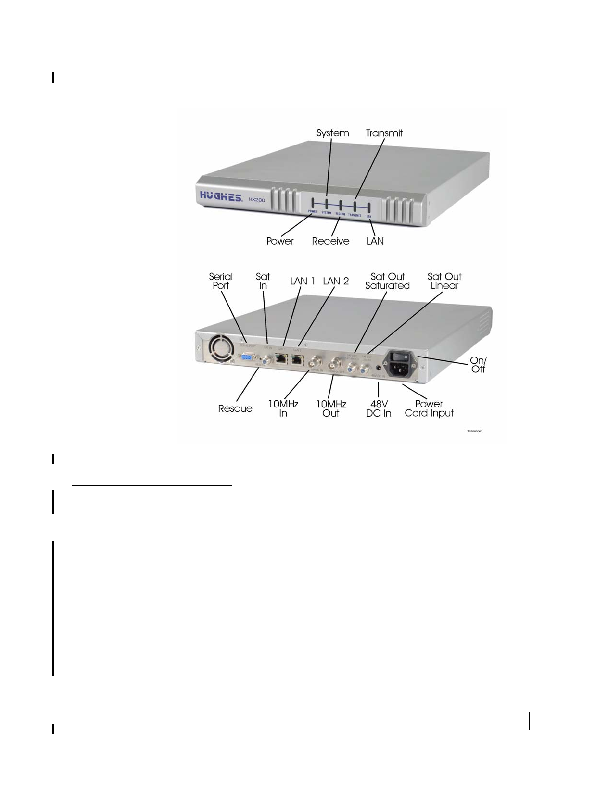
Figure 1: HX200 satellite router (front and back)
HX200 rack mount kit
HX200 features
The HX200 equipment rack consists of an industry standard 1U
rack-mountable enclosure.
Low cost self-hosted device HX terminal with 400MHz MIPS
processor
• Transmission types:
– Linear Ku-band
– Linear C-band
– Saturated Ku-band
– Saturated C-band
• DVB-S2 compliant outroute
• Mobility
Chapter 1 • Introduction
1038054-0001 Revision A.04 - Inspection Draft
3

The HX200 satellite router provides support for HX150
capabilities including:
• L-band transmitter
• Support for GPS
• Inroute spreading
– 256 Ksps X 2
– 256 Ksps X 4
– 512 Ksps X 2
Transmission types
Linear Ku-band
Linear C-band
Saturated Ku-band
The HX200 supports both saturated and linear transmit outdoor
units (ODUs).
Table 1: Linear L-band radios
Radio Part Number
4W Linear BUC 9502667-0002
4W Linear
BUC/Tria/LNB
Table 2: Linear C-band radio
Radio Part Number
5W Linear BUC 9502666-0001
Table 3: Saturated Ku-band radios
Radio Part Number
1W Anubis/LNB/Tria 1500172-0101
2W Anubis/LNB/Tria 1500172-0102
Saturated C-band
DVB-S2 compliant outroute
Chapter 1 • Introduction
4
1038054-0001 Revision A.04 - Inspection Draft
Table 4: Saturated C-band radios
Component Part Number
2W Tigris (India-C) 1028050-0006
2W MTI (Extended-C) 1034468-0002
The HX200 receives a single Digital Video Braodcast - second
generation (DVB-S2) compliant outroute. For detailed

information on the compliant outroute and ratios, please see
Table 10 on page 97 and Table 11 on page 98.
The HX200 supports outroute symbol rates less than 1Msps.
Mobility
Signal and data interfaces
Mechanical
The HX200 provides doppler compensation for radial speeds up
to 150 mph.
The following signal and data interfaces are supported:
• Dual 10/100 Ethernet LAN ports with Auto-MDIX support,
configurable as a two-port switch or as two independent LAN
segments
• EIA-232 receive and transmit ports for control signaling in
Maritime applications
• EIA-232 receive and transmit ports for communication to a
GPS terminal
• EIA-232 debug port (stuffing option)
• 10MHz reference circuitry allows simultaneous receive and
transmit of 10MHz reference to/from the rear panel
– 10MHz reference clock output
– 10MHz reference clock input
• 100 to 253V AC input through detachable power cord
• 48V power supply DC voltage input port for supporting >
5W radios
The HX200 includes an industry standard 1U rack-mountable
enclosure.
Satellite router
Table 5 lists the specifications for the HX200 satellite router.
specifications
Table 5: HX200 satellite router specifications
Product element Specification
Physical Interfaces
Two 10/100 BaseT Ethernet LAN RJ45 ports (independent subnets)
One Serial Port (RS-422 or RS-232)
Satellite Specifications
Outbound Channel DVB-S2 with Adaptive Coding and Modulation
Outbound Rate 1-45 Msps (in 0.5 Msps steps)
Outbound Modulation QPSK, 8PSK (Adaptive Modulation)
Outbound Coding BCH with LDPC 3/5, 1/2, 2/3, 3/4, 5/6, 8/9, 9/10 (Adaptive Coding)
Inbound Channel IPoS (FDMA/TDMA)
Chapter 1 • Introduction
1038054-0001 Revision A.04 - Inspection Draft
5

Table 5: HX200 satellite router specifications (Continued)
Product element Specification
Inbound Channel Rate 256, 512, 1024, 2048 ksps
Inbound Channel
Modulation
Inbound Channel
Coding
Bit Error Rate (Receive)
Bit Error Rate
(Transmit)
Interface to ODU Industry standard BUC (L-Band) or Hughes saturated carrier BUC
Mechanical and Environmental
Weight 2.4 lb (1.089 kg)
Width 1.7 inch (4.32 cm)
Height 9.5 inch (24.13 cm)
Depth 10.5 inch (26.67 cm)
Safe operating
temperature range
Safe operating humidity
range
Safe altitude 10,000 ft
Cooling method Convection
Main processor 300 MHz
Main memory 64 Mbyte
Flash memory 16 Mbyte
Protocol support TCP/IP (Transmission Control Protocol / Internet Protocol) protocol suite
Interfaces/ports Two Ethernet ports supporting 10BaseT or 100BaseT operation, RJ45-switched
OQPSK
Rate 1/2, 2/3, 4/5 with TurboCode (Adaptive Coding)
-10
10
or better
10-7 or better
4.5 inch (11.43 cm) with pedestal base
9.75 inch (24.77 cm) with pedestal base
5 to 40°C (Above 5000 ft altitude, reduce maximum temperature by 1°C per
1000 ft)
5% to 95% non-condensing
Telephone line port
Installation and commissioning
Chapter 1 • Introduction
6
1038054-0001 Revision A.04 - Inspection Draft
The installation and commissioning of the HX200 satellite router
is a multi-step process involving two pieces of equipment—the
HX200 satellite router and the associated transport device. The
workflow and chapter reference numbers for the process steps
follow.
1. Preparing the satellite router for installation
Chapter 2 on page 9
2. Assembling the HX200 satellite router
Chapter 2 on page 9
3. Commissioning the HX200 satellite router
Chapter 3 on page 15

4. Connecting the satellite router a computer
Chapter 4 on page 37
Commissioning is the process of registering an HX200 satellite
router for service. During the commissioning process you may
use auto selection or manual entry of parameters.
• Auto Selection - Allows you to choose the Network Access
Provider (NAP) from a predetermined list of providers. Many
of the commissioning parameters are automatically
configured for the provider chosen.
• Manual Entry - This mode requires you to enter all
parameters manually.
Contact information
If you experience installation problems with the HX200 satellite
router, first try the
For warranty or repair support, the contact information varies
depending on the location. If the customer needs service,
warranty or repair support, they should contact their customer
service representative in accordance with their service agreement.
Diagnostic Utilities on page 46.
Chapter 1 • Introduction
1038054-0001 Revision A.04 - Inspection Draft
7

Chapter 1 • Introduction
8
1038054-0001 Revision A.04 - Inspection Draft
Preparing for the installation
Chapter 2
Assembling and connecting
HX200 hardware
This chapter explains how to assemble and make the connections
to the HX200 satellite router. It covers the following topics:
• Preparing for the installation on page 9
• Connecting the receive and transmit cables on page 11
• Connecting the Ethernet and power cables on page 12
• Powering up and observing the LEDs on page 13
Items required for
installation
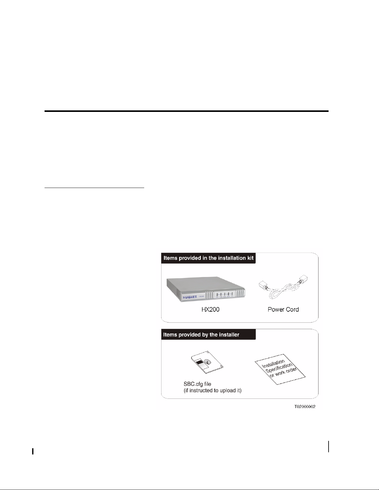
To install an HX200 satellite router, first ensure that you have all
the items shown in
HX200 installation kit.
Figure 2. These items are provided in the
Figure 2: HX200 installation kit components
Chapter 2 • Assembling and connecting HX200 hardware
1038054-0001 Revision A.04 - Inspection Draft
9

Confirming installer laptop
and site requirements
Before installing the HX200, you must confirm that the installer
laptop and the computer at the installation site meet specific
requirements.
Installer laptop requirements The installer laptop must meet the following requirements:
• Ethernet-enabled network interface card (NIC) and Ethernet
cable.
• Operating system with graphical user interface, such as
Windows, Linux with X Windows, or Mac OS X; and with
TCP/IP protocol support and client-side DHCP enabled. See
Appendix A – Configuring a Windows computer to support
DHCP, on page 87.
• Web browser such as Internet Explorer 5.5 or 6.0 or Netscape
with proxy settings disabled. See
Appendix D – Disabling a
Web browser proxy connection, on page 111.
• The latest version of the sbc.cfg file (if instructed to install
it).
Remote site requirements IP devices that will be connected to an HX200 satellite router
must implement the standard TCP/IP stack and provide an
Ethernet interface; otherwise there is no constraint to the
platforms and operating systems of devices attached to the
satellite routers.
For example, PCs, MACs, SPARC and Alpha workstations,
AS400 systems, and so on, can all be used on LANs connected to
an HX200 satellite router, running operating systems such as
Windows, Linux, Solaris, MAC OS X, AIX, VMS and others.
The following additional equipment is required:
• A power strip or surge protector. If neither of these devices
are available, proceed with the installation using a wall outlet
or other appropriate power source.
Note: Prior to beginning the installation, confirm that the
installer laptop is configured to support DHCP. See
Configuring a Windows computer to support DHCP for
instructions on configuring DHCP on a Windows computer.
Appendix A –
10
Chapter 2 • Assembling and connecting HX200 hardware
1038054-0001 Revision A.04 - Inspection Draft
CAUTION
• Do not block any ventilation openings. Do not install near
heat sources, such as radiators, heat registers, ovens,
stoves, or other apparatus (including amplifiers) that
produce heat.
• To ensure ventilation and prevent overheating, leave six
inches of space between the front and rear panels of the
satellite router assembly and any adjacent equipment or
structure. Ventilation is necessary to avoid overheating.
Conducting the site survey
Connecting the receive and transmit cables
Survey the installation site to confirm that it fulfills all the
requirements for using the HX system service. This includes
confirming that there is an unobstructed line-of-sight to the
appropriate satellite.
Additionally, review the installation specification or work order
for site-specific instructions.
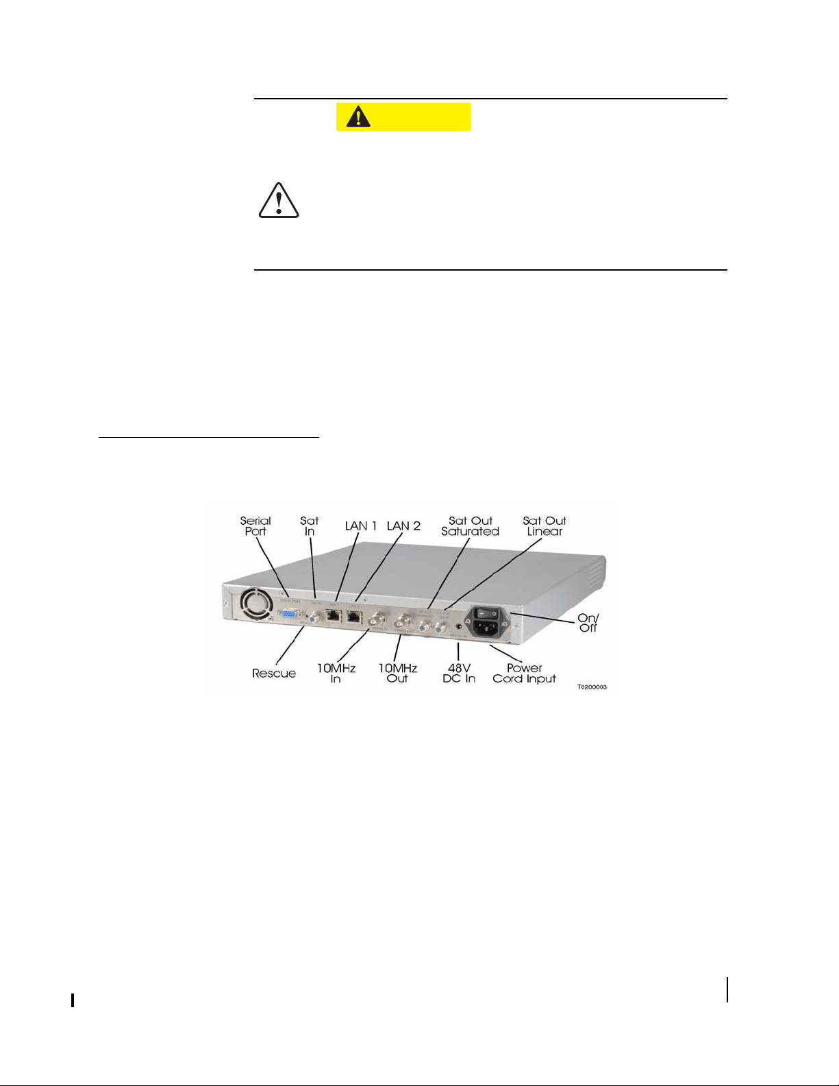
Connect the receive cable to the Satellite In connector on the
satellite router as shown in
Figure 3.
Figure 3: Connecting the receive and transmit cables to the satellite router
The HX200 offers two radio transmit options: saturated or linear.
The operator may select only one radio transmit option at any
time. There are potential ramifications to both software and
hardware if a cable is secured to the incorrect output connector or
if cables are connected to both outputs. For instance, a Linear
Radio transmit cable should not be connected to the Sat Out
Saturated connector on the back of the HX200 satellite router.
Chapter 2 • Assembling and connecting HX200 hardware
1038054-0001 Revision A.04 - Inspection Draft
11
From a software perspective, this selection takes place on the
Manual Commission screen (
Figure 5 on page 17).
CAUTION
Do not connect or disconnect a radio cable while the IDU is
powered on; this action may result in damage to the BUC.
CAUTION
Caution: The transmit and receive cable connectors must
be securely tightened.
• Make sure each connector is properly aligned
(not cross-threaded).
• Finger tight with no connector play is adequate.
Note: The satellite router may operate correctly when first
installed even if the transmit and receive cable connectors are not
adequately tightened. However, problems could develop later.
Therefore, correct operation of the satellite router is not an
indication that the cables are adequately tightened.
Connecting the Ethernet and power cables
Select a location for the satellite router that accommodates all
required cable connections, including the power source.
Using Figure 3 as a reference, connect the Ethernet cable:
1. Place the satellite router in the desired installation location.
CAUTION
• Do not block any ventilation openings. Do not place the
satellite router near heat sources such as radiators, heat
registers, ovens, stoves, or other apparatus (including
amplifiers) that produce heat.
• To ensure ventilation and prevent overheating, leave at
six inches of space between the front and rear panels of
the satellite router assembly and any adjacent equipment
or structure. Ventilation is necessary to avoid
overheating.
2. Connect the installer PC to the satellite router with an
Ethernet cable. Make sure no Ethernet routers or switches are
currently connected between the satellite router and the
installer PC.
12
Chapter 2 • Assembling and connecting HX200 hardware
1038054-0001 Revision A.04 - Inspection Draft

3. Connect the power cable.
Note: A surge protector is recommended.
Note: Do not connect any devices to the HX200 at this time.
Connect serial and Ethernet devices to the device only after it is
fully installed and commissioned.
CAUTION
Do not connect or disconnect the Tx or Rx IFL cable while
the IDU is powered on; this action may result in damage to
the BUC, LNB and/or IDU.
Powering up and observing the LEDs
Turn the AC power switch located on the satellite router to ON.
When power is applied to the HX200, or after it resets, the
satellite router light-emitting diodes (LEDs) will light in the
following sequence.
1. All LEDs illuminate for 1/2 second.
2. The Power LED lights up steadily, indicating that the HX200
is powered up.
3. The LAN LED lights up within 30 seconds, indicating that
LAN connectivity is detected.
4. The Power LED blinks, indicating that the unit is not
commissioned and therefore is running
rather than
Note: In countries outside North America, the HX200 may be
plugged directly into a 240V outlet with a replacement power
cord. Different countries may have different standards and
requirements.
main.bin.
fallback.bin
CAUTION
• To remove power from a satellite router, turn the power
switch to the OFF position.
• Satellite routers must be used with 100/240-volt AC
Input.
• If the satellite router is installed in any country outside
the United States and Canada, always observe the
power standards and requirements of that country.
Chapter 2 • Assembling and connecting HX200 hardware
1038054-0001 Revision A.04 - Inspection Draft
13

14
Chapter 2 • Assembling and connecting HX200 hardware
1038054-0001 Revision A.04 - Inspection Draft

Chapter 3
Commissioning the
HX200 satellite router
This chapter explains how to register or commission a satellite
router for service. Procedures are provided for the following
commissioning methods:
• Manual commissioning on page 15
• Satellite-based commissioning on page 23
Note: The procedures in this chapter assume that a Windows
computer is used to commission the satellite router. If a different
platform is used, substitute commands appropriate to that
platform.
Manual commissioning
Entering manual
commissioning parameters
The most common method of commissioning the satellite router
is manual commissioning. This process consists of the following
tasks:
• Entering manual commissioning parameters
• Antenna pointing
Note: The satellite router’s serial number must be loaded at
the system gateway by an HX system operator in order to
complete the manual commissioning process.
Follow these steps to enter the manual commissioning
parameters:
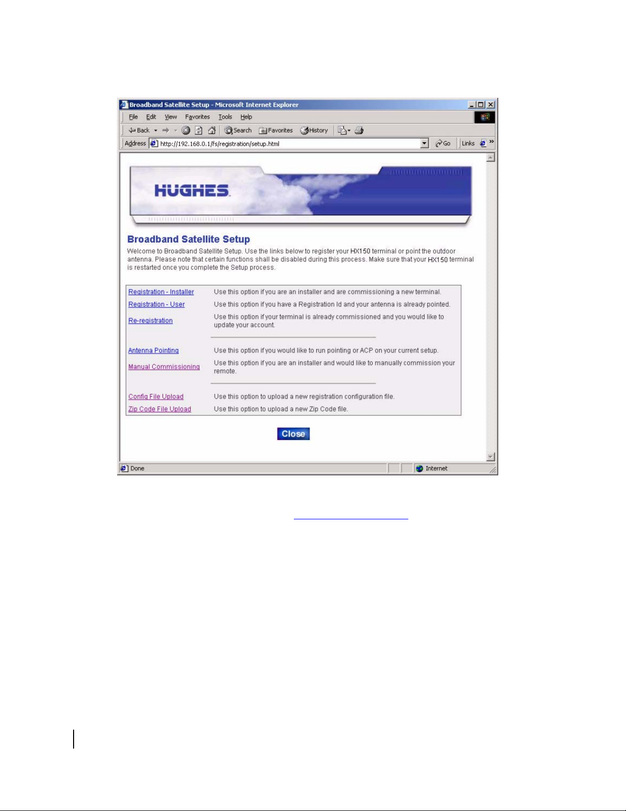
1. Open a web browser on the installer laptop.
2. Type http://192.168.0.1/fs/registration/
setup.html in the browser’s address or location bar and
press E
shown in
NTER to access the Broadband Satellite Setup screen
Figure 4.
Chapter 3 • Commissioning the HX200 satellite router
1038054-0001 Revision A.04 - Inspection Draft
15
TO BE REPLACED
16
Figure 4: HX200 Broadband Satellite Setup screen
3. Click Manual Commissioning. The HX200 Manual
Commissioning page appears (
4. Enter or select the appropriate satellite, VSAT (satellite
router), VSAT Transmit, LAN, and management parameters.
These parameters may be provided to you in an installation
specification, work order, or in another form of
communication from the installation point-of-contact.
Chapter 3 • Commissioning the HX200 satellite router
1038054-0001 Revision A.04 - Inspection Draft
Figure 5).
 Loading...