

Hughes HT1000 Installation Manual

HT1000 Satellite Modem
Installation Guide
1039110-0001
Revisi on A
October 17, 2012
11717 Exploration Lane, Germantown, MD 20876
Phone (301) 428-5500 Fax (301) 428-1868/2830

Copyright © 2012 Hughes Network Systems, LLC
All rights reserved. This publication and its contents are proprietary to Hughes Network
Systems, LLC. No part of this publication may be reproduced in any form or by any means
without the written permission of Hughes Network Systems, LLC, 11717 Exploration Lane,
Germantown, Maryland 20876.
Hughes Network Systems, LLC has made every effort to ensure the correctness and
completeness of the material in this document. Hughes Network Systems, LLC shall not be
liable for errors contained herein. The information in this document is subject to change
without notice. Hughes Network Systems, LLC makes no warranty of any kind with regard to this
material, including, but not limited to, the implied warranties of merchantability and fitness for
a particular purpose.
Hughes, Hughes Network Systems, HughesNet, and Jupiter are trademarks of Hughes Network
Systems, LLC. All other trademarks are the property of their respective owners.
Trademarks

Contents
Understanding safety alert messages. . . . . . . . . . . . . . . .7
Messages concerning personal injury . . . . . . . . . . . . . . . . . . . . . . 7
Messages concerning property damage . . . . . . . . . . . . . . . . . . . . 7
Safety symbols. . . . . . . . . . . . . . . . . . . . . . . . . . . . . . . . . . . . . . . . . 8
Additional symbols . . . . . . . . . . . . . . . . . . . . . . . . . . . . . . . . . . . . . 8
Chapter 1
Satellite modem overview. . . . . . . . . . . . . . . . . . . . . . . . .9
Introduction. . . . . . . . . . . . . . . . . . . . . . . . . . . . . . . . . . . . . . . . . . . 9
Terminology. . . . . . . . . . . . . . . . . . . . . . . . . . . . . . . . . . . . . . . . . . . 9
Scope . . . . . . . . . . . . . . . . . . . . . . . . . . . . . . . . . . . . . . . . . . . . . . . 10
Audience . . . . . . . . . . . . . . . . . . . . . . . . . . . . . . . . . . . . . . . . . . . . 10
Overview of tasks . . . . . . . . . . . . . . . . . . . . . . . . . . . . . . . . . . . . . 10
Chapter 2
Preparing for installation. . . . . . . . . . . . . . . . . . . . . . . . .11
Installation summary . . . . . . . . . . . . . . . . . . . . . . . . . . . . . . . . . . 11
Preparing for the installation . . . . . . . . . . . . . . . . . . . . . . . . . . 11
Installing the satellite modem . . . . . . . . . . . . . . . . . . . . . . . 12
Commissioning the modem and pointing the antenna . . . 12
Completing the installation . . . . . . . . . . . . . . . . . . . . . . . . . 12
Installation checklist . . . . . . . . . . . . . . . . . . . . . . . . . . . . . . . . . . . 12
IFL cables . . . . . . . . . . . . . . . . . . . . . . . . . . . . . . . . . . . . . . . . . . 12
Connectors and connections . . . . . . . . . . . . . . . . . . . . . . . . . . 12
Outdoors:. . . . . . . . . . . . . . . . . . . . . . . . . . . . . . . . . . . . . . . . 12
Power Source . . . . . . . . . . . . . . . . . . . . . . . . . . . . . . . . . . . . . . 13
Check neutral-ground (N-G) voltage . . . . . . . . . . . . . . . . . . . . 13
Grounding (modem, antenna, radio, and IFL) . . . . . . . . . . . . 13
Items required for installation . . . . . . . . . . . . . . . . . . . . . . . . . . . 13
Additional equipment. . . . . . . . . . . . . . . . . . . . . . . . . . . . . . . . 14
Conducting a site survey. . . . . . . . . . . . . . . . . . . . . . . . . . . . . . . . 14
Power supply information . . . . . . . . . . . . . . . . . . . . . . . . . . . . . . 14
Computer and networking requirements . . . . . . . . . . . . . . . . . . 16
Computer requirements. . . . . . . . . . . . . . . . . . . . . . . . . . . . . . 16
Networking and Internet browser requirements. . . . . . . . . . 16
Related components. . . . . . . . . . . . . . . . . . . . . . . . . . . . . . . . . . . 17
Antenna . . . . . . . . . . . . . . . . . . . . . . . . . . . . . . . . . . . . . . . . . . . 17
IFL cable . . . . . . . . . . . . . . . . . . . . . . . . . . . . . . . . . . . . . . . . . . . 17
Requirements for cables, connectors, and
• Contents
1039110-0001 Revision A
3

ground blocks . . . . . . . . . . . . . . . . . . . . . . . . . . . . . . . . . . . . 17
Labeling the IFL cable . . . . . . . . . . . . . . . . . . . . . . . . . . . . . . . . 18
Hub or similar network device . . . . . . . . . . . . . . . . . . . . . . . . . 18
Instructions for related components. . . . . . . . . . . . . . . . . . . . 18
Chapter 3
Installing the satellite modem . . . . . . . . . . . . . . . . . . . .21
Prerequisites for installing the modem. . . . . . . . . . . . . . . . . . 21
Selecting the modem installation location . . . . . . . . . . . . . . . . . 21
Ventilation and heat sources . . . . . . . . . . . . . . . . . . . . . . . . . . 22
Modem operating position . . . . . . . . . . . . . . . . . . . . . . . . . . . 22
Powering up the modem . . . . . . . . . . . . . . . . . . . . . . . . . . . . . . . 23
Connecting your laptop to the modem. . . . . . . . . . . . . . . . . . . . 24
Clearing the cache in Internet Explorer . . . . . . . . . . . . . . . . . 24
Clearing the cache in Mozilla FireFox . . . . . . . . . . . . . . . . . . . 24
Connecting the laptop . . . . . . . . . . . . . . . . . . . . . . . . . . . . . . . 25
Overview of entering installation parameters . . . . . . . . . . . . . . 26
Entering installation parameters . . . . . . . . . . . . . . . . . . . . . . . . . 30
Chapter 4
Installing outdoor equipment and antenna pointing . . . 3 3
Installing the IFL cable . . . . . . . . . . . . . . . . . . . . . . . . . . . . . . . . . 33
Routing and connecting the IFL cable . . . . . . . . . . . . . . . . . . . 33
IFL grounding requirement . . . . . . . . . . . . . . . . . . . . . . . . . . . 34
Labeling the IFL cable . . . . . . . . . . . . . . . . . . . . . . . . . . . . . . 34
Connecting the IFL cable to the modem . . . . . . . . . . . . . . . 35
Pointing the antenna . . . . . . . . . . . . . . . . . . . . . . . . . . . . . . . . . . 35
Coarse and fine pointing . . . . . . . . . . . . . . . . . . . . . . . . . . . . . 36
Pointing validation . . . . . . . . . . . . . . . . . . . . . . . . . . . . . . . . . . 36
Ranging . . . . . . . . . . . . . . . . . . . . . . . . . . . . . . . . . . . . . . . . . . . 36
• Contents
4
1039110-0001 Revision A
Chapter 5
Registering and commissioning the satellite modem . .39
Prerequisites for commissioning . . . . . . . . . . . . . . . . . . . . . . . . . 39
Monitoring the commissioning process . . . . . . . . . . . . . . . . . . . 39
Chapter 6
Validating the installation . . . . . . . . . . . . . . . . . . . . . . . .41
A quick look at the validation procedure . . . . . . . . . . . . . . . . . . 41
Chapter 7
Activating the terminal . . . . . . . . . . . . . . . . . . . . . . . . . .49
Chapter 8
Activating the HughesNet service. . . . . . . . . . . . . . . . . .53
Validating downloaded files . . . . . . . . . . . . . . . . . . . . . . . . . . . . . 53
Service activation prerequisites. . . . . . . . . . . . . . . . . . . . . . . . 55
Connecting the satellite modem to the customer’s
computer . . . . . . . . . . . . . . . . . . . . . . . . . . . . . . . . . . . . . . . . . . 55

Activation procedure . . . . . . . . . . . . . . . . . . . . . . . . . . . . . . . . . . 56
Digital Life Now download . . . . . . . . . . . . . . . . . . . . . . . . . . . . 61
Chapter 9
System Control Center. . . . . . . . . . . . . . . . . . . . . . . . . . .65
Accessing the System Control Center . . . . . . . . . . . . . . . . . . . . . 65
System Control Center home page . . . . . . . . . . . . . . . . . . . . . . . 65
Indicator links . . . . . . . . . . . . . . . . . . . . . . . . . . . . . . . . . . . . . . 67
Parameters bar . . . . . . . . . . . . . . . . . . . . . . . . . . . . . . . . . . . . . 68
Center panel text links and information . . . . . . . . . . . . . . . . . 69
HELP area. . . . . . . . . . . . . . . . . . . . . . . . . . . . . . . . . . . . . . . . 69
Side panel . . . . . . . . . . . . . . . . . . . . . . . . . . . . . . . . . . . . . . . . . 70
Small icon on System Control Center screens (Advanced
Pages). . . . . . . . . . . . . . . . . . . . . . . . . . . . . . . . . . . . . . . . . . . . . 70
Status and information screens . . . . . . . . . . . . . . . . . . . . . . . . 70
System Status page . . . . . . . . . . . . . . . . . . . . . . . . . . . . . . . . . . . . 71
System Information page . . . . . . . . . . . . . . . . . . . . . . . . . . . . . . . 72
Chapter 10
LEDS . . . . . . . . . . . . . . . . . . . . . . . . . . . . . . . . . . . . . . . . .73
Front panel LEDs . . . . . . . . . . . . . . . . . . . . . . . . . . . . . . . . . . . . . . 73
LAN port LEDs . . . . . . . . . . . . . . . . . . . . . . . . . . . . . . . . . . . . . . . . 75
Chapter 11
Advanced Pages . . . . . . . . . . . . . . . . . . . . . . . . . . . . . . . .77
Accessing the Advanced Pages . . . . . . . . . . . . . . . . . . . . . . . . . . 77
Expanding and collapsing menus. . . . . . . . . . . . . . . . . . . . . . . . . 78
Opening the Installation sub-menu . . . . . . . . . . . . . . . . . . . . . . . 78
State codes . . . . . . . . . . . . . . . . . . . . . . . . . . . . . . . . . . . . . . . . . . 79
Appendix A
Specifications . . . . . . . . . . . . . . . . . . . . . . . . . . . . . . . . . .83
HT1000 modem specifications. . . . . . . . . . . . . . . . . . . . . . . . . . . 83
Appendix B
Standards . . . . . . . . . . . . . . . . . . . . . . . . . . . . . . . . . . . . .85
Safety - Operating conditions for Canada . . . . . . . . . . . . . . . . . . 85
Repairs in Canada . . . . . . . . . . . . . . . . . . . . . . . . . . . . . . . . . . . . . 85
Electromagnetic interference (EMI) . . . . . . . . . . . . . . . . . . . . . . 86
FCC Part 15 . . . . . . . . . . . . . . . . . . . . . . . . . . . . . . . . . . . . . . . . 86
Canada Class B warning . . . . . . . . . . . . . . . . . . . . . . . . . . . . . . 86
Acronyms and abbreviations . . . . . . . . . . . . . . . . . . . . . .87
Index. . . . . . . . . . . . . . . . . . . . . . . . . . . . . . . . . . . . . . . . .89
• Contents
1039110-0001 Revision A
5

• Contents
6
1039110-0001 Revision A
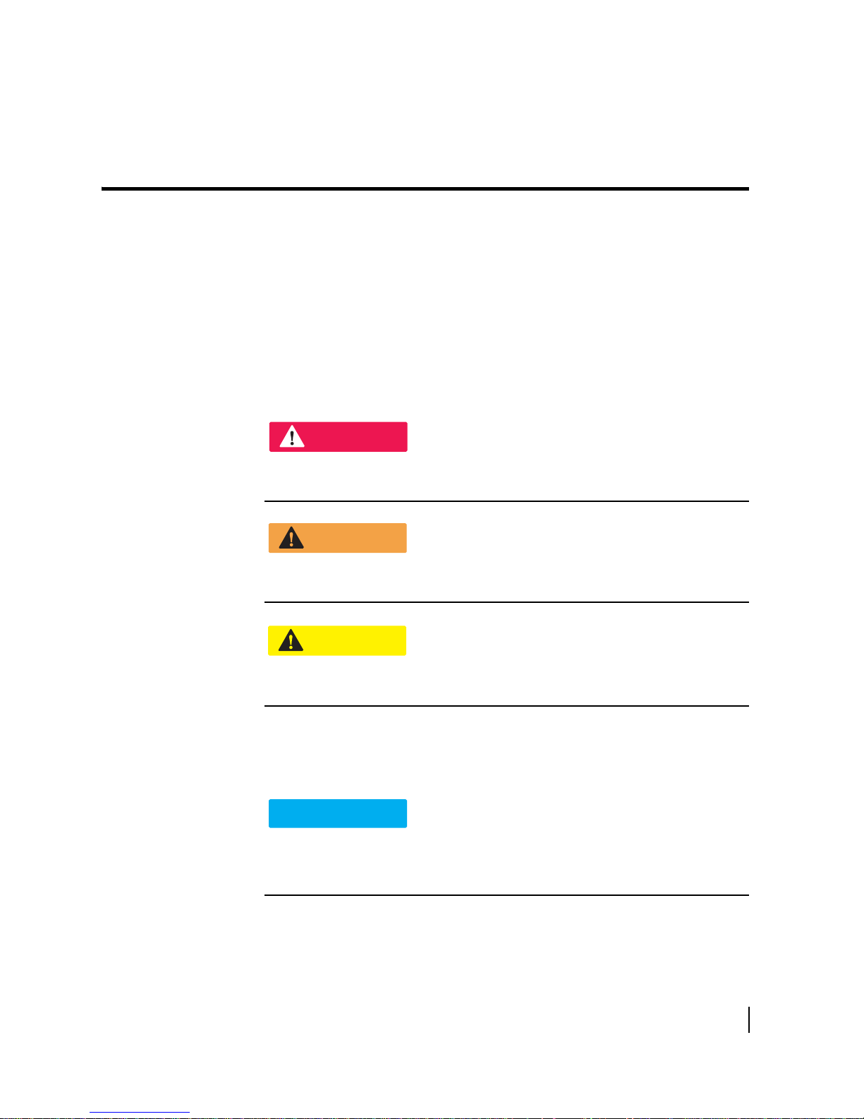
Understanding safety alert messages
DANGER
WARNING
CAUTION
NOTICE
Safety alert messages call attention to potential safety hazards and tell you how to
avoid them. These messages are identified by the signal words DANGER, WARNING,
CAUTION, or NOTICE, as illustrated below. To avoid possible property damage,
personal injury, or in some cases possible death, read and comply with all safety alert
messages.
Messages concerning personal injury
The signal words DANGER, WARNING, and CAUTION indicate hazards that could
result in personal injury or in some cases death, as explained below. Each of these
signal words indicates the severity of the potential hazard.
DANGER indicates a potentially hazardous situation which, if not avoided, will
result in death or serious injury.
WARNING indicates a potentially hazardous situation which, if not avoided,
could result in death or serious injury.
CAUTION indicates a potentially hazardous situation which, if not avoided, could
result in minor or moderate injury.
Messages concerning property damage
A NOTICE concerns property damage only.
NOTICE is used for advisory messages concerning possible property damage,
product damage or malfunction, data loss, or other unwanted results—but not
personal injury.
• Understanding safety alert messages
1039110-0001 Revision A
7

Safety symbols
The generic safety alert symbol
calls attention to a potential personal injury hazard. It appears next to the DANGER,
W
ARNING, and CAUTION signal words as part of the signal word label. Other symbols
may appear next to DANGER, WARNING, or CAUTION to indicate a specific type of
hazard (for example, fire or electric shock). If other hazard symbols are used in this
document they are identified in this section.
Additional symbols
This document uses the following hazard symbol:
Indicates a safety message that concerns a potential
electric shock hazard.
• Understanding safety alert messages
8
1039110-0001 Revision A
Introduction
Chapter 1
Satellite modem overview
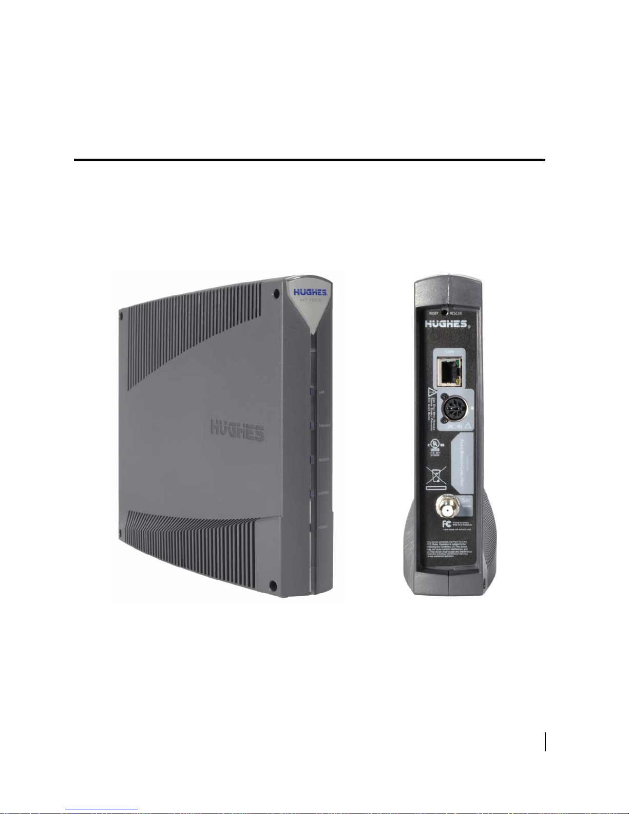
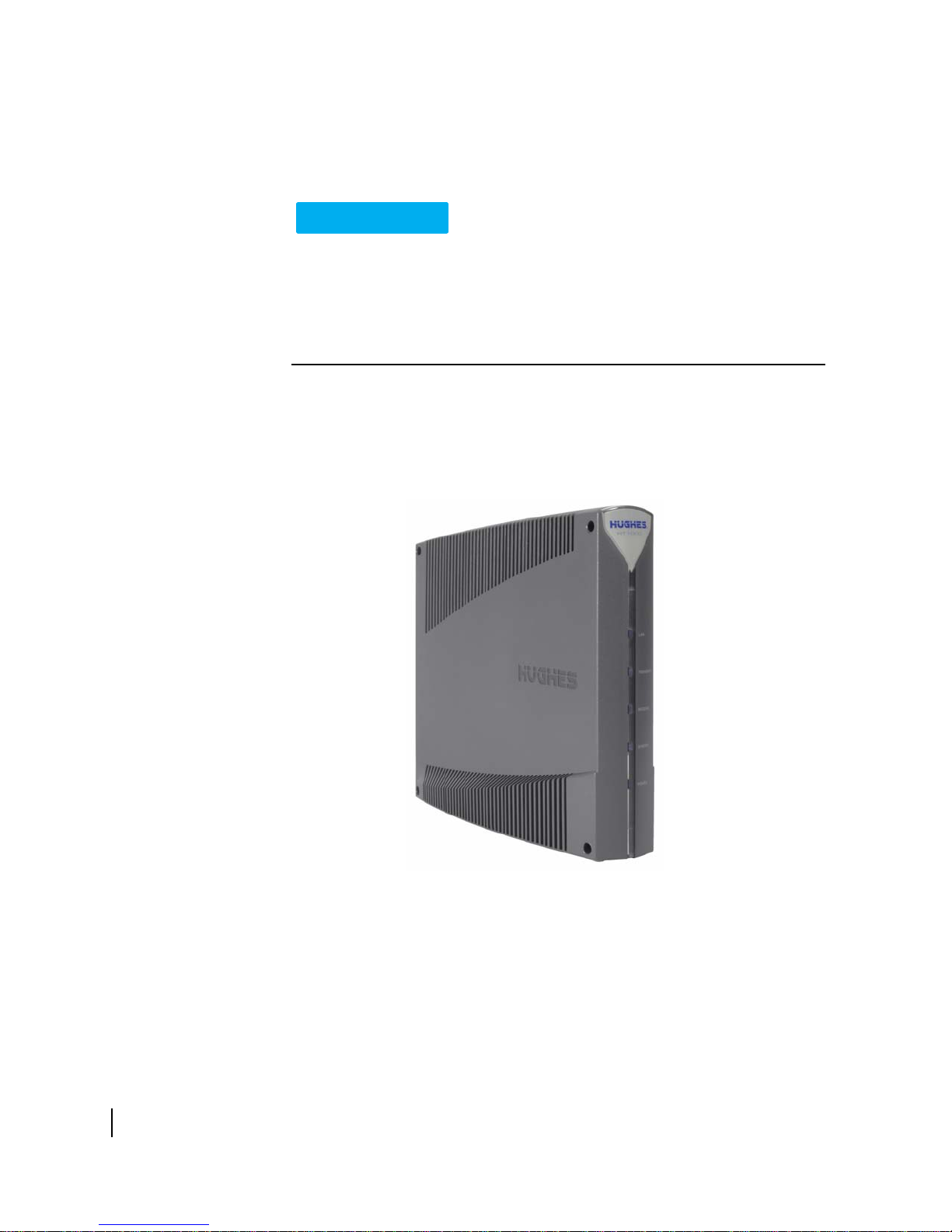
The HT1000 satellite modem provides Internet service by connecting a computer to a
Ka-band bent-pipe satellite network. The modem’s Ethernet port connects to a
computer or local area network (LAN). Figure 1 shows the HT1000 from the front and
back.
Figure 1: HT1000 satellite modem front and back
Terminology
In this installation guide:
ellite modem and modem both refer to the HT1000 satellite modem.
• Sat
Chapter 1 • Satellite modem overview
1039110-0001 Revision A
9

• Installer Support refers to organizations that provide assistance to professional
installers of Hughes satellite equipment. If you do not know who provides your
support, contact Hughes dealer services.
Scope
This installation guide explains how to install, commission, activate, and
troubleshoot the HT1000 satellite modem. It also contains reference information to
assist you in this process.
Audience
This guide is intended for professional installers. It may also be useful for:
• T
• Call cen
Overview of tasks
Figure 2 gives an overview of the installation, commissioning, and activation tasks.
Each task may be composed of numerous subtasks.
rainers who train installers
ter operators who respond to customers' calls
10
Chapter 1 • Satellite modem overview
1039110-0001 Revision A
Figure 2: Summary of tasks
This chapter describes preparations for installing the satellite modem. Review this
information before you install the satellite modem, antenna assembly, antenna
mount, or inter-facility link (IFL) cable.
To install the satellite modem, you need the Installation Reference Sheet, which
ontains installation parameters and other information specific to your site. Print the
c
Installation Reference Sheet from your installation support web site.
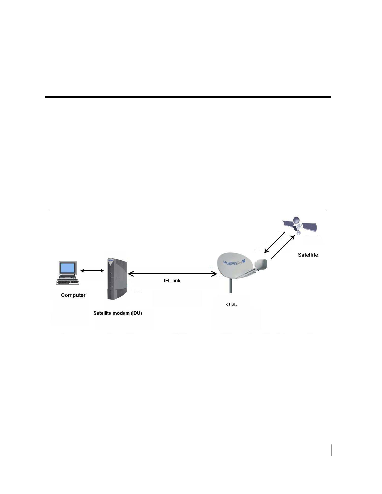
Installation summary
The satellite modem is the small indoor unit (IDU). The outdoor unit (ODU) includes
the antenna and radio assembly. An IFL cable connects the indoor unit to the outdoor
unit, as shown in Figure 3.
Chapter 2
Preparing for installation
Figure 3: Satellite modem and related components
Preparing for the installation
• Make sure you have all items required for installation, including the Installation
Reference Sheet, all equipment to be installed, and required tools for the
outdoor equipment.
• Mak
and networking requirements on
e sure the customer's computer meets the requirements listed in Computer
page 16.
Chapter 2 • Preparing for installation
1039110-0001 Revision A
11

• Conduct a site survey.
• Assemble and install the antenna and radio as instructed in the antenna
installation guide.
Installing the satellite modem
• Connect the IFL cable.
• Clear your cache of your Web browser.
• Connect the modem to your laptop.
• Connect the power supply.
• Power up the modem and observe the LEDs to verify normal operation.
Commissioning the modem and pointing the antenna
• Upload the sbc.cfg file (if you are instructed to upload it).
• Enter the parameters.
• Point the antenna.
• Register the satellite modem.
Completing the installation
• Run OVT (Onsite Validation Tool)
• Connect the modem to the customer's computer for activation.
• Confirm that the customer can connect to the Web.
Installation checklist
To help ensure a successful installation, pay careful attention to the items listed
below as you install the satellite modem, antenna, and the IFL cable.
IFL cables
For specific cable information see Tab le 2 on page 18.
• Use only Hughes-approved cables.
• Do not exceed maximum length for the outdoor unit (ODU) type, cable type, and
cable part number.
• Do not exceed the cable bend radius.
• Properly terminate cables.
Connectors and connections
Use only connector types approved for cable type used. Check all connections for
tightness.
Outdoors:
• Make sure F connectors connected to the radio assembly are tightened to 20
inch-lb torque.
• Carefully follow waterproofing procedures, using dielectric grease and
Hughes-approved weatherproof tape.
12
Chapter 2 • Preparing for installation
1039110-0001 Revision A

Power Source
Before connecting the modem power supply to the AC power source, use an AC
outlet tester to verify that the outlet is wired correctly. Wiring problems may include:
• Hot and neutral wires reversed
• Neutral and ground wires reversed
• Open ground (incomplete connection)
• Open neutral (incomplete connection)
If the outlet is wired improperly, notify the customer you are not permitted to
connect the system to a faulty outlet. Do not proceed with installation until a
properly wired outlet is provided.
Check neutral-ground (N-G) voltage
With a digital multimeter set to AC voltage, measure the voltage between neutral
and ground at the AC power outlet. If the N-G voltage measures 2 VAC or greater,
advise the customer to have an electrician evaluate the electrical power outlet. N-G
voltages may have a negative impact on the performance of electronic equipment.
Grounding (modem, antenna, radio, and IFL)
• Adhere to Hughes grounding requirements.
• Use only approved ground wires, ground blocks, lugs, and clamps.
• For detailed information refer to the appropriate FSB, as listed in Tab le 2 on
page 18.
Items required for installation
To install the HT1000 satellite modem, you need:
• HT1000 satellite modem
• Power supply (provided in the shipping carton)
• Surge protector (recommended), provided by the customer
• Cat-5 Ethernet cable
• sbc.cfg file (if you are instructed to upload it)
• Installation Reference Sheet (provided to you)
• Welcome to the HughesNet Quick Start Guide (1039433-0001) (to give to the
customer)
Chapter 2 • Preparing for installation
1039110-0001 Revision A
13

Additional information:
• sbc.cfg file - If needed, you can download the most current sbc.cfg file from your
installation support web site.
• SAN and PIN - Identification numbers are required to register the satellite
modem. Customers who purchased their system from a Hughes retail channel in
the United States or Canada receive an order confirmation e-mail containing
their site account number (SAN) and personal identification number (PIN).
Additional equipment
• Antenna
• Hughes DiSecQ antenna pointing tool (DAPT2)
• IFL cable, cable connectors, and ground blocks
For more information on these items, see Related components on page 17.
No tools are required to install the modem. For tools needed to install the antenna
mount and antenna and point the antenna, see:
• Antenna Site Preparation and Mount Installation Guide (1035678-0001)
• The installation guide for the antenna model you are installing
Conducting a site survey
Survey the customer site to confirm that the location meets the requirements for
installation of the satellite modem. For complete site survey information, including
site requirements, see the Antenna Site Preparation and Mount Installation Guide
(1035678-0001).
The key site survey tasks related to installation of the satellite modem are:
1. Ensure there is an unobstructed line of sight to the satellite specified on the
Installation Reference Sheet.
2. Review the Installation Reference Sheet for site-specific instructions.
Power supply information
The satellite modem shipping carton contains the power supply information. Figure 4
on page 15 shows a sample power supply.
14
Chapter 2 • Preparing for installation
1039110-0001 Revision A
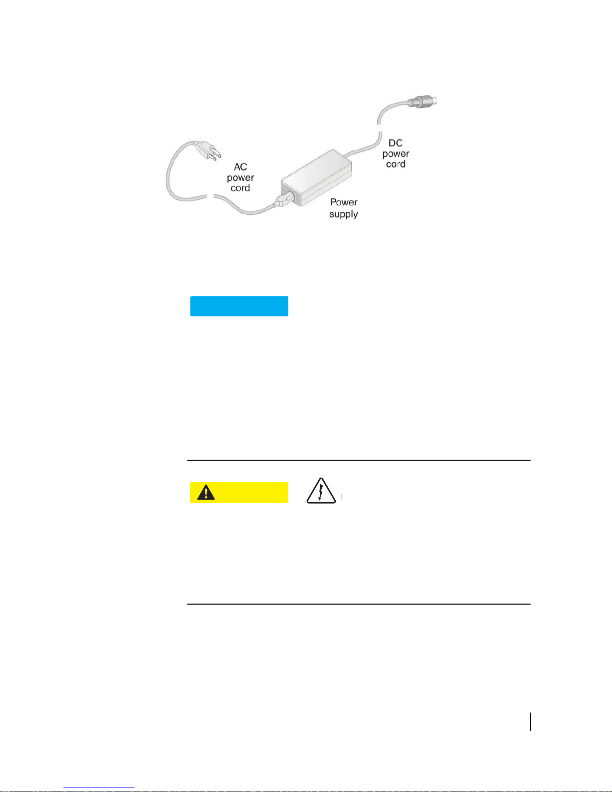
Figure 4: AC power supply
NOTICE
CAUTION
Before proceeding, make sure you have the correct power supply. Check the part
number on the power supply as listed in Table 1 on page 16.
• Always use the power supply provided with the satellite modem. The
modem's performance may suffer if the wrong power supply is used.
• Connect the AC/DC power supply to a 110 Voltage Alternating Current (VAC)
three-wired grounded outlet. A suitable surge protector is recommended to
protect the satellite modem from possible damage due to power surges.
ays connect the DC power cord to the HT1000 rear panel before
• Alw
applying power to the power supply. If you apply power to the power
supply and then connect the DC power cord, the satellite modem may not
perform properly and could be damaged.
serve the power standards and requirements of the country where it is
• Ob
installed.
If there is any reason to remove power from the satellite modem, always unplug
the AC power cord from the power source (power outlet, power strip, or surge
protector). Do not remove the DC power cord from the modem's rear panel.
Doing so could result in an electrical shock or damage the modem.
When you re-apply power to the modem, plug the AC power cord into the
power source.
Chapter 2 • Preparing for installation
1039110-0001 Revision A
15

Table 1: Power supply specifications
CAUTION
Power supply
type
AC/DC, 46 W
P/N 1502015
HT1000 satellite modem with 1
W radio only
Part number Electrical requirements
Computer and networking requirements
This section lists the requirements for the computer or other device, network, and
browser to be used with the satellite modem.
Computer requirements
The HT1000 satellite modem can be used with any device that supports Internet
Protocl (IP) and has a 10/100 BaseT Ethernet LAN port. Typically, the modem is
connected to a customer's computer. However, the HT1000 is self-hosted; it does not
require a computer for any of its functions.
Requirements for the computer to be used with the satellite modem are the same
or the laptop computer you use to install the modem. The computer should meet
f
the minimum requirements specified by the computer operating system
manufacturer and the following networking and browser requirements. Make sure
your laptop is configured to support DHCP.
Input line voltage: 100 - 130 V,
1.5 A maximum
Input line frequency: 60 Hz AC
Rated power consumption: 46 W
Note: The
satellite modem can be used with a Mac computer that meets these
requirements, but Mac computers are not supported as a tool for installing
the satellite modem.
Networking and Internet browser requirements
• Ethernet port
thernet Network interface card (NIC) installed on at least one computer, 10/100
• E
BaseT
• Ethernet cable (provided)
eb browser such as Internet Explorer with proxy settings disabled
• A w
Connecting a network
modem, this requires an Ethernet hub or other such device. The customer must
supply and configure the hub and cables. Required IP address information is obtained
during commissioning.
Do not connect the power supply to the satellite modem, or connect the power
supply to a power source until you are instructed to do so.
- If the customer wants to connect a network to the satellite
16
Chapter 2 • Preparing for installation
1039110-0001 Revision A

Related components
CAUTION
NOTICE
Antenna
You must assemble and install the antenna before you install the satellite modem.
You point the antenna as part of the modem commissioning process.
Only a trained professional installer should install the outdoor antenna
assembly. In the United States, the Federal Communications Commission (FCC)
requires professional installation and service of the antenna assembly because
it transmits radio frequency (RF) energy.
The HT1000 satellite modem can be used with a 0.69 m, 0.74 m, or 0.98 m, two-way
satellite antenna. The antenna assembly is shipped in a separate box.
The main source of information on the antenna is the antenna installation guide. If
ou do not have the antenna installation guide, refer to your Installation Reference
y
Sheet; then locate the guide for that model on your installation support web site.
IFL cable
Before you can install the satellite modem, you must route the coaxial IFL cable
between the indoor satellite modem location and the antenna. Then you connect the
modem and the antenna by connecting the IFL cable to both components.
The routing path of the IFL cable between the modem and the antenna depends on
the bui
Guide (1035678-0001) give guidelines for installing IFL cables.
Requirements for cables, connectors, and ground blocks
You must use approved cable types and connectors to connect the modem to the
outdoor satellite antenna. For grounding, you must use approved ground blocks and
grounding connectors. For detailed specifications and information on these
components, see the documents listed in Tab le 2 on page 18.
When you install the antenna assembly, read and follow all safety alerts and
instructions in the antenna installation guide and in the Antenna Site
Preparation and Mount Installation Guide (1035678-0001).
lding configuration. The Antenna Site Preparation and Mount Installation
Chapter 2 • Preparing for installation
1039110-0001 Revision A
17
The coaxial IFL cable and the ground block to which they are connected must meet
WARNING
the grounding requirements specified in the following warning:
You must comply with applicable local codes and the grounding requirements in
Field Service Bulletin (FSB), HNS Broadband Requirements for RG-6 and RG-11
IFL Cable Connectors, Ground Blocks, and Ground Block Location
(FSB_050518_01). Improper grounding can result in electric shock injury,
property damage, and/or poor modem performance.
Labeling the IFL cable
Label the IFL cable at the outdoor point-of-entry and at the indoor location where
the satellite modem is installed as follows:
Wrap a piece of blue electrical tape around the cable, and mark SAT on the tape.
Hub or similar network device
The customer must supply and configure the network device, including required
cables, according to the device manufacturer's documentation. Required IP address
information is obtained during modem commissioning.
Instructions for related components
This installation guide covers only installation of the satellite modem. For installation
instructions for other components, see Table 2 on page 18.
You can view or download these documents at
Installer Login Click Here! on your installation support web site. If you cannot log in,
contact your installer support for access to these documents.
Table 2: Related installation documents
Component or topic Where to find instructions
Safety (all components) Site survey, Site
preparation, Antenna mounts, IFL cable
https://dwayinstalls.hns.com/. Click
Antenna Site Preparation and Mount
Installation Guide (1035678-0001)
18
Chapter 2 • Preparing for installation
1039110-0001 Revision A
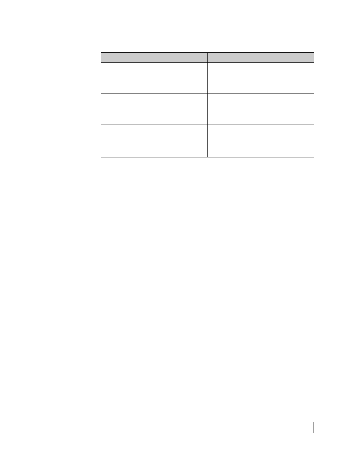
Table 2: Related installation documents
Component or topic Where to find instructions
IFL cables (specifications, approved types,
maximum lengths)
Field Service Bulletin (FSB), IFL Cable
Approved List (with lengths) for
Jupiter/HT1000/HT1100 Domestic
Installations
IFL cable connectors, Grounding, Ground
blocks
Antenna, antenna pointing, Radio assembly See the antenna installation guide for the
HNS Broadband Requirements for RG-6
and RG-11 IFL Cable Connectors, Ground
Blocks, and Ground Block Location
(FSB_050518_01)
specific antenna model you are installing.
For Ka-band antennas, see the Jupiter
Antenna Pointing Guide (1039429-0001)
(FSB_0120909_01).
Chapter 2 • Preparing for installation
1039110-0001 Revision A
19

20
Chapter 2 • Preparing for installation
1039110-0001 Revision A

Installing the satellite modem
Installation of the HT1000 satellite modem consists of physical installation followed
by a highly automated process that fully prepares the modem for operation on the
satellite network. Installation tasks include:
• Physical installation and power-up
• Entering required installation parameters
• Pointing the antenna
• Monitoring the commissioning process
• Service activation
The installation software is factory pre-installed in the satellite modem and
automatically updated as part of the installation process. You access the installation
software through your computer’s browser to perform installation tasks.
Prerequisites for installing the modem
Make sure the installation location meets the following requirements concerning
ventilation and heat sources.
• Do not block any of the modem's ventilation openings.
• Leave 6 inches of space around the top and sides of the modem to ensure
adequate ventilation and prevent overheating.
• Do not place the modem near a heat source such as direct sunlight, a radiator,
heat register or vent, oven, stove, amplifier, or other apparatus that produces
heat.
Chapter 3
Selecting the modem installation location
Select a location for the satellite modem that accommodates all required cable
connections, including the connection to the power source.
Chapter 3 • Installing the satellite modem
1039110-0001 Revision A
21
Ventilation and heat sources
NOTICE
Make sure the installation location meets the following requirements concerning
ventilation and heat sources.
• Do not block any of the modem's ventilation openings.
• Leave 6 inches of space around the top and sides of the modem to ensure
adequate ventilation and prevent overheating.
o not place the modem near a heat source such as direct sunlight, a
• D
radiator, heat register or vent, oven, stove, amplifier, or other apparatus
that produces heat.
Modem operating position
Install and operate the HT1000 modem only in the upright vertical position resting
on its built-in base as shown in Figure 5. Any other position could result in insufficient
ventilation, overheating, and malfunction.
22
Chapter 3 • Installing the satellite modem
1039110-0001 Revision A
Figure 5: HT1000 in correct vertical position
Powering up the modem
For this task you must have the satellite modem and the correct power supply. To
make sure you have the correct power supply, see Ta bl e 1 on page 16.
Test the power outlet and power up the satellite modem:
1. Use an AC outlet tester to verify that the power outlet is wired correctly. Wiring
oblems may include:
pr
• Hot and neutr
• Neutr
• O
• O
If the outlet is wired improperly, notify the customer that you are not permitted to
onnect the system to a faulty outlet. Do not proceed with the installation until a
c
properly wired outlet is provided.
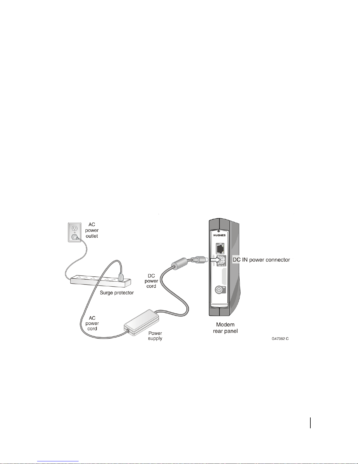
2. Connect the DC power cord to the modem's DC IN connector, as shown in
3. Connect the surge connector (recommended) to an AC power outlet.
4. Apply power by connecting the AC power cord to the surge connector. The
al and ground wires reversed
pen ground (incomplete connection)
pen neutral (incomplete connection)
Figure 6. Connect the AC power cord to the three-prong connector on the
modem's power supply.
ower LED turns on, and various LEDs turn on and off as the modem performs a
P
self-test and transitions to boot phase.
al wires reversed
Figure 6: Powering up the modem
Chapter 3 • Installing the satellite modem
1039110-0001 Revision A
23
A suitable surge protector is recommended to protect the satellite modem from
NOTICE
possible damage due to power surges.
Connecting your laptop to the modem
For this task you need an Ethernet cable to connect your laptop to the HT1000
modem.
To access the satellite modem so you can perform the required installation
ocedures, you connect your laptop computer to the modem.
pr
Before connecting your laptop to the modem, it is important you clear your
mputer’s cache.
co
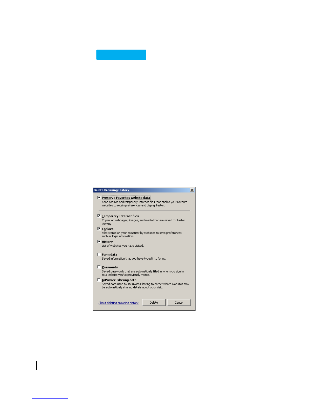
Clearing the cache in Internet Explorer
1. Press the Ctrl + Shift + Del keys. The Delete Browsing History screen appears.
2. Select the options as shown in Figure 7.
3. Click Delet
e.
Figure 7: Internet Explorer Delete Browsing History screen
Clearing the cache in Mozilla FireFox
1. Press the Ctrl + Shift + Del keys. The Clear All History screen appears.
24
Chapter 3 • Installing the satellite modem
1039110-0001 Revision A
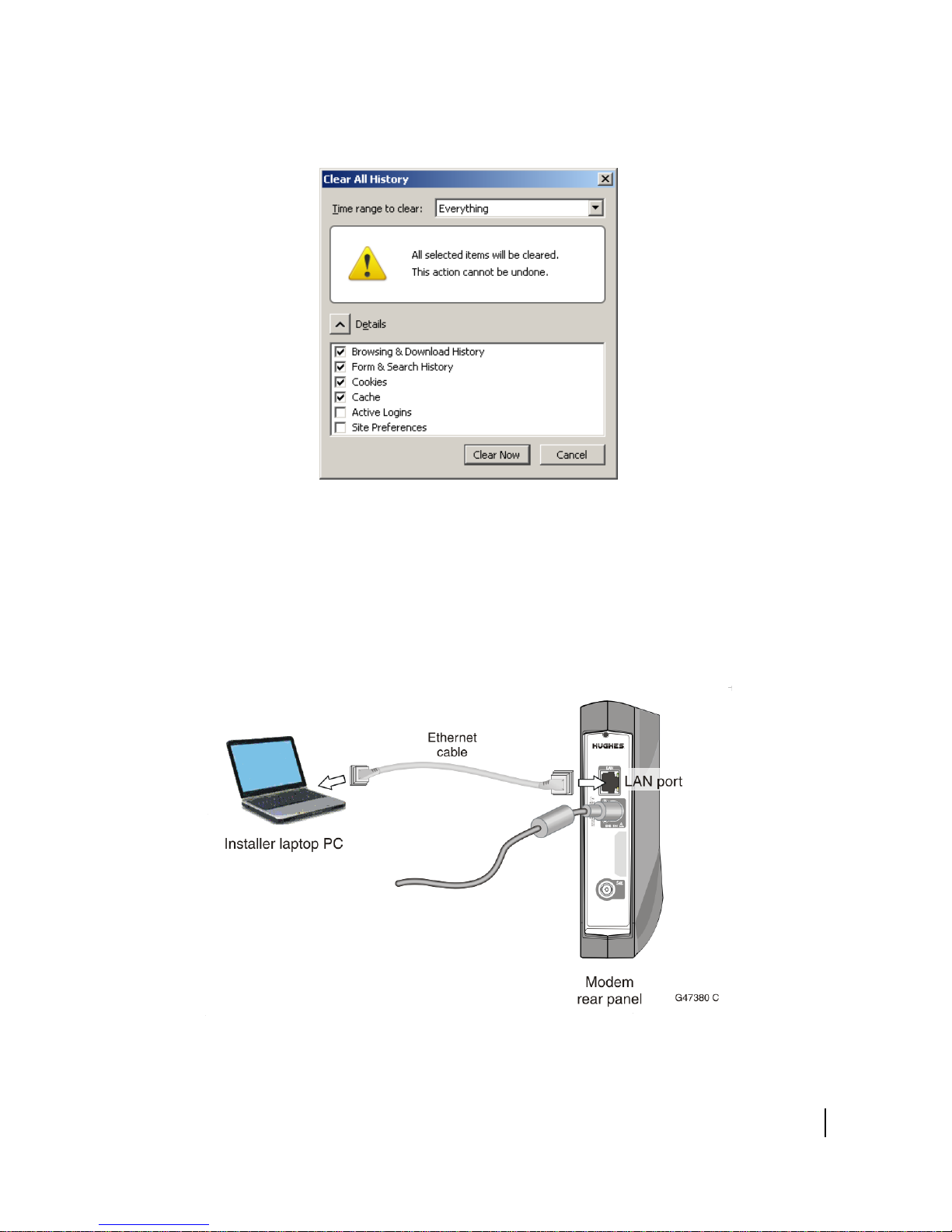
2. Select the options as shown in Figure 8.
3. Click Clea
Figure 8: Mozilla FireFox Clear All History screen.
r Now.
Connecting the laptop
Connect your laptop to the modem:
1. Use an Ethernet cable to connect your laptop computer directly to the modem's
LAN port, as sho
through an Ethernet modem or switch.
wn in Figure 9. Do not connect the laptop to the modem
Figure 9: Connecting your laptop to the modem
Chapter 3 • Installing the satellite modem
1039110-0001 Revision A
25
2. Make sure that neither the satellite modem or the customer's computer are
connected to an Ethernet modem or switch.
3. If you are running firewall software on the laptop computer, disable it until you
omplete installation of the modem. The LAN LED on the front of the modem
c
should now be on.
Overview of entering installation parameters
Successful installation of the satellite modem depends on your tasks, network and
installation software, and interaction between the satellite modem and the Network
Operations Center (NOC). After powering up the modem, enter the required
parameters and then complete the antenna pointing.
The following apply to the screen illustrations in this guide:
he screen illustrations are examples. Values shown in these illustrations may
• T
not apply to the satellite modem you are installing. Do not use values shown to
install or configure the modem unless the instructions say to do so.
n some screens and in some messages you may see the word modem or the
• O
abbreviation VSAT. Both refer to the HT1000 satellite modem.
• Screen and p
computer monitor.
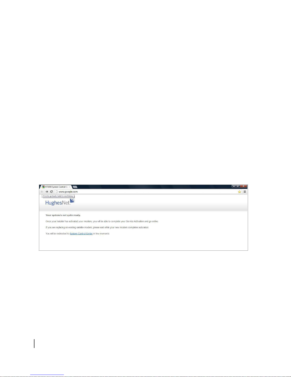
1. Open a browser on your laptop. The Your system is not quite ready screen
app
ears as shown in Figure 10. This is the first screen of the commissioning
process.
age are both used to refer to the information displayed on your
26
Chapter 3 • Installing the satellite modem
1039110-0001 Revision A
Figure 10: System not ready screen.
2. The System Control Center home page appears as shown in Figure 11.
Figure 11: System Control Center home page
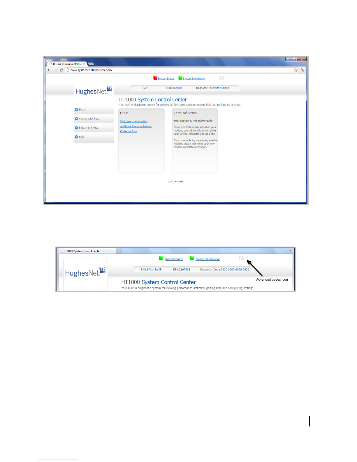
4. Click the Advanced Pages icon at the top of the page as shown in Figure 12. The
Advanced Configuration and Statistics page appears as shown in Figure 13.
Figure 12: Advanced pages icon
Chapter 3 • Installing the satellite modem
1039110-0001 Revision A
27
 Loading...