

Hughes HN9260 Installation Manual

HN9260 Satellite Modem
Installation Guide
1039434-0001
Revisi on A
March 30, 2012
11717 Exploration Lane, Germantown, MD 20876
Phone (301) 428-5500 Fax (301) 428-1868/2830

Copyright ©2012 Hughes Network Systems, LLC
All rights reserved. This publication and its contents are proprietary to Hughes Network
Systems, LLC. No part of this publication may be reproduced in any form or by any means
without the written permission of Hughes Network Systems, LLC, 11717 Exploration Lane,
Germantown, Maryland 20876.
Hughes Network Systems, LLC has made every effort to ensure the correctness and
completeness of the material in this document. Hughes Network Systems, LLC shall not be
liable for errors contained herein. The information in this document is subject to change
without notice. Hughes Network Systems, LLC makes no warranty of any kind with regard to this
material, including, but not limited to, the implied warranties of merchantability and fitness for
a particular purpose.
Hughes, Hughes Network Systems, and HughesNet are trademarks of Hughes Network Systems,
LLC. All other trademarks are the property of their respective owners.
Trademarks

Contents
Understanding safety alert messages. . . . . . . . . . . . . . . .7
Messages concerning personal injury . . . . . . . . . . . . . . . . . . . . . . 7
Messages concerning property damage . . . . . . . . . . . . . . . . . . . . 7
Safety symbols. . . . . . . . . . . . . . . . . . . . . . . . . . . . . . . . . . . . . . . . . 8
Additional symbols . . . . . . . . . . . . . . . . . . . . . . . . . . . . . . . . . . . 8
Chapter 1
Satellite modem overview. . . . . . . . . . . . . . . . . . . . . . . . .9
Scope of this installation guide . . . . . . . . . . . . . . . . . . . . . . . . . . 10
Satellite modem specifications . . . . . . . . . . . . . . . . . . . . . . . . . 10
Chapter 2
Preparing for installation. . . . . . . . . . . . . . . . . . . . . . . . .11
Installation summary . . . . . . . . . . . . . . . . . . . . . . . . . . . . . . . . . . 11
Installation checklist . . . . . . . . . . . . . . . . . . . . . . . . . . . . . . . . . . . 13
Items required for installation . . . . . . . . . . . . . . . . . . . . . . . . . . . 14
Conducting a site survey. . . . . . . . . . . . . . . . . . . . . . . . . . . . . . . . 15
Power supply information . . . . . . . . . . . . . . . . . . . . . . . . . . . . . . 15
Computer and networking requirements . . . . . . . . . . . . . . . . . . 17
Computer requirements. . . . . . . . . . . . . . . . . . . . . . . . . . . . . . 17
Networking and Internet browser requirements. . . . . . . . . . 17
Related components. . . . . . . . . . . . . . . . . . . . . . . . . . . . . . . . . . . 18
Antenna . . . . . . . . . . . . . . . . . . . . . . . . . . . . . . . . . . . . . . . . . . . 18
IFL Cables . . . . . . . . . . . . . . . . . . . . . . . . . . . . . . . . . . . . . . . . . . 19
Hub or similar network device . . . . . . . . . . . . . . . . . . . . . . . . . 19
Instructions for related components. . . . . . . . . . . . . . . . . . . . 20
Chapter 3
Installing the satellite modem . . . . . . . . . . . . . . . . . . . .21
Prerequisites for installing the modem. . . . . . . . . . . . . . . . . . . . 21
Selecting the modem installation location . . . . . . . . . . . . . . . . . 21
Ventilation and heat sources . . . . . . . . . . . . . . . . . . . . . . . . . . 22
Modem operating position . . . . . . . . . . . . . . . . . . . . . . . . . . . . . 22
Connecting the transmit and receive cables. . . . . . . . . . . . . . . . 23
Connecting the installer laptop to the modem . . . . . . . . . . . . . 23
Connecting the power supply . . . . . . . . . . . . . . . . . . . . . . . . . . . 24
Connecting an AC/DC power supply . . . . . . . . . . . . . . . . . . . . 24
Connecting and assembling a DC/DC power supply . . . . . . . 26
Powering up the modem . . . . . . . . . . . . . . . . . . . . . . . . . . . . . . . 27
AC/DC power supply . . . . . . . . . . . . . . . . . . . . . . . . . . . . . . . . . 27
• Contents
1039434-0001 Revision A
3

DC/DC power supply. . . . . . . . . . . . . . . . . . . . . . . . . . . . . . . . . 27
LEDS on power-up. . . . . . . . . . . . . . . . . . . . . . . . . . . . . . . . . . . . . 27
Chapter 4
Commissioning the satellite modem. . . . . . . . . . . . . . . .29
Satellite-based commissioning . . . . . . . . . . . . . . . . . . . . . . . . . . 29
Obtaining an IP address from the satellite modem . . . . . . . . 30
Verifying the Ethernet connection . . . . . . . . . . . . . . . . . . . . . 30
Uploading the sbc.cfg file to the satellite modem . . . . . . . . . 32
Entering commissioning parameters. . . . . . . . . . . . . . . . . . . . 34
Receive antenna pointing - Ka-band . . . . . . . . . . . . . . . . . . . . 45
Receive antenna pointing - Ku-band . . . . . . . . . . . . . . . . . . . . 49
Transmit antenna pointing - Ku-band . . . . . . . . . . . . . . . . . . . 50
Registering the satellite modem . . . . . . . . . . . . . . . . . . . . . . . 53
Registering in the United States or Canada . . . . . . . . . . . . . . 55
Registering outside the United States and Canada . . . . . . . . 56
Manual commissioning. . . . . . . . . . . . . . . . . . . . . . . . . . . . . . . . . 58
Entering parameters-manual commissioning. . . . . . . . . . . . . 59
Manually accessing the antenna pointing screens. . . . . . . . . 61
Software download-manual commissioning . . . . . . . . . . . . . 61
Chapter 5
Completing the installation . . . . . . . . . . . . . . . . . . . . . . .63
Confirming that the satellite modem’s files are up to date . . . 63
Connecting the satellite modem to the customer's computer . 64
Verify that the customer can browse the Internet . . . . . . . . . . 65
Printing the System Information page . . . . . . . . . . . . . . . . . . . . 65
Creating a shortcut to the System Control Center . . . . . . . . . . . 65
Installation complete . . . . . . . . . . . . . . . . . . . . . . . . . . . . . . . . . . 66
• Contents
4
1039434-0001 Revision A
Chapter 6
System control center . . . . . . . . . . . . . . . . . . . . . . . . . . .67
Accessing the System Control Center . . . . . . . . . . . . . . . . . . . . . 67
System Control Center home page . . . . . . . . . . . . . . . . . . . . . . . 67
Text links . . . . . . . . . . . . . . . . . . . . . . . . . . . . . . . . . . . . . . . . . . 68
Common features on System Control Center screens . . . . . . . . 69
Button links . . . . . . . . . . . . . . . . . . . . . . . . . . . . . . . . . . . . . . . . 70
System Status button . . . . . . . . . . . . . . . . . . . . . . . . . . . . . . . . 71
IPSec icon. . . . . . . . . . . . . . . . . . . . . . . . . . . . . . . . . . . . . . . . . . 72
Links in the left panel . . . . . . . . . . . . . . . . . . . . . . . . . . . . . . . . 72
Small icon on System Control Center screens . . . . . . . . . . . . 73
Status and information screens . . . . . . . . . . . . . . . . . . . . . . . . 73
Features a customer may not see . . . . . . . . . . . . . . . . . . . . . . . . 75
System Status page . . . . . . . . . . . . . . . . . . . . . . . . . . . . . . . . . . . . 75
Reception Information page . . . . . . . . . . . . . . . . . . . . . . . . . . . . 77
Examining receive status . . . . . . . . . . . . . . . . . . . . . . . . . . . . . 78

Transmission Information page . . . . . . . . . . . . . . . . . . . . . . . . . . 79
Examining transmit status . . . . . . . . . . . . . . . . . . . . . . . . . . . . 80
System Information page . . . . . . . . . . . . . . . . . . . . . . . . . . . . . . . 81
Help page. . . . . . . . . . . . . . . . . . . . . . . . . . . . . . . . . . . . . . . . . . . . 82
System Control Center tools for troubleshooting . . . . . . . . . . . 83
Chapter 7
LEDs . . . . . . . . . . . . . . . . . . . . . . . . . . . . . . . . . . . . . . . . .85
Front panel LEDs . . . . . . . . . . . . . . . . . . . . . . . . . . . . . . . . . . . . . . 85
LAN port LEDs . . . . . . . . . . . . . . . . . . . . . . . . . . . . . . . . . . . . . . . . 87
Using LEDs for troubleshooting . . . . . . . . . . . . . . . . . . . . . . . . . . 87
Chapter 8
Troubleshooting . . . . . . . . . . . . . . . . . . . . . . . . . . . . . . . .89
Important troubleshooting information . . . . . . . . . . . . . . . . 90
Troubleshooting reference diagram . . . . . . . . . . . . . . . . . . . . . . 90
Troubleshooting common problems . . . . . . . . . . . . . . . . . . . . . . 91
Cannot access the Internet . . . . . . . . . . . . . . . . . . . . . . . . . . . . . 91
Confirming that the satellite modem is commissioned. . . . . 92
Confirming the receive signal . . . . . . . . . . . . . . . . . . . . . . . . . 93
Confirming the transmit signal . . . . . . . . . . . . . . . . . . . . . . . . 93
Confirming that TCP Acceleration is operational . . . . . . . . . . 94
Confirming that Web Acceleration is operational . . . . . . . . . 95
Confirming NOC connectivity. . . . . . . . . . . . . . . . . . . . . . . . . . 96
Confirming NOC connectivity (Static IP Address) . . . . . . . . . . 98
Confirming Internet connectivity. . . . . . . . . . . . . . . . . . . . . . . 98
Checking the DNS setting . . . . . . . . . . . . . . . . . . . . . . . . . . . . . 99
Checking for viruses and firewall issues . . . . . . . . . . . . . . . . . 99
Cannot access the System Control Center . . . . . . . . . . . . . . . . 100
Satellite modem connected directly to a computer . . . . . . 100
Satellite modem connected to an Ethernet device . . . . . . . 100
Using the front panel LEDs for troubleshooting . . . . . . . . . . . . 101
Power LED off and one or more LEDs flashing . . . . . . . . . . . 101
All LEDs flashing . . . . . . . . . . . . . . . . . . . . . . . . . . . . . . . . . . . 102
All LEDs off. . . . . . . . . . . . . . . . . . . . . . . . . . . . . . . . . . . . . . . . 102
Checking the Power LED. . . . . . . . . . . . . . . . . . . . . . . . . . . . . 103
Checking the LAN LED. . . . . . . . . . . . . . . . . . . . . . . . . . . . . . . 103
Problem with a connected device . . . . . . . . . . . . . . . . . . . . . . . 104
Transmit LED is off . . . . . . . . . . . . . . . . . . . . . . . . . . . . . . . . . 104
Receive LED is off . . . . . . . . . . . . . . . . . . . . . . . . . . . . . . . . . . 105
System LED is off . . . . . . . . . . . . . . . . . . . . . . . . . . . . . . . . . . . 105
Using the LAN port LEDs for troubleshooting. . . . . . . . . . . . . . 106
Orange LED and the front panel LAN LED are both off . . . . 106
Orange LED is on but the front panel LAN LED is not . . . . . 106
Troubleshooting other problems. . . . . . . . . . . . . . . . . . . . . . . . 107
• Contents
1039434-0001 Revision A
5

Slow speed or intermittent operation. . . . . . . . . . . . . . . . . . 107
Viewing problem-related statistics . . . . . . . . . . . . . . . . . . . . . . 107
Checking for possible AC outlet problems . . . . . . . . . . . . . . . . 108
Appendix A
LNB selection reference. . . . . . . . . . . . . . . . . . . . . . . . .109
Appendix B
Updating the modem software . . . . . . . . . . . . . . . . . . .111
Extracting files . . . . . . . . . . . . . . . . . . . . . . . . . . . . . . . . . . . . . . . 111
Update instructions . . . . . . . . . . . . . . . . . . . . . . . . . . . . . . . . . . 111
Appendix C
Standards compliance . . . . . . . . . . . . . . . . . . . . . . . . . .113
Safety – Operating conditions for Canada . . . . . . . . . . . . . . . . 113
Repairs in Canada . . . . . . . . . . . . . . . . . . . . . . . . . . . . . . . . . . 113
Electromagnetic interference (EMI) . . . . . . . . . . . . . . . . . . . . . 114
FCC Part 15 . . . . . . . . . . . . . . . . . . . . . . . . . . . . . . . . . . . . . . . 114
Canada Class B warning . . . . . . . . . . . . . . . . . . . . . . . . . . . . . 115
R&TTE (EU) . . . . . . . . . . . . . . . . . . . . . . . . . . . . . . . . . . . . . . . 115
Electromagnetic compatibility (EMC) . . . . . . . . . . . . . . . . . . . . 115
R&TTE (EU) . . . . . . . . . . . . . . . . . . . . . . . . . . . . . . . . . . . . . . . 115
IPoS. . . . . . . . . . . . . . . . . . . . . . . . . . . . . . . . . . . . . . . . . . . . . . . . 115
Acronyms and abbreviations . . . . . . . . . . . . . . . . . . . . .117
Index. . . . . . . . . . . . . . . . . . . . . . . . . . . . . . . . . . . . . . . .119
• Contents
6
1039434-0001 Revision A
Understanding safety alert messages
DANGER
WARNING
CAUTION
NOTICE
Safety alert messages call attention to potential safety hazards and tell you how to
avoid them. These messages are identified by the signal words DANGER, WARNING,
CAUTION, or NOTICE, as illustrated below. To avoid possible property damage,
personal injury, or in some cases possible death, read and comply with all safety alert
messages.
Messages concerning personal injury
The signal words DANGER, WARNING, and CAUTION indicate hazards that could
result in personal injury or in some cases death, as explained below. Each of these
signal words indicates the severity of the potential hazard.
DANGER indicates a potentially hazardous situation which, if not avoided, will
result in death or serious injury.
WARNING indicates a potentially hazardous situation which, if not avoided,
could result in death or serious injury.
CAUTION indicates a potentially hazardous situation which, if not avoided, could
result in minor or moderate injury.
Messages concerning property damage
A NOTICE concerns property damage only.
NOTICE is used for advisory messages concerning possible property damage,
product damage or malfunction, data loss, or other unwanted results—but not
personal injury.
• Understanding safety alert messages
1039434-0001 Revision A
7
Safety symbols
Additional symbols
The generic safety alert symbol
calls attention to a potential personal injury hazard. It appears next to the DANGER,
W
ARNING, and CAUTION signal words as part of the signal word label. Other symbols
may appear next to DANGER, WARNING, or CAUTION to indicate a specific type of
hazard (for example, fire or electric shock). If other hazard symbols are used in this
document they are identified in this section.
This document uses the following hazard symbols:
Indicates a safety message that concerns a potential
electric shock hazard.
Indicates a safety message that concerns a potential
fire hazard.
• Understanding safety alert messages
8
1039434-0001 Revision A
Chapter 1
Satellite modem overview
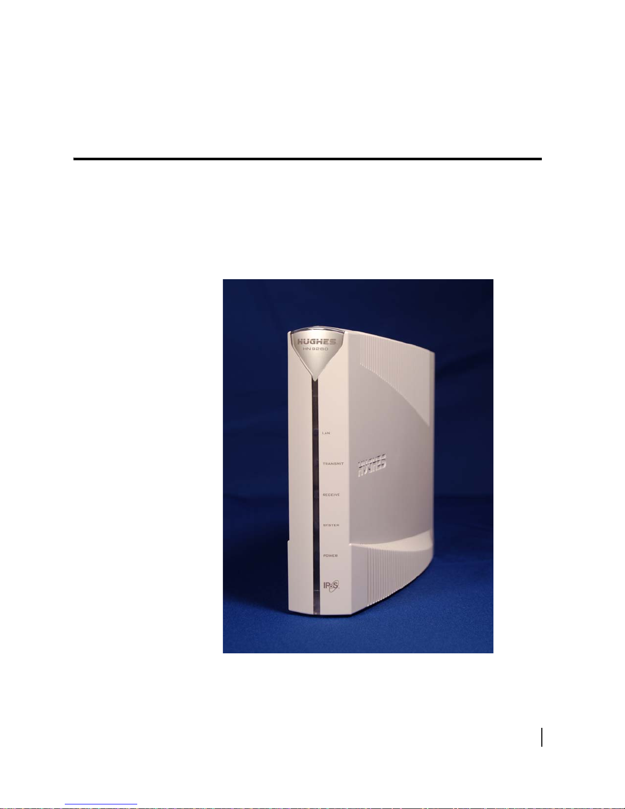
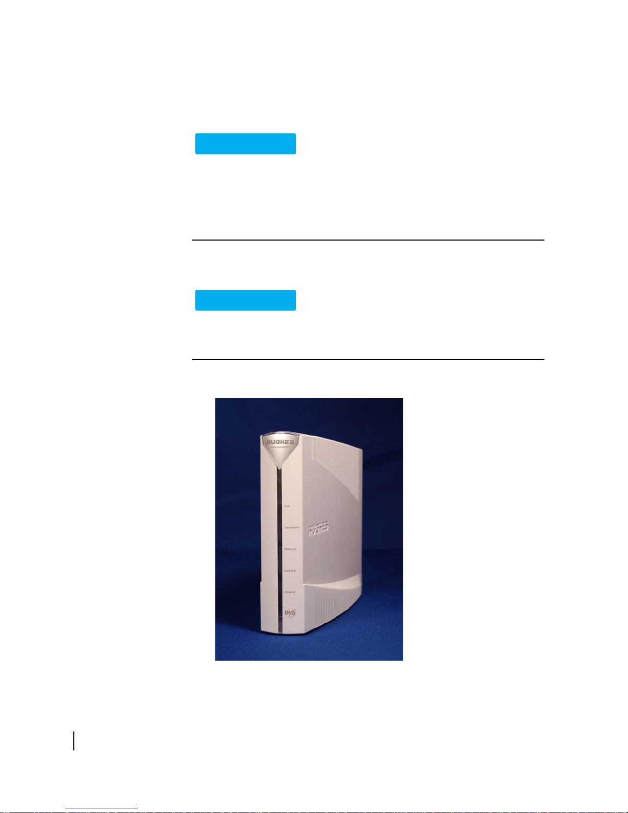
The HN9260 satellite modem connects to a satellite network to provide Internet or
intranet service or both to a host—typically a computer—or to multiple hosts on a
wired (Ethernet) or wireless LAN. The modem has an Ethernet port so it can be
connected to a computer or LAN.
The HN9260 can be used in either a Ka-band or Ku-band bent-pipe satellite network.
This ins
installations.
tallation guide includes instructions for both Ka-band and Ku-band
Figure 1: HN9260 satellite modem
Chapter 1 • Satellite modem overview
1039434-0001 Revision A
9

Terminology
In this installation guide:
ellite modem and modem both refer to the HN9260 satellite modem.
• Sat
taller Support refers to organizations that provide assistance to professional
• Ins
installers of Hughes satellite equipment. If you do not know who provides your
support, contact your program manager.
onyms are identified in Acronyms used in this guide on page 115.
• Acr
Scope of this installation guide
This installation guide explains how to install, commission, activate, and
troubleshoot the HN9260 satellite modem. It also contains certain reference
information concerning operation of the satellite modem, such as troubleshooting
information.
Audience
This guide is intended to be used by professional installers. It may also be useful for:
rainers who train installers
• T
• Call cen
ter operators who respond to customers’ calls
Satellite modem specifications
Table 1: Specifications for the HN9260 satellite modem
Weight 1.6 lb (0.73 kg)
Height 8.0 inches (20.3 cm)
Width 1.6 inches (4.1 cm); 2.4 inche
base
Depth 9.0 inches (22.9 cm)
Operating temperature range 41
Operating humidity range 5% to 90% non-condensing
Altitude Up to 15,000 ft (4,572 m)
Cooling method Convection
Protocol support TCP/IP (Transmission Control Protocol /
Supported frequency ranges Ka-band or Ku-band
Network interface ports RJ-45 Ethernet LAN port supporting
Power supplies and power requirements See
°F to 104 °F (5 °C to 40 °C)
Above 5,000 ft (1,524 m) altitude, the
ximum temperature is reduced by 1
ma
per 1,000 ft (305 m).
In
ternet Protocol) protocol suite
0BaseT or 100BaseT operation
1
Power supply information on
page 15.
s (6.1 cm) at
°C
10
Chapter 1 • Satellite modem overview
1039434-0001 Revision A
Chapter 2
Preparing for installation
This section describes preparations for installing the satellite modem and includes
information you should know before you begin. Review this information before you
install the satellite modem, antenna assembly, antenna mount, or IFL cables. Refer
also to Installation summary.
To install the satellite modem, you need the Ins
contains installation parameters and other installation information specific to your
installation site. Print the (Installation Reference Sheet for your installation site from
your installation support web site.
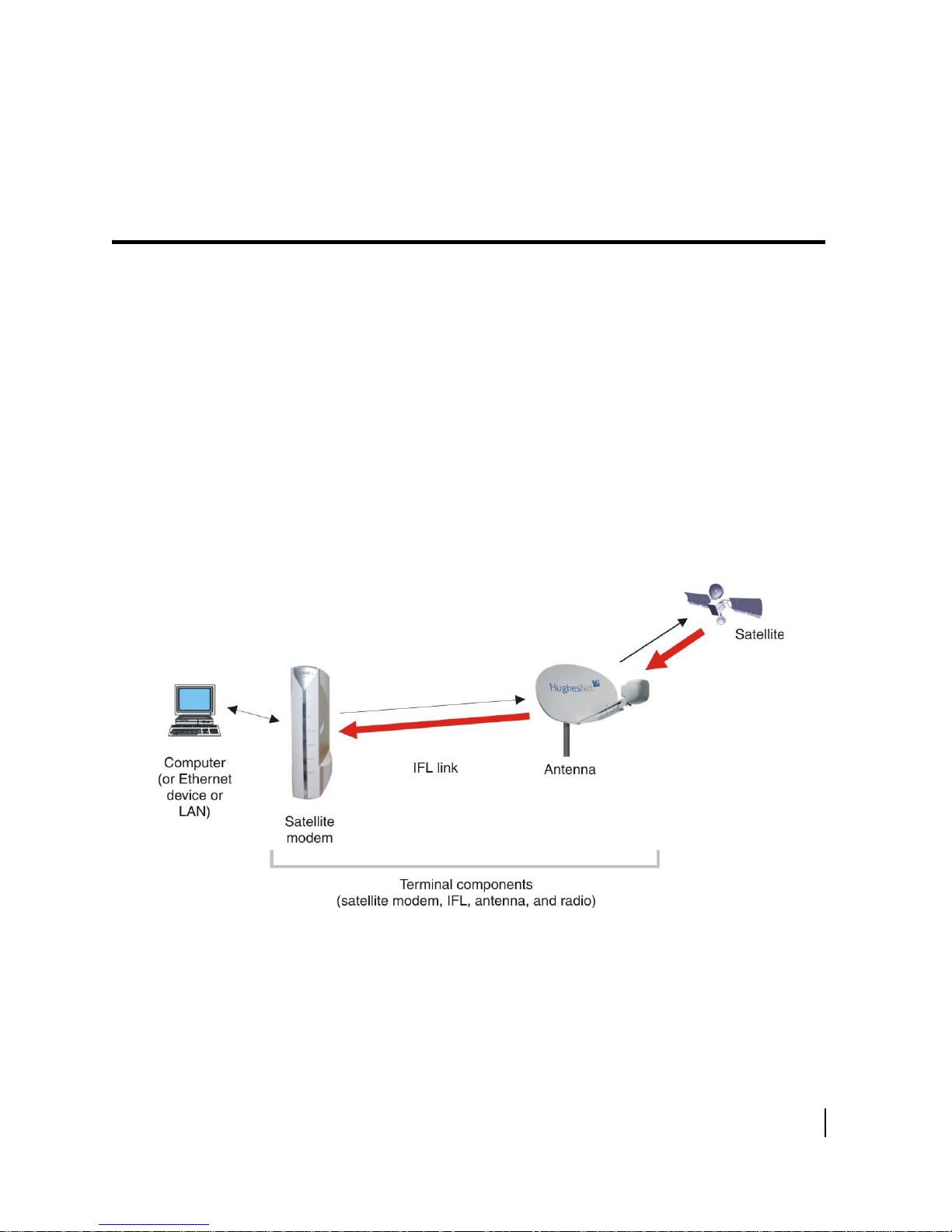
Installation summary
This guide explains how to install the HN9260 satellite modem. It includes limited
information about other satellite terminal components. The satellite modem is the
small indoor unit. The satellite terminal includes the satellite modem and the
antenna, radio assembly, and IFL cables, as shown in Figure 2.
tallation Reference Sheet, which
Figure 2: Satellite modem and related terminal components
This summary focuses on installation of the satellite modem, but also includes some
information on related tasks such as antenna installation and pointing. The tasks
listed below are the main installation tasks, but these are not all of the installation
tasks.
Chapter 2 • Preparing for installation
1039434-0001 Revision A
11

Complete all steps in the order they are presented in this installation guide unless
you have a specific reason for doing them in a different order. In any case, make sure
all steps are completed. You must install the antenna before the satellite modem can
be commissioned. Then you point the antenna as part of the modem commissioning
procedure.
Details for the satellite modem installation tasks are included in later chapters in this
guide.
Preparing for the installation
• Make sure you have all items required for installation, including the Installation
Reference Sheet, all equipment to be installed, and required tools for the
outdoor equipment.
• Make sure the customer’s computer meets the requirements listed in Computer
and networking requirements on page 17.
• Conduct a site survey.
• Assemble and install the antenna and radio as instructed in the antenna
installation guide.
Installing the satellite modem
• Connect the transmit and receive cables.
• Connect the modem to the installer laptop.
• Connect the power supply.
• Power up the modem and observe the LEDs to verify normal operation.
Commissioning the modem and pointing the antenna
• Upload the sbc.cfg file (if you are instructed to upload it).
• Enter the antenna location and satellite and radio parameters.
• Point the antenna.
• Register the satellite modem.
Completing the installation
• Confirm that all files are current.
• Connect the modem to the customer’s computer.
12
Chapter 2 • Preparing for installation
1039434-0001 Revision A

Installation checklist
To help ensure a successful installation, pay careful attention to the items listed in
the checklist below as you install the satellite modem, antenna, and IFL cables.
IFL cables
For specific cable information see Table 3 on page 20.
Use only Hughes-approved cables.
Do not exceed maximum length for the ODU type (1 W or 2 W), cable
type, and cable part number.
Do not exceed the cable bend radius.
Properly terminate cables.
Connectors and connections
Use only connector types approved for cable type used. Check all
connections for tightness.
Outdoors:
Make sure F connectors connected to the radio assembly are tightened
to 20 inch-lb torque.
Carefully follow waterproofing procedures, using dielectric grease and
Hughes-approved weatherproof tape.
Power source
Check AC power outlet for correct wiring
Before connecting the modem power supply to the AC power source
(using a surge protector), use an AC outlet tester to verify that the outlet
is wired correctly. Wiring problems may include:
• Hot and neutral wires reversed
eutral and ground wires reversed
• N
pen ground (incomplete connection)
• O
pen neutral
• O
If the outlet is wired improperly, notify the customer you are not permitted to
c
onnect the system to a faulty outlet. Do not proceed with installation until a
properly wired outlet is provided.
Chapter 2 • Preparing for installation
1039434-0001 Revision A
13

Check neutral-ground (N-G) voltage
With a digital multimeter set to AC voltage, measure the voltage
between neutral and ground at the AC power outlet. If the N-G voltage
measures 2 VAC or greater, please advise the customer to have an
electrician evaluate the electrical power outlet. N-G voltages may have a
negative impact on the performance of electronic equipment.
Grounding (modem, antenna, radio, and IFL)
Adhere to Hughes grounding requirements.
Use only approved ground wires, ground blocks, lugs, and clamps.
For detailed information refer to the appropriate FSB, as listed in Table 3 on page 20.
Items required for installation
To install the HN9260 satellite modem, you need:
260 satellite modem
• HN9
ower supply (provided in the shipping carton)
• P
ge protector (recommended), provided by the customer
• Sur
t-5 Ethernet cable
• Ca
sbc.cfg file (if you are instructed to upload it)
•
tallation Reference Sheet (provided to the installer)
• Ins
Welcome to HughesNet Quick Start Guide (10
38043-0001) (to give to the customer)
14
Notes
sbc.cfg file - If needed, you can download the most current sbc.cfg file from
your installation support web site.
SAN and PIN Customers who purchased their system from a Hughes retail channel in the United
States or Canada receive an order confirmation e-mail containing their site account
number (SAN) and personal identification number (PIN).
DC/DC power supply - If th
supply. See Table 2 on page 16. The installer must provide the wire required to
assemble the DC input power cable.
Chapter 2 • Preparing for installation
1039434-0001 Revision A
Identification numbers are required to register the satellite modem.
e site has a DC power source, it requires a DC/DC power
Additional equipment
• Antenna
• Hughe
• IFL c
s antenna pointing tool (DAPT for Ka-band, DAPT or OPI for Ku-band)
ables, cable connectors, and ground blocks
For more information on these items, see Related components on
No tools are required to install the modem. For tools needed to install the antenna
t and antenna and point the antenna, see:
moun
tenna Site Preparation and Mount Installation Guide (1035678-0001)
• An
• The ins
tallation guide for the antenna model you are installing
Conducting a site survey
Survey the customer site to confirm that the location meets the requirements for
installation of the satellite modem. For complete site survey information, including
site requirements, see the Antenna Site Preparation and Mount Installation Guide
(1035678-0001).
The key site survey tasks related to installation of the satellite modem are:
1. Make sure there is an unobstructed line of sight
Installation Reference Sheet.
2. Review the Installation Reference Sheet for site-specific instructions.
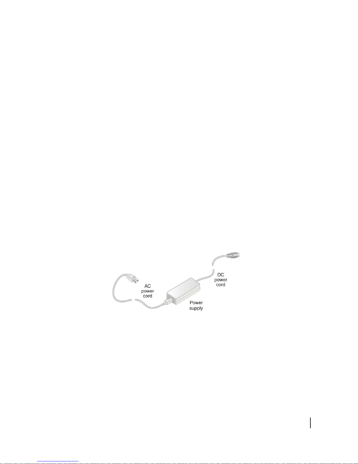
Power supply information
See also Connecting the power supply on page 24.
The power supply is included in the satellite modem shipping carton.
page 18.
to the satellite specified on the
Figure 3: AC power supply for the HN9260 satellite modem
Chapter 2 • Preparing for installation
1039434-0001 Revision A
15
Before proceeding, make sure you have the correct power supply. Check the part
NOTICE
CAUTION
number on the power supply and refer to Figure 3.
• Always use the power supply provided with the satellite modem. The
modem’s performance may suffer if the wrong power supply is used.
• Connect the AC/DC power supply to a three-wire, grounded outlet with an
input of 110/240 VAC. A suitable surge protector is recommended to protect
the satellite modem from possible damage due to power surges.
lways connect the DC power cord to the HN9260 rear panel before
• A
applying power to the power supply. If you apply power to the power
supply and then connect the DC power cord, the satellite modem may not
perform properly and could be damaged.
serve the power standards and requirements of the country where it is
• Ob
installed.
If there is any reason to remove power from the satellite modem, always unplug
the AC power cord from the power source (power outlet, power strip, or surge
protector). Do not remove the DC power cord from the modem’s rear panel.
Doing so could result in an electrical shock or damage the modem.
When you re-apply power to the modem, plug the AC power cord into the
power source.
16
Table 2: Power supply specifications for the HN9260 satellite modem
Power supply type Electrical requirements
AC/DC (64 W) Input line voltage:
90 to 264 VAC, 2 A maximum
Input line frequency:
50 to 60 Hz AC
Rated power consumption: 64 W
Chapter 2 • Preparing for installation
1039434-0001 Revision A
Table 2: Power supply specifications for the HN9260 satellite modem (Continued)
Power supply type Electrical requirements
AC/DC (80 W) Input line voltage:
90 to 264 VAC, 2 A maximum
Input line frequency:
50 to 60 Hz AC
Rated power consumption: 80 W
DC/DC (65 W) Input line voltage:
12 to 24 VDC, 10 A maximum
Rated power consumption: 65 W
All listed power supplies may be used with a 1 W or 2 W
Ka-band or Ku-band radio. All have a detachable power cord.
Computer and networking requirements
This section lists the requirements for the computer or other device, network, and
browser to be used with the satellite modem.
Computer requirements
The HN9260 satellite modem can be used with any device that supports IP and has a
10/100BaseT Ethernet LAN port. Typically, the modem is connected to a customer’s
computer. However, the HN9260 is self-hosted; it does not require a computer for
any of its functions.
Requirements for the computer to be used with the satellite modem are the same
for the laptop computer you use to install the modem and the customer’s computer
that will be connected to the modem. In either case, the computer should meet the
minimum requirements specified by the computer operating system manufacturer
and the following networking and browser requirements.
Make sure the installer laptop is configured to support DHCP.
Note: The satellite modem can be used with a Mac computer that meets these
requirements, but Mac computers are not supported as a tool for installing
the satellite modem.
Networking and Internet browser requirements
• Ethernet port
• Ethernet NIC installed on at least one computer, 10/100 BaseT
• Ethernet cable (provided)
• A web browser such as Internet Explorer with proxy settings disabled
Connecting a network - If the customer wants to connect a network to the satellite
modem, this requires an Ethernet hub or other such device. The customer must
supply and configure the hub and cables. Required IP address information is obtained
during commissioning.
Chapter 2 • Preparing for installation
1039434-0001 Revision A
17

Static IP address - The computer can be configured to use a static IP address if the
CAUTION
CAUTION
NOTICE
HughesNet service plan provides for one or more static IP addresses. If the computer
is configured to use a specific static IP address, disable DHCP.
Do not connect the power supply to the satellite modem, or connect the power
supply to a power source until you are instructed to do so.
Related components
The satellite modem is the indoor component of the satellite terminal. The terminal
also includes the (outdoor) antenna and IFL cables. This section presents information
on the outdoor components and other related equipment. For additional
information, see the applicable documents listed in Table 3 on page 20.
Antenna
You must assemble and install the antenna before you install the satellite modem.
You point the antenna as part of the modem commissioning process.
Only a trained professional installer should install the outdoor antenna
assembly. In the United States, the Federal Communications Commission (FCC)
requires professional installation and service of the antenna assembly because
it transmits radio frequency (RF) energy.
The HN9260 satellite modem can be used with a 0.74 m, 0.98 m, 1.2 m, or 1.8 m
two-way satellite antenna. The antenna assembly is shipped in a separate box.
The main source of information on the ant
Each antenna model has its own installation guide. If you do not have the antenna
installation guide, find the required antenna model on the Installation Reference
Sheet; then locate the installation guide for that model on your installation support
web site.
When you install the antenna assembly, read and follow all safety alerts and
instructions in the antenna installation guide and in the Antenna Site
Preparation and Mount Installation Guide (1035678-0001).
enna is the antenna installation guide.
18
Chapter 2 • Preparing for installation
1039434-0001 Revision A
IFL Cables
WARNING
Before you can install the satellite modem, you must route the coaxial IFL cables
between the indoor satellite modem location and the antenna. Then you connect the
modem and the antenna by connecting the IFL cable to both components.
The routing path of the IFL cables between the modem and the antenna depends on
the bui
Antenna Site Preparation and Mount Installation Guide (1035678-0001).
Requirements for cables, connectors, and ground blocks
You must use approved cable types and connectors to connect the modem to the
outdoor satellite antenna. For grounding, you must use approved ground blocks and
grounding connectors. For detailed specifications and information on these
components, see the documents listed in Table 3 on page 20.
The coaxial IFL cables and the ground block to which they are connected must meet
the gr
lding configuration. Guidelines for installing IFL cables are included in the
ounding requirements specified in the following warning:
You must comply with applicable local codes and the grounding requirements in
Field Service Bulletin (FSB), HNS Broadband Requirements for RG-6 and RG-11
IFL Cable Connectors, Ground Blocks, and Ground Block Location
(FSB_050518_01). Improper grounding can result in electric shock injury,
property damage, and/or poor modem performance.
Labeling the IFL cables
Label the receive and transmit IFL cables at the outdoor point-of-entry and at the
indoor location where the satellite modem is installed as follows:
p a piece of red electrical tape around the receive cable, and mark SAT IN on
• Wra
the tape.
rap a piece of blue electrical tape around the transmit cable, and mark SAT
• W
OUT on the tape.
Hub or similar network device
If the satellite modem is to be connected to a network, an Ethernet hub, modem,
wireless base station, or other similar device is required. The customer must supply
and configure the network device, including required cables, according to the device
manufacturer’s documentation. Required IP address information is obtained during
modem commissioning.
Chapter 2 • Preparing for installation
1039434-0001 Revision A
19

Instructions for related components
This installation guide covers only installation of the satellite modem. For installation
instructions for other components, see Table 3. You can view or download these
documents at https://dwayinstalls.hns.com/ (click
installation support web site. If you cannot log in, contact Installer Support-or
contact your program manager for access to these documents.
Table 3: Related installation documents
Component or topic Where to find instructions
Installer Login Click Here! or your
Safety (all components)
Site survey
Site preparation
Antenna mounts
IFL
IFL cables (specifications, approved types,
ximum lengths)
ma
IFL cable connectors
Grounding
Ground blocks
Antenna, antenna pointing
Radio assembly
Antenna Site Preparation and Mount
tallation Guide (1035678-0001).
Ins
For Ku-band installations: Field Service
Bulletin (FSB), IFL Cable, Approved List
(with lengths) for DW7x00, DW60xx, and
DW40xx Domestic Installations
(FSB_60316_01).
(IFL cable specifications in this FSB apply to
N9260 Ka-band and Ku-band
H
installations.)
Field Service Bulletin (FSB), HNS
band Requirements for RG-6 and
Broad
RG-11 IFL Cable Connectors, Ground
Blocks, and Ground Block Location
(FSB_050518_01).
See the antenna installation guide for the
ic antenna model you are installing.
specif
For Ka-band antennas, see also the
a-Band Antenna Pointing Guide for
K
Bent-Pipe Satellite Networks
(1038764-0001).
Antenna pointing for Ku-band antennas is
overed in the antenna installation guide.
c
20
1039434-0001 Revision A
Chapter 2 • Preparing for installation

Installing the satellite modem
Installation of the HN9260 satellite modem consists of physical installation, followed
by commissioning and registration. These processes prepare the modem for
operation on the satellite network. Installation tasks include:
• Physical installation and power-up
• Entering parameters required for commissioning
• Commissioning, including antenna pointing
The installation software is factory pre-installed in the satellite modem. If necessary,
this software is automatically updated as part of the installation process. You access
the installation software through a browser on your installer computer to perform
tasks such as entering required parameters.
Prerequisites for installing the modem
The following are required before you can install, commission, and register the
satellite modem:
• The antenna and radio assembly must be installed, as instructed in the antenna
installation guide. (However, you point the antenna as part of the modem
commissioning process, which is explained later in this installation guide.)
• The IFL cables must be installed and connected to the satellite modem and to the
radio assembly (LNB and transmitter).
Chapter 3
See also Items required for installation on page 14 and Related components on
page 18.
Selecting the modem installation location
Select a location for the satellite modem that will accommodate all required cable
connections, including connection to the power source.
Chapter 3 • Installing the satellite modem
1039434-0001 Revision A
21
Ventilation and heat sources
NOTICE
NOTICE
Make sure the installation location meets the following requirements concerning
ventilation and heat sources.
• Do not block any of the modem’s ventilation openings.
• Leave 6 inches of space around the top and sides of the modem to ensure
adequate ventilation and prevent overheating.
o not place the modem near a heat source such as direct sunlight, a
• D
radiator, heat register or vent, oven, stove, amplifier, or other apparatus
that produces heat.
Modem operating position
Install and operate the HN9260 modem only in the upright vertical position as
shown in
overheating, and malfunction.
Figure 4. Any other position could result in insufficient ventilation,
Figure 4: HN9260 in vertical position
22
Chapter 3 • Installing the satellite modem
1039434-0001 Revision A
Connecting the transmit and receive cables
RESCUE
SWITCH
SAT.
IN
SAT.
OUT
DC IN
LAN
Modem
rear panel
Transmit
cable
Receive
cable
SAT. IN connector
SAT. OUT connector
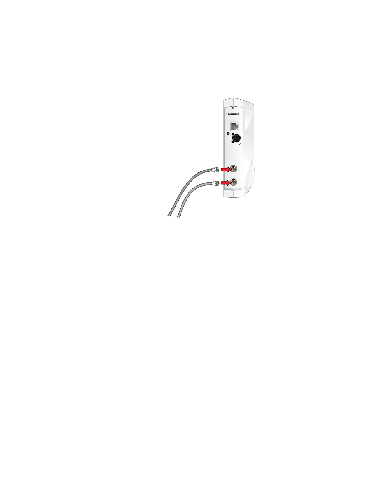
Connect the transmit and receive IFL cables to the satellite modem.
1. Connect the transmit and receive cables to the connectors on the rear panel of
the modem
as shown in Figure 5.
Figure 5: Connecting the transmit and receive cables to the modem
Note: The satellite modem may operate correctly when first installed even if the
transmit and receive cable connectors are not adequately tightened.
However, problems could develop later. Therefore, successful modem
operation is not an indication that the cables are adequately tightened.
2. Make sure neither the satellite modem nor the customer’s computer are
onnected to an Ethernet router or switch.
c
Note: Do not c
onnect any device to the satellite modem at this time except the
installer laptop computer. Ethernet devices may only be connected to the
modem after it is installed and commissioned.
Connecting the installer laptop to the modem
For this task you need an Ethernet cable.
To access the satellite modem so you can perform the required installation
ocedures, you connect your installer laptop computer to the modem. After the
pr
modem is installed and registered with the satellite network, you connect the
modem to the customer’s computer or other device. During modem installation the
installer laptop computer must be directly connected to the modem without any
intervening connection.
Chapter 3 • Installing the satellite modem
1039434-0001 Revision A
23

1. Use an Ethernet cable to connect your laptop computer directly to the modem’s
NOTICE
LAN port, as shown in Figure 6.
Do not c
switch.
onnect the installer laptop to the modem through an Ethernet router or
Figure 6: Connecting the installer laptop computer to the modem
2. Make sure that neither the satellite modem nor the customer’s computer are
connected to an Ethernet router or switch.
3. If you are running firewall software on the laptop computer, disable it until you
omplete installation of the modem.
c
The LAN LED on the front of the modem should now be on.
Connecting the power supply
Follow the instructions in Connecting an AC/DC power supply on page 24 or
Connecting and assembling a DC/DC power supply on p
Connecting an AC/DC power supply
The following apply to the AC/DC power supplies:
• The input must be 120-240 VAC.
suitable surge protector is recommended to protect the modem from
• A
possible damage due to power surges.
The customer provides the surge protector. If a surge protector or power strip is not
pr
esent, use a wall outlet or other power source.
age 26.
24
Chapter 3 • Installing the satellite modem
1039434-0001 Revision A

In some countries, the modem may use a replacement AC power cord. Different
NOTICE
countries have different standards and requirements that must be observed.
Before connecting the modem power supply to the AC power source (using a surge
pr
otector), use an AC outlet tester to verify that the power outlet is wired correctly.
Wiring problems may include:
• Hot and neutr
• Neutr
• O
• O
If the outlet is wired improperly, notify the customer that you are not permitted to
onnect the system to a faulty outlet. Do not proceed with the installation until a
c
properly wired outlet is provided.
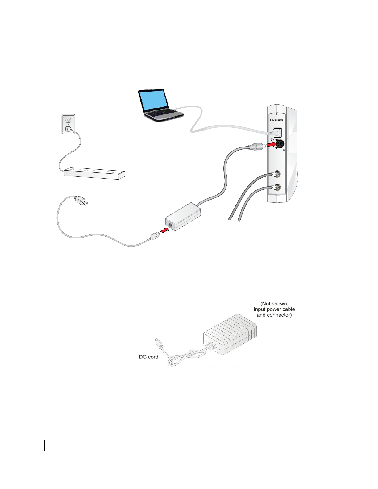
Connect the power supply as follows:
1. Check Power supply information on p
2. Connect the DC power cord to the DC IN port on the modem, as shown in
3. Connect the AC power cord to the power supply.
al and ground wires reversed
pen ground (incomplete connection)
pen neutral
power supply.
Figure 7.
If you apply power to the power supply and then connect the
DC power cord, the satellite modem may not perform properly and could be
damaged.
al wires reversed
age 15 to make sure you have the correct
Chapter 3 • Installing the satellite modem
1039434-0001 Revision A
25
Do not connect the AC power cord to the surge protector at this time. Wait until you
RESCUE
SWITCH
SAT.
IN
SAT.
OUT
DC IN
LAN
Powe r
supply
Surge protector
AC power cord
AC
power
outlet
DC IN
power
connector
Do not connect the power
supply to the surge protector
until you are ready to observe
the LEDs for proper operation.
DC
power
cord
are ready to observe the modem’s LEDs upon power-up, as explained in Powering up
the modem on
page 27 and LEDS on power-up on page 27.
Chapter 3 • Installing the satellite modem
26
1039434-0001 Revision A
Figure 7: Connecting an AC power supply
Connecting and assembling a DC/DC power supply
Figure 8 shows the DC/DC power supply used with the HN9260 modem.
Figure 8: DC/DC power supply
Connect and assemble the DC/DC power supply as follows:
1. Connect the DC power cord to the DC IN port on the modem.

Note: The input cable kit is included in the power supply kit. The cable kit contains
an input power connector, connector pins, and a wiring diagram; it does not
include wire.
2. Assemble the input power cable according to the wiring diagram included in the
cable kit.
3. Connect the input power cable to the DC power source, but do not connect the
input power connector to the power supply at this time.
Do not connect the input power connector to the power supply until you are
ready to observe the modem’s LEDs upon power-up, as explained in
power-up.
Powering up the modem
Check Power supply information on page 15 to make sure you have the correct
power supply.
Follow these instructions to power up the modem for the first time.
AC/DC power supply
Prerequisites:
• The power outlet has been tested, as described in Connecting an AC/DC power
supply on page 24.
• According to previous instructions, the DC power cord is connected to the
modem’s rear panel, and the AC power cord is connected to the power supply.
LEDS on
1. Connect the AC power cord into the surge protector or wall outlet.
2. Observe the LEDs for proper operation. See LEDS on power-up.
DC/DC power supply
Prerequisites: The DC power cord is connected to the modem’s rear panel, and the
input power cable is assembled and connected to the DC power source.
1. Connect the input cable connector to the power supply.
2. Observe the LEDs for proper operation. See LEDS on power-up.
LEDS on power-up
As the modem powers up, observe the front panel LEDs to make sure the modem is
working properly. When power is applied to the modem or after a modem reset, the
LEDs light up in the following order, indicating normal power-up:
1. All LEDs light up for ½ sec while the modem performs a self-test.
2. The Power LED lights up and remains on, indicating the modem is powered up.
3. The Power LED and System LED light up for about 5 to 10 sec while the modem
loads and prepares applications.
4. If the modem LAN port is connected to a network device, the LAN LED lights up
within 30 sec, indicating that LAN connectivity is detected.
5. The Power LED blinks, indicating that the modem is not commissioned.
Chapter 3 • Installing the satellite modem
1039434-0001 Revision A
27

28
Chapter 3 • Installing the satellite modem
1039434-0001 Revision A

Chapter 4
Commissioning the satellite modem
Commissioning refers to a series of procedures to make the newly installed satellite
modem ready for network operation and register the modem with the service
provider’s network.
Commissioning methods
Two methods are available for commissioning the HN9260 satellite modem:
• Satellite-based commissioning on page 29
• Manual commissioning on page 58
Satellite-based commissioning is the preferred commissioning method. Use the
manual commissioning method only if satellite-based commissioning is not available
and if you are instructed to do so by the service provider.
Satellite-based commissioning
Satellite-based commissioning (SBC) is the preferred commissioning method. Using
SBC, you use a web-based interface on the satellite modem to:
• Obtain an IP address from the modem
• Verify the Ethernet connection (ping test)
• Upload the sbc.cfg file to the modem
• Enter commissioning parameters
• Point the antenna
• Register the modem
The modem contains an SBC configuration file (sbc.cfg) that contains satellite
information for SBC and the auto-commissioning server (ACS) used during
commissioning. Occasionally, new satellites are activated to support broadband
service. As a result, you may be required to upload an
prior to installation or manually enter satellite parameters during modem
installation.
If a new sbc.cfg file is available you are instructed to download the sbc.cfg file
from an installation support web site. You must save the
laptop computer prior to commissioning so you can upload it to the modem.
If a new satellite is activated but a new sbc.cfg file is not available, the new
satellite parameters are distributed to you in a technical update email or other
communication. In this case you must manually enter the new satellite parameters.
Chapter 4 • Commissioning the satellite modem
sbc.cfg file to the modem
sbc.cfg file the installer
1039434-0001 Revision A
29
Note: If the service provider has provided you with an sbc.cfg file, you must
complete the procedures in Uploading the sbc.cfg file to the satellite modem
on page 32 to upload the file to the modem.
If you need troubleshooting information concerning satellite-based commissioning,
see the satellite modem’s online Help. Access this information through the System
Control Center
Help link (Help > Frequently Asked Questions).
Obtaining an IP address from the satellite modem
1. Make sure the installer laptop is configured to support DHCP.
2. Verify that the installer laptop is connected to the modem with an Ethernet
ble.
ca
3. Open a command prompt or window on the installer laptop.
4. Type
5. Press
6. Type
7. Press
ipconfig /release.
Enter.
ipconfig /renew.
Enter.
Note: T
o view all IP configuration commands, open a command prompt window,
ipconfig /help, and press Enter.
type
If the modem does not assign IP address 192.16
the installer laptop to obtain the IP address.
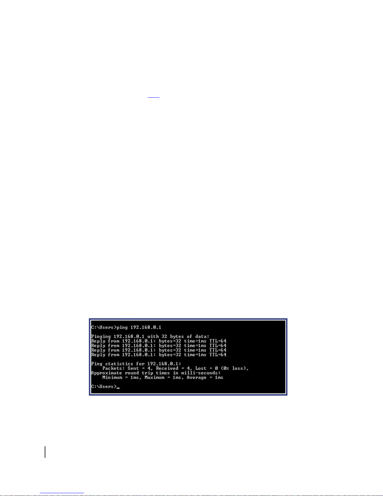
Verifying the Ethernet connection
Execute a ping test to verify that the Ethernet connection between the satellite
modem and the installer laptop is active:
1. Open a command prompt or window on the installer laptop.
2. Type
3. Press
ping 192.168.0.1.
Enter.
If the ping is successful, the ping results show that all sent packets were
r
eceived.
8.0.2 to the installer laptop, restart
30
Chapter 4 • Commissioning the satellite modem
1039434-0001 Revision A
Figure 9: Successful ping test
 Loading...