

Hughes HN9200 Installation Manual

HN9200 Satellite Modem
Installation Guide
1038622-0001
Revision B
March 2, 2011

Copyright © 2010-2011 Hughes Network Systems, LLC
All rights reserved. This publication and its contents are propr ietary to Hughes Network Systems, LLC.
No part of this publication may be reproduced in any form or by any means without the written
permission of Hughes Network Systems, LLC, 11717 Exploration Lane, Germantown, Maryland 20876.
Hughes Network Systems, LLC has made every effort to ensure the correctness and complet
the mater
herein. The information in this document is subject to change without notice. Hughes Network Systems,
LLC makes no warranty of any kind with regard to this material, including, but not limited to, the implied
warranties of merchantability and fitness for a particular purpose.
Hughes, Hughes Network Systems, and HughesNet are trademarks of Hughes Network Systems, LLC.
All other trademarks are the property of their respective owners.
ial in this document. Hughes Network Systems, LLC shall not be liable for errors contained
eness of
Trademarks

Contents
Understanding safety alert messages.................................................................................xi
Chapter 1: Satellite modem overview............................................................1
Chapter 2: Preparing for installation.............................................................3
Messages concerning personal injury.....................................................................................................xi
Messages concerning property damage...................................................................................................xi
Safety symbols........................................................................................................................................xi
Scope of this installation guide................................................................................................................2
Satellite modem specications.................................................................................................................2
Installation summary................................................................................................................................4
Installation checklist.................................................................................................................................5
Items required for installation..................................................................................................................6
Conducting a site survey..........................................................................................................................7
Power supply information........................................................................................................................7
Computer and networking requirements..................................................................................................8
Computer requirements................................................................................................................8
Networking and Internet browser requirements...........................................................................9
Related components.................................................................................................................................9
Antenna........................................................................................................................................9
IFL cables...................................................................................................................................10
Requirements for cables, connectors, and ground blocks..............................................10
Labeling the IFL cables..................................................................................................10
Hub or similar network device...................................................................................................10
Instructions for related components...........................................................................................11
Chapter 3: Installing the satellite modem....................................................13
Prerequisites for installing the modem...................................................................................................14
Selecting the modem installation location..............................................................................................14
Ventilation and heat sources.......................................................................................................14
Modem operating position.....................................................................................................................14
Connecting the transmit and receive cables...........................................................................................15
Connecting the installer laptop to the modem........................................................................................16
Connecting the power supply.................................................................................................................17
Connecting an AC/DC power supply.........................................................................................17
Connecting and assembling a DC/DC power supply.................................................................18
Powering up the modem.........................................................................................................................19
AC/DC power supply.................................................................................................................19
DC/DC power supply.................................................................................................................19
HN9200 Satellite Modem Installation Guide
1038622-0001 Revision B
iii

Contents
LEDS on power-up.................................................................................................................................19
Chapter 4: Commissioning the satellite modem.........................................21
Satellite-based commissioning...............................................................................................................22
Obtaining an IP address from the satellite modem.....................................................................22
Verifying the Ethernet connection..............................................................................................23
Uploading the sbc.cfg le to the satellite modem......................................................................24
Entering commissioning parameters..........................................................................................26
Entering the antenna location.........................................................................................27
Entering the antenna location (manual entry)................................................................28
Entering satellite parameters..........................................................................................29
Entering satellite parameters (manual entry)..................................................................31
Entering radio parameters..............................................................................................33
Receive antenna pointing – Ka-band..........................................................................................37
Receive antenna pointing – Ku-band.........................................................................................41
Transmit antenna pointing – Ku-band........................................................................................41
Registering the satellite modem.................................................................................................43
Registering in the United States or Canada....................................................................45
Registering outside the United States and Canada.........................................................47
Completing registration..................................................................................................48
Manual commissioning .........................................................................................................................50
Entering parameters—manual commissioning..........................................................................51
Manually accessing the antenna pointing screens......................................................................53
Software download—manual commissioning............................................................................53
Chapter 5: Completing the installation........................................................55
Conrming that the satellite modem’s les are up to date.....................................................................56
Connecting the satellite modem to the customer’s computer.................................................................57
Verify that the customer can browse the Internet...................................................................................57
Printing the System Information page....................................................................................................58
Creating a shortcut to the System Control Center..................................................................................58
Installation complete..............................................................................................................................59
Chapter 6: System Control Center...............................................................61
Accessing the System Control Center....................................................................................................62
System Control Center home page.........................................................................................................62
Text links....................................................................................................................................63
Common features on System Control Center screens............................................................................64
Button links................................................................................................................................65
System Status button......................................................................................................66
IPSec icon...........................................................................................................66
Links in the left panel.................................................................................................................67
Small icon on System Control Center screens (Advanced Pages).............................................67
iv
HN9200 Satellite Modem Installation Guide
1038622-0001 Revision B

Contents
Status and information screens...................................................................................................68
Red ag indicator...........................................................................................................68
Features a customer may not see............................................................................................................69
System Status page.................................................................................................................................69
Reception Information page...................................................................................................................71
Examining receive status............................................................................................................72
Transmission Information page..............................................................................................................73
Examining transmit status..........................................................................................................73
System Information page........................................................................................................................74
Help page................................................................................................................................................76
System Control Center tools for troubleshooting...................................................................................77
Chapter 7: LEDs............................................................................................79
Front panel LEDs...................................................................................................................................80
LAN port LEDs......................................................................................................................................81
Using LEDs for troubleshooting............................................................................................................81
Chapter 8: Troubleshooting..........................................................................83
Important troubleshooting information..................................................................................................84
Troubleshooting reference diagram........................................................................................................84
Troubleshooting common problems.......................................................................................................85
Cannot access the Internet......................................................................................................................86
Conrming that the satellite modem is commissioned..............................................................87
Conrming the receive signal....................................................................................................88
Conrming the transmit signal...................................................................................................88
Conrming that TCP Acceleration is operational......................................................................89
Conrming that Web Acceleration is operational......................................................................90
Conrming NOC connectivity...................................................................................................91
Conrming NOC connectivity (Static IP Address)........................................................92
Conrming Internet connectivity...............................................................................................93
Checking the DNS setting..............................................................................................93
Checking for viruses and rewall issues....................................................................................94
Cannot access the System Control Center..............................................................................................94
Satellite modem connected directly to a computer....................................................................94
Satellite modem connected to an Ethernet device......................................................................94
Using the front panel LEDs for troubleshooting....................................................................................95
Power LED off and one or more LEDs ashing........................................................................96
All LEDs ashing.......................................................................................................................96
All LEDs off...............................................................................................................................96
Checking the Power LED...........................................................................................................97
Checking the LAN LED.............................................................................................................97
Problem with a connected device...........................................................................................................98
Transmit LED is off....................................................................................................................98
Receive LED is off.....................................................................................................................99
HN9200 Satellite Modem Installation Guide
1038622-0001 Revision B
v

Contents
System LED is off......................................................................................................................99
Using the LAN port LEDs for troubleshooting ...................................................................................100
Orange LED and the front panel LAN LED are both off.........................................................100
Orange LED is on but the front panel LAN LED is not...........................................................100
Troubleshooting other problems...........................................................................................................100
Slow speed or intermittent operation........................................................................................101
Viewing problem-related statistics.......................................................................................................101
Checking for possible AC outlet problems..........................................................................................102
Chapter 9: Advanced Pages........................................................................103
Accessing the Advanced Pages............................................................................................................104
Expanding and collapsing menus.........................................................................................................105
Opening the Installation sub-menu.......................................................................................................105
Appendix A: LNB selection reference........................................................107
Appendix B: Updating the modem software.............................................109
Extracting les.....................................................................................................................................109
Update instructions...............................................................................................................................109
Appendix C: Standards compliance...........................................................111
Safety – Operating conditions for Canada...........................................................................................111
Repairs in Canada.....................................................................................................................111
Electromagnetic interference (EMI).....................................................................................................112
FCC Part 15..............................................................................................................................112
Canada Class B warning...........................................................................................................112
R&TTE (EU)............................................................................................................................112
Electromagnetic compatibility (EMC).................................................................................................113
R&TTE (EU)............................................................................................................................113
IPoS......................................................................................................................................................113
Appendix D: Acronyms used in this guide................................................115
vi
HN9200 Satellite Modem Installation Guide
1038622-0001 Revision B

Table of Figures
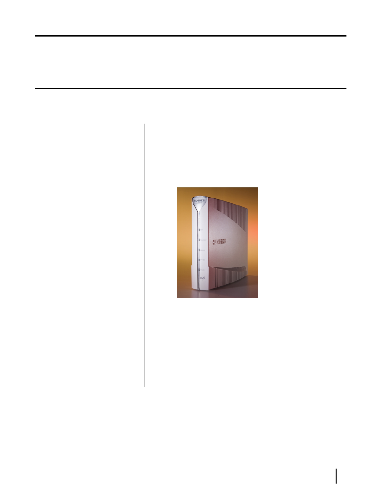
Figure 1: HN9200 satellite modem..................................................................................................................................1
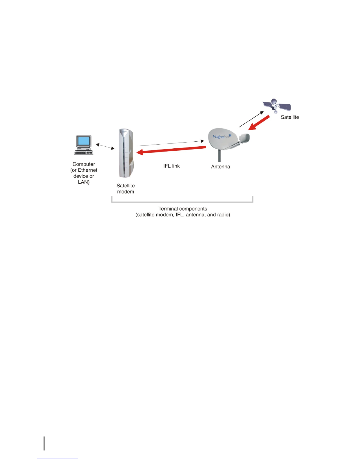
Figure 2: Satellite modem and related terminal components...........................................................................................4
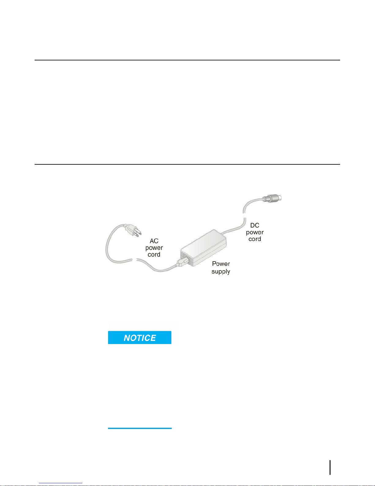
Figure 3: AC power supply for the HN9200 satellite modem.........................................................................................7
Figure 4: HN9200 in vertical position............................................................................................................................15
Figure 5: Connecting the transmit and receive cables to the modem.............................................................................15
Figure 6: Connecting the installer laptop computer to the modem................................................................................16
Figure 7: Connecting an AC power supply....................................................................................................................18
Figure 8: DC/DC power supply.....................................................................................................................................18
Figure 9: Successful ping test.........................................................................................................................................23
Figure 10: Failed ping test..............................................................................................................................................23
Figure 11: Satellite Setup menu.....................................................................................................................................25
Figure 12: Conguration File Upload screen.................................................................................................................26
Figure 13: Conrming the sbc.cfg le upload...............................................................................................................26
Figure 14: Satellite Setup menu.....................................................................................................................................27
Figure 15: Antenna Location screen..............................................................................................................................28
Figure 16: Verication of Antenna Location screen......................................................................................................28
Figure 17: Manual Entry of Antenna Location screen...................................................................................................29
Figure 18: Satellite Parameters screen...........................................................................................................................30
Figure 19: Verifying the satellite parameters screen......................................................................................................31
Figure 20: Satellite Parameters screen...........................................................................................................................32
Figure 21: Manual Entry of Satellite Parameters screen................................................................................................32
Figure 22: Receive LNB Selection screen—two variations...........................................................................................34
Figure 23: Verication of Receive LNB Parameters screen..........................................................................................35
Figure 24: Transmit Radio Parameters screen................................................................................................................35
Figure 25: Selecting the transmit radio by part number.................................................................................................36
Figure 26: Verication of Transmit Radio Parameters screen.......................................................................................37
Figure 27: Receive Antenna Pointing screen.................................................................................................................38
Figure 28: DAPT Antenna Pointing Status window......................................................................................................38
Figure 29: DAPT Antenna Pointing Status window – nal validation passed..............................................................39
Figure 30: KA Antenna Pointing Validation screen – nal validation passed...............................................................40
Figure 31: Receive pointing screen with signal quality window...................................................................................41
Figure 32: Initiating a manual cross-polarization test....................................................................................................42
Figure 33: Manual cross-polarization warning message................................................................................................43
Figure 34: Manual cross-polarization test results...........................................................................................................43
Figure 35: Selecting the registration server....................................................................................................................44
Figure 36: Registration in Progress screen.....................................................................................................................45
Figure 37: Redirect notication message.......................................................................................................................45
Figure 38: Installer notice and subscriber agreement screen.........................................................................................46
Figure 39: Entering SAN and PIN.................................................................................................................................47
Figure 40: Entering a site ID..........................................................................................................................................48
Figure 41: Registration Welcome screen........................................................................................................................49
HN9200 Satellite Modem Installation Guide
1038622-0001 Revision B
vii

Table of Figures
Figure 42: Registration screen with modem identication information........................................................................49
Figure 43: Registration complete – restarting the modem.............................................................................................50
Figure 44: Satellite Setup menu.....................................................................................................................................51
Figure 45: Manual Commissioning page.......................................................................................................................52
Figure 46: Antenna pointing screen...............................................................................................................................53
Figure 47: System Status page.......................................................................................................................................56
Figure 48: Connecting the HN9200 to the customer’s computer...................................................................................57
Figure 49: Icon used to create shortcut..........................................................................................................................59
Figure 50: System Control Center home page...............................................................................................................63
Figure 51: Common features on System Control Center screens..................................................................................64
Figure 52: System Control Center button links..............................................................................................................65
Figure 53: IPSec icon.....................................................................................................................................................66
Figure 54: Icon for accessing the Advanced Pages........................................................................................................67
Figure 55: Format of status and information screens.....................................................................................................68
Figure 56: Red ag problem indicator...........................................................................................................................69
Figure 57: System Status page.......................................................................................................................................70
Figure 58: Reception Information page..........................................................................................................................71
Figure 59: Finding additional Receive Status information............................................................................................72
Figure 60: List of all RxCodes.......................................................................................................................................72
Figure 61: Transmission Information page....................................................................................................................73
Figure 62: Finding additional Transmit Status information...........................................................................................74
Figure 63: List of TxCodes (not all codes are shown)...................................................................................................74
Figure 64: System Information page..............................................................................................................................75
Figure 65: Help page......................................................................................................................................................77
Figure 66: Front panel LEDs on the HN9200 modem...................................................................................................80
Figure 67: LAN port LEDs............................................................................................................................................81
Figure 68: Troubleshooting reference diagram..............................................................................................................85
Figure 69: Problem Troubleshooting page.....................................................................................................................86
Figure 70: System Info page..........................................................................................................................................87
Figure 71: Reception Info page......................................................................................................................................88
Figure 72: Transmission Info page.................................................................................................................................88
Figure 73: Conrming that TCP Acceleration is operational........................................................................................89
Figure 74: Connectivity Test – initial page....................................................................................................................91
Figure 75: Connectivity Test – results page...................................................................................................................92
Figure 76: Detailed Problem Statistics.........................................................................................................................101
Figure 77: Selecting a category of statistics.................................................................................................................102
Figure 78: Icon for accessing Advanced Pages (arrow)...............................................................................................104
Figure 79: Advanced Pages example showing the Advanced menu............................................................................104
Figure 80: Selection aid for Ka-band LNBs.................................................................................................................107
Figure 81: Selection aid for Ku-band LNBs................................................................................................................108
Figure 82: IPoS symbol................................................................................................................................................113
viii
HN9200 Satellite Modem Installation Guide
1038622-0001 Revision B

Table of Tables
Table 1: Specications for the HN9200 satellite modem.................................................................................................2
Table 2: Power supply specications for the HN9200 satellite modem..........................................................................8
Table 3: Related installation documents.........................................................................................................................11
Table 4: Button links on System Control Center screens...............................................................................................65
Table 5: System Status button colors.............................................................................................................................66
Table 6: System Status page parameters........................................................................................................................70
Table 7: Reception Information page parameters...........................................................................................................71
Table 8: Transmission Information page parameters.....................................................................................................73
Table 9: System Information page parameters – HN9200 Info section.........................................................................75
Table 10: Front panel LED indications..........................................................................................................................80
Table 11: HN9200 standards compliance.....................................................................................................................111
HN9200 Satellite Modem Installation Guide
1038622-0001 Revision B
ix

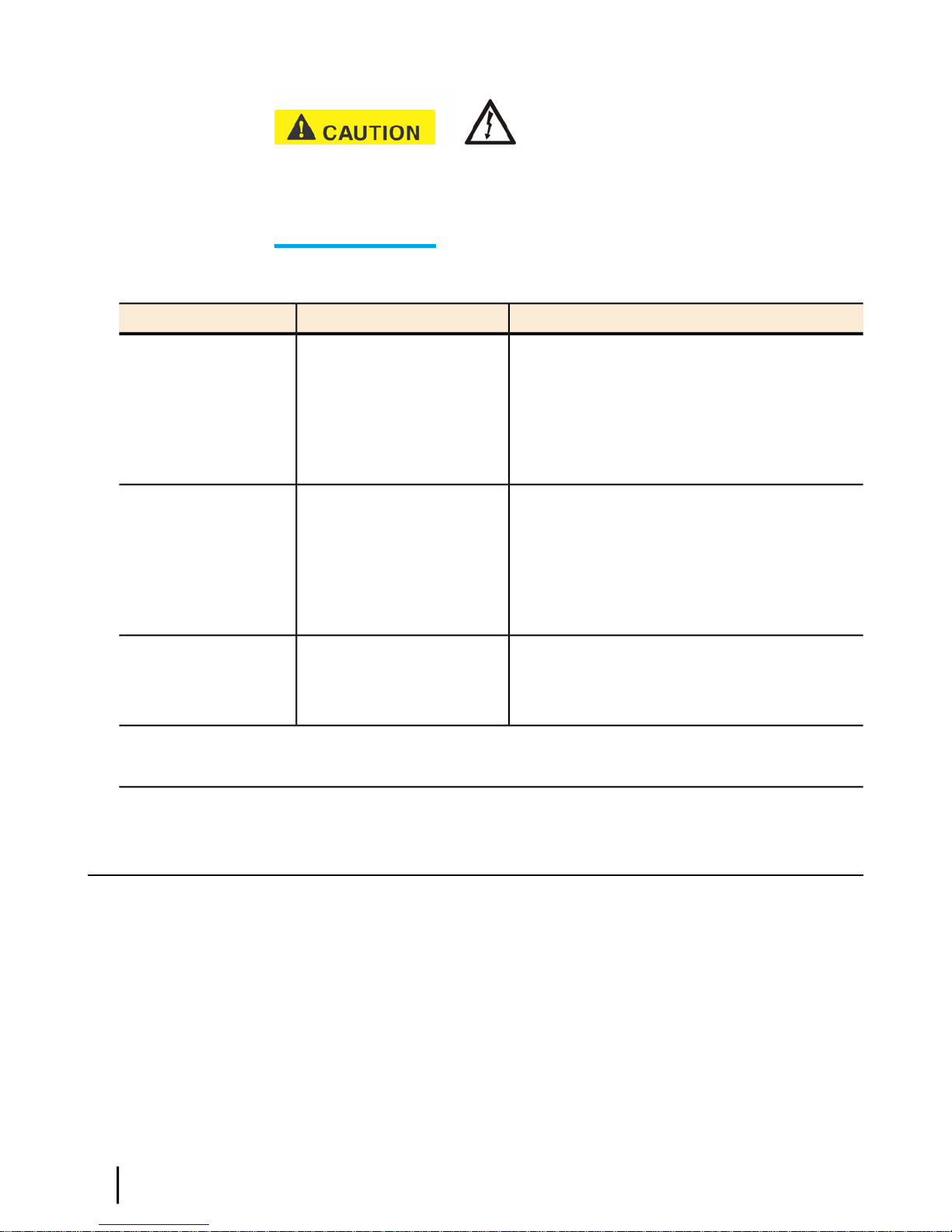
Understanding safety alert messages
Safety alert messages call attention to potential safety hazards and tell you how to avoid them.
These messages are identied by the signal words DANGER, WARNING, CAUTION, or
NOTICE, as illustrated below. To avoid possible property damage, personal injury, or in some
cases possible death, read and comply with all safety alert messages.
Messages concerning personal injury
The signal words DANGER, WARNING, and CAUTION indicate hazards that could result in
personal injury or in some cases death, as explained below. Each of these signal words indicates
the severity of the potential hazard.
DANGER indicates a potentially hazardous situation which, if not
avoided, will result in death or serious injury.
WARNING indicates a potentially hazardous situation which, if
not avoided, could result in death or serious injury.
CAUTION indicates a potentially hazardous situation which, if
not avoided, could result in minor or moderate injury.
Messages concerning property damage
NOTICE is used for messages concerning possible property damage,
product damage or malfunction, data loss, or other unwanted results—but not personal injury.
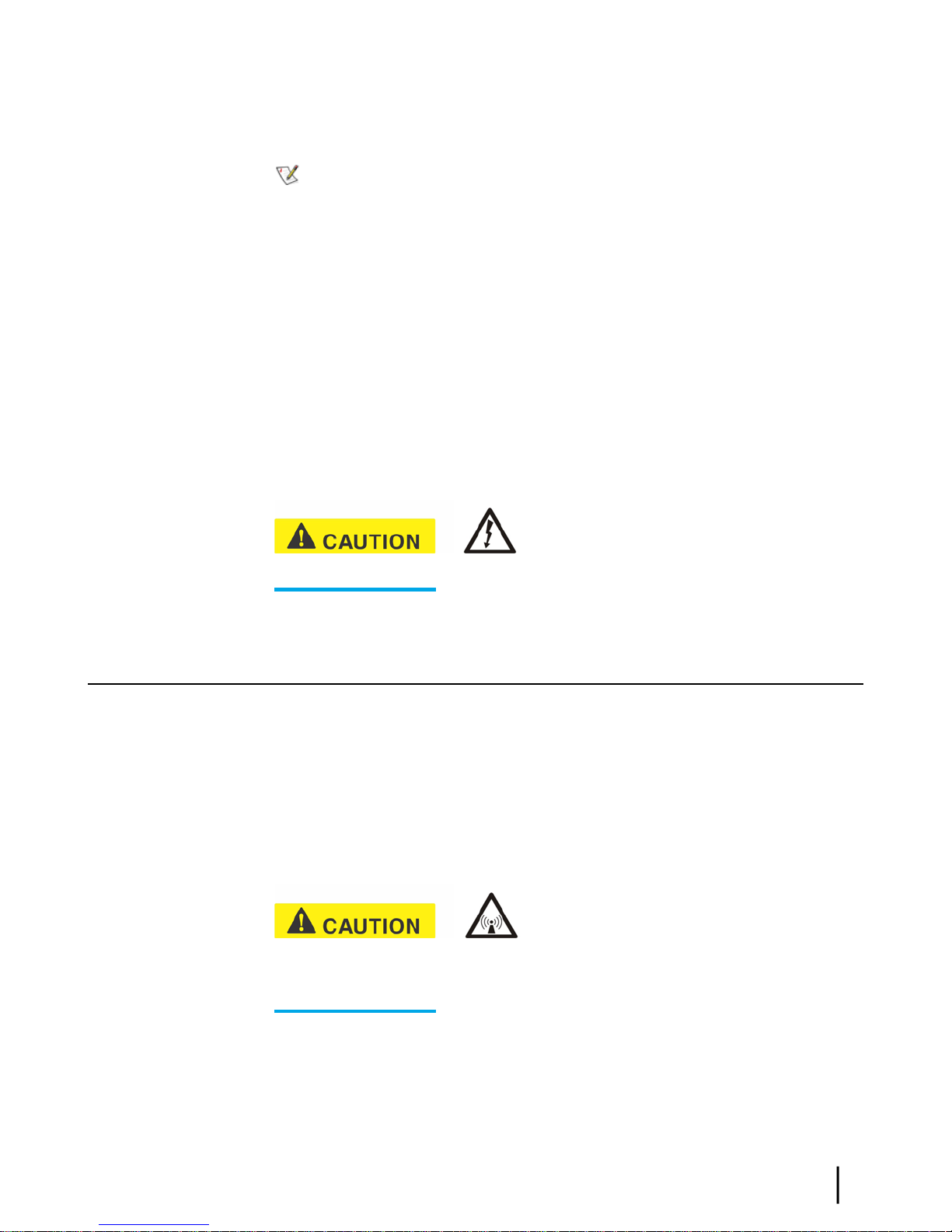
Safety symbols
The generic safety alert symbol calls attention to a potential personal injury hazard.
It appears next to the DANGER, WARNING, and CAUTION signal words as part of the signal
HN9200 Satellite Modem Installation Guide
1038622-0001 Revision B
xi

word label. Other symbols may appear next to DANGER, WARNING, or CAUTION to indicate
a specic type of hazard (for example, re or electric shock). If other hazard symbols are used
in this document they are identied in this section.
Additional symbols
This document also uses these symbols:
Indicates a safety alert message that concerns a potential electric shock hazard.
Indicates a safety alert message that concerns a potentially hazardous situation in
which you could be exposed to radio frequency (RF) energy.
xii
HN9200 Satellite Modem Installation Guide
1038622-0001 Revision B
Chapter
1
Satellite modem overview
Topics:
• Scope of this installation guide
• Satellite modem specifications
The HN9200 satellite modem connects to a satellite network to provide Internet
or intranet service or both to a host—typically a computer—or to multiple hosts
on a wired (Ethernet) or wireless LAN. The modem has an Ethernet port so it
can be connected to a computer or LAN.
The HN9200 can be used in either a Ka-band or Ku-band bent-pipe satellite
network. This installation guide includes instructions for both Ka-band and
Ku-band installations.
Figure 1: HN9200 satellite modem
Terminology
In this installation guide:
•
Satellite modem and modem both refer to the HN9200 satellite modem.
•
Installer Support refers to organizations that provide assistance to
professional installers of Hughes satellite equipment. If you do not know
who provides your support, contact your program manager.
•
Acronyms are identied in Acronyms used in this guide on page 115.
HN9200 Satellite Modem Installation Guide
1038622-0001 Revision B
1

Scope of this installation guide
This installation guide explains how to install, commission, activate, and troubleshoot the HN9200
satellite modem. It also contains certain reference information concerning operation of the
satellite modem, such as troubleshooting information.
Audience
This guide is intended to be used by professional installers. It may also be useful for:
• Trainers who train installers
• Call center operators who respond to customers’ calls
Satellite modem specifications
Table 1: Specifications for the HN9200 satellite modem
Satellite modem overviewChapter 1
Operating temperature range
Protocol support
Network interface ports
Power supplies and power requirements
1.6 lb (0.73 kg)Weight
8.0 inches (20.3 cm)Height
1.6 inches (4.1 cm); 2.4 inches (6.1 cm) at baseWidth
9.0 inches (22.9 cm)Depth
41 ºF to 104 ºF (5 ºC to 40 ºC)
Above 5,000 ft (1,524 m) altitude, the maximum
temperature is reduced by 1 ºC per 1,000 ft (305 m).
5% to 90% non-condensingOperating humidity range
Up to 15,000 ft (4,572 m)Altitude
ConvectionCooling method
TCP/IP (Transmission Control Protocol / Internet
Protocol) protocol suite
Ka-band or Ku-bandSupported frequency ranges
RJ-45 Ethernet LAN port supporting 10BaseT or
100BaseT operation
See Power supply information on page 7.
HN9200 Satellite Modem Installation Guide
2
1038622-0001 Revision B

Chapter
2
Preparing for installation
Topics:
• Installation summary
• Installation checklist
• Items required for installation
• Conducting a site survey
• Power supply information
• Computer and networking
requirements
• Related components
This section describes preparations for installing the satellite modem and includes
information you should know before you begin. Review this information before
you install the satellite modem, antenna assembly, antenna mount, or IFL cables.
Refer also to Installation summary on page 4.
To install the satellite modem, you need the Installation Reference Sheet, which
contains installation parameters and other installation information specic to
your installation site. Print the Installation Reference Sheet for your installation
site from your installation support web site.
HN9200 Satellite Modem Installation Guide
1038622-0001 Revision B
3
Installation summary
This guide explains how to install the HN9200 satellite modem. It includes limited information
about other satellite terminal components. The satellite modem is the small indoor unit. The
satellite terminal includes the satellite modem and the antenna, radio assembly, and IFL cables,
as shown in Figure 2: Satellite modem and related terminal components on page 4.
Preparing for installationChapter 2
Figure 2: Satellite modem and related terminal components
This summary focuses on installation of the satellite modem, but also includes some information
on related tasks such as antenna installation and pointing. The tasks listed below are the main
installation tasks, but these are not all of the installation tasks.
Complete all steps in the order they are presented in this installation guide unless you have a
specic reason for doing them in a different order. In any case, make sure all steps are completed.
You must install the antenna before the satellite modem can be commissioned. Then you point
the antenna as part of the modem commissioning procedure.
Details for the satellite modem installation tasks are included in later chapters in this guide.
Preparing for the installation
• Make sure you have all items required for installation, including the Installation Reference
Sheet, all equipment to be installed, and required tools for the outdoor equipment.
•
Make sure the customer's computer meets the requirements listed in Computer and networking
requirements on page 8.
• Conduct a site survey.
• Assemble and install the antenna and radio as instructed in the antenna installation guide.
Installing the satellite modem
• Connect the transmit and receive cables.
• Connect the modem to the installer laptop.
• Connect the power supply.
• Power up the modem and observe the LEDs to verify normal operation.
Commissioning the modem and pointing the antenna
•
Upload the sbc.cfg le (if you are instructed to upload it).
HN9200 Satellite Modem Installation Guide
4
1038622-0001 Revision B

• Enter the antenna location and satellite and radio parameters.
• Point the antenna.
• Register the satellite modem.
Completing the installation
• Conrm that all les are current.
• Connect the modem to the customer’s computer.
Installation checklist
To help ensure a successful installation, pay careful attention to the items listed in the checklist
below as you install the satellite modem, antenna, and IFL cables.
IFL cables
For specic cable information see Table 3: Related installation documents on page 11.
number.
Chapter 2Preparing for installation
Use only Hughes-approved cables.
Do not exceed maximum length for the ODU type (1 W or 2 W), cable type, and cable part
Do not exceed the cable bend radius.
Properly terminate cables.
Connectors and connections
Use only connector types approved for cable type used. Check all connections for tightness.
Outdoors:
Make sure F connectors connected to the radio assembly are tightened to 20 inch-lb torque.
Carefully follow waterproong procedures, using dielectric grease and Hughes-approved
weatherproof tape.
Power source
Check AC power outlet for correct wiring
Before connecting the modem power supply to the AC power source (using a surge protector),
use an AC outlet tester to verify that the outlet is wired correctly. Wiring problems may include:
• Hot and neutral wires reversed
• Neutral and ground wires reversed
• Open ground (incomplete connection)
• Open neutral
If the outlet is wired improperly, notify the customer you are not permitted to connect the system
to a faulty outlet. Do not proceed with installation until a properly wired outlet is provided.
Check neutral-ground (N-G) voltage
With a digital multimeter set to AC voltage, measure the voltage between neutral and ground
at the AC power outlet. If the N-G voltage measures 2 VAC or greater, please advise the customer
HN9200 Satellite Modem Installation Guide
1038622-0001 Revision B
5

to have an electrician evaluate the electrical power outlet. N-G voltages may have a negative
impact on the performance of electronic equipment.
Grounding (modem, antenna, radio, and IFL)
Adhere to Hughes grounding requirements.
Use only approved ground wires, ground blocks, lugs, and clamps.
For detailed information refer to the appropriate FSB, as listed in Table 3: Related installation
documents on page 11.
Items required for installation
To install the HN9200 satellite modem, you need:
• HN9200 satellite modem
• Power supply (provided in the shipping carton)
• Surge protector (recommended), provided by the customer
• Cat-5 Ethernet cable
•
sbc.cfg le (if you are instructed to upload it)
• Installation Reference Sheet (provided to the installer)
• Welcome to HughesNet quick start guide (1038043-0001) (to give to the customer)
Preparing for installationChapter 2
Notes
sbc.cfg le – If needed, you can download the most current sbc.cfg le from your installation
support web site.
SAN and PIN – Identication numbers are required to register the satellite modem. Customers
who purchased their system from a Hughes retail channel in the United States or Canada receive
an order conrmation e-mail containing their site account number (SAN) and personal
identication number (PIN).
DC/DC power supply – If the site has a DC power source, it requires a DC/DC power supply.
See Table 2: Power supply specications for the HN9200 satellite modem on page 8. The
installer must provide the wire required to assemble the DC input power cable.
Additional equipment
• Antenna
• Hughes antenna pointing tool (DAPT for Ka-band, DAPT or OPI for Ku-band)
• IFL cables, cable connectors, and ground blocks
For more information on these items, see Related components on page 9.
No tools are required to install the modem. For tools needed to install the antenna mount and
antenna and point the antenna, see:
• Antenna Site Preparation and Mount Installation Guide (1035678-0001)
• The installation guide for the antenna model you are installing
HN9200 Satellite Modem Installation Guide
6
1038622-0001 Revision B
Conducting a site survey
Survey the customer site to conrm that the location meets the requirements for installation of
the satellite modem. For complete site survey information, including site requirements, see the
Antenna Site Preparation and Mount Installation Guide (1035678-0001).
The key site survey tasks related to installation of the satellite modem are:
1.
Make sure there is an unobstructed line of sight to the satellite specied on the Installation
Reference Sheet.
2.
Review the Installation Reference Sheet for site-specic instructions.
Power supply information
See also Connecting the power supply on page 17.
The power supply is included in the satellite modem shipping carton.
Chapter 2Preparing for installation
Figure 3: AC power supply for the HN9200 satellite modem
Before proceeding, make sure you have the correct power supply. Check the part number on the
power supply and refer to Figure 3: AC power supply for the HN9200 satellite modem on page
7.
• Always use the power supply provided with the satellite modem. The modem’s performance
may suffer if the wrong power supply is used.
• Connect the AC/DC power supply to a three-wire, grounded outlet with an input of 110/240
VAC. A suitable surge protector is recommended to protect the satellite modem from possible
damage due to power surges.
• Always connect the DC power cord to the HN9200 rear panel before applying power to the
power supply. If you apply power to the power supply and then connect the DC power cord,
the satellite modem may not perform properly and could be damaged.
• Observe the power standards and requirements of the country where it is installed.
HN9200 Satellite Modem Installation Guide
1038622-0001 Revision B
7
Preparing for installationChapter 2
If there isany reason to remove power from the satellite
modem, always unplug the AC power cord from the power source (power outlet, power strip,
or surge protector). Do not remove the DC power cord from the modem’s rear panel. Doing so
could result in an electrical shock or damage the modem.
When you re-apply power to the modem, plug the AC power cord into the power source.
Table 2: Power supply specifications for the HN9200 satellite modem
Electrical requirementsPart numberPower supply type
Input line voltage:1500089-0001AC/DC (64 W)
90 to 264 VAC, 2 A maximum
Input line frequency:
50 to 60 Hz AC
Rated power consumption: 64 W
Input line voltage:1500185-0001AC/DC (80 W)
90 to 264 VAC, 2 A maximum
Input line frequency:
50 to 60 Hz AC
Rated power consumption: 80 W
1033554-0001DC/DC (65 W)
All listed power supplies may be used with a 1 W or 2 W Ka-band or Ku-band radio. All have a detachable
power cord.
Input line voltage:
12 to 24 VDC, 10 A maximum
Rated power consumption: 65 W
Computer and networking requirements
This section lists the requirements for the computer or other device, network, and browser to be
used with the satellite modem.
Computer requirements
The HN9200 satellite modem can be used with any device that supports IP and has a 10/100
BaseT Ethernet LAN port. Typically, the modem is connected to a customer's computer. However,
the HN9200 is self-hosted; it does not require a computer for any of its functions.
Requirements for the computer to be used with the satellite modem are the same for the laptop
computer you use to install the modem and the customer’s computer that will be connected to
the modem. In either case, the computer should meet the minimum requirements specied by
HN9200 Satellite Modem Installation Guide
8
1038622-0001 Revision B
the computer operating system manufacturer and the following networking and browser
requirements.
Make sure the installer laptop is congured to support DHCP.
Note: The satellite modem can be used with a Mac computer that meets these requirements,
but Mac computers are not supported as a tool for installing the satellite modem.
Networking and Internet browser requirements
• Ethernet port
• Ethernet NIC installed on at least one computer, 10/100 BaseT
• Ethernet cable (provided)
• A web browser such as Internet Explorer with proxy settings disabled
Connecting a network – If the customer wants to connect a network to the satellite modem,
this requires an Ethernet hub or other such device. The customer must supply and congure the
hub and cables. Required IP address information is obtained during commissioning.
Static IP address – The computer can be congured to use a static IP address if the HughesNet
service plan provides for one or more static IP addresses. If the computer is congured to use a
specic static IP address, disable DHCP.
Chapter 2Preparing for installation
or connect the power supply to a power source until you are instructed to do so.
Related components
The satellite modem is the indoor component of the satellite terminal. The terminal also includes
the (outdoor) antenna and IFL cables. This section presents information on the outdoor
components and other related equipment. For additional information, see the applicable documents
listed in Table 3: Related installation documents on page 11.
Antenna
You must assemble and install the antenna before you install the satellite modem. You point the
antenna as part of the modem commissioning process.
outdoor antenna assembly. In the United States, the Federal Communications Commission (FCC)
requires professional installation and service of the antenna assembly because it transmits radio
frequency (RF) energy.
Do not connect the powersupply tothe satellite modem,
Only a trained professional installer should install the
The HN9200 satellite modem can be used with a 0.74 m, 0 .98 m, 1.2 m, or 1.8 m two-way
satellite antenna. The antenna assembly is shipped in a separate box.
The main source of information on the antenna is the antenna installation guide. Each antenna
model has its own installation guide. If you do not have the antenna installation guide, nd the
HN9200 Satellite Modem Installation Guide
1038622-0001 Revision B
9
required antenna model on the Installation Reference Sheet; then locate the installation guide
for that model on your installation support web site.
When you install the antenna assembly, read and follow all safety
alerts and instructions in the antenna installation guide and in the Antenna Site Preparation and
Mount Installation Guide (1035678-0001).
IFL cables
Before you can install the satellite modem, you must route the coaxial IFL cables between the
indoor satellite modem location and the antenna. Then you connect the modem and the antenna
by connecting the IFL cable to both components.
The routing path of the IFL cables between the modem and the antenna depends on the building
conguration. Guidelines for installing IFL cables are included in the Antenna Site Preparation
and Mount Installation Guide (1035678-0001).
Requirements for cables, connectors, and ground blocks
You must use approved cable types and connectors to connect the modem to the outdoor satellite
antenna. For grounding, you must use approved ground blocks and grounding connectors. For
detailed specications and information on these components, see the documents listed in Table
3: Related installation documents on page 11.
Preparing for installationChapter 2
The coaxial IFL cables and the ground block to which they are connected must meet the grounding
requirements specied in the following warning:
grounding requirements in Field Service Bulletin (FSB), HNS Broadband Requirements for
RG-6 and RG-11 IFL Cable Connectors, Ground Blocks, and Ground Block Location
(FSB_050518_01). Improper grounding can result in electric shock injury, property damage,
and/or poor modem performance.
Labeling the IFL cables
Label the receive and transmit IFL cables at the outdoor point-of-entry and at the indoor location
where the satellite modem is installed as follows:
•
Wrap a piece of red electrical tape around the receive cable, and mark SAT IN on the tape.
•
Wrap a piece of blue electrical tape around the transmit cable, and mark SAT OUT on the
tape.
Hub or similar network device
If the satellite modem is to be connected to a network, an Ethernet hub, modem, wireless base
station, or other similar device is required. The customer must supply and congure the network
device, including required cables, according to the device manufacturer’s documentation. Required
IP address information is obtained during modem commissioning.
You must comply with applicable local codes and the
10
HN9200 Satellite Modem Installation Guide
1038622-0001 Revision B

Instructions for related components
This installation guide covers only installation of the satellite modem. For installation instructions
for other components, see Table 3: Related installation documents on page 11. You can view
or download these documents at https://dwayinstalls.hns.com/ (click Installer Login Click
Here!!) or your installation support web site. If you cannot log in, contact Installer Support—or
contact your program manager for access to these documents.
Table 3: Related installation documents
Chapter 2Preparing for installation
Where to find instructionsComponent or topic
Safety (all components)
Site survey
Site preparation
Antenna mounts
IFL
IFL cables (specifications, approved
types, maximum lengths)
IFL cable connectors
Grounding
Ground blocks
Antenna, antenna pointing
Radio assembly
Antenna Site Preparation and Mount Installation Guide
(1035678-0001).
For Ku-band installations: Field Service Bulletin (FSB), IFL Cable,
Approved List (with lengths) for DW7x00, DW60xx, and DW40xx
Domestic Installations (FSB__060316_01).
(IFL cable specifications in this FSB apply to HN9200 Ka-band and
Ku-band installations.)
Field Service Bulletin (FSB), HNS Broadband Requirements for
RG-6 and RG-11 IFL Cable Connectors, Ground Blocks, and
Ground Block Location (FSB_050518_01).
See the antenna installation guide for the specific antenna model
you are installing.
For Ka-band antennas, see also the Ka-Band Antenna Pointing
Guide for Bent-Pipe Satellite Networks (1038764-0001).
Antenna pointing for Ku-band antennas is covered in the antenna
installation guide.
HN9200 Satellite Modem Installation Guide
1038622-0001 Revision B
11


Chapter
3
Installing the satellite modem
Topics:
• Prerequisites for installing the
modem
• Selecting the modem installation
location
• Modem operating position
• Connecting the transmit and
receive cables
• Connecting the installer laptop to
the modem
• Connecting the power supply
• Powering up the modem
• LEDS on power-up
Installation of the HN9200 satellite modem consists of physical installation,
followed by commissioning and registration. These processes prepare the modem
for operation on the satellite network. Installation tasks include:
• Physical installation and power-up
• Entering parameters required for commissioning
• Commissioning, including antenna pointing
The installation software is factory pre-installed in the satellite modem. If
necessary, this software is automatically updated as part of the installation
process. You access the installation software through a browser on your installer
computer to perform tasks such as entering required parameters.
HN9200 Satellite Modem Installation Guide
1038622-0001 Revision B
13
Prerequisites for installing the modem
The following are required before you can install, commission, and register the satellite modem:
• The antenna and radio assembly must be installed, as instructed in the antenna installation
guide. (However, you point the antenna as part of the modem commissioning process, which
is explained later in this installation guide.)
• The IFL cables must be installed and connected to the satellite modem and to the radio
assembly (LNB and transmitter).
See also Items required for installation on page 6 and Related components on page 9.
Selecting the modem installation location
Select a location for the satellite modem that will accommodate all required cable connections,
including connection to the power source.
Installing the satellite modemChapter 3
Ventilation and heat sources
Make sure the installation location meets the following requirements concerning ventilation and
heat sources.
• Do not block any of the modem’s ventilation openings.
• Leave 6 inches of space around the top and sides of the modem to ensure adequate ventilation
and prevent overheating.
• Do not place the modem near a heat source such as direct sunlight, a radiator, heat register
or vent, oven, stove, amplier, or other apparatus that produces heat.
Modem operating position
position as shown in Figure 4: HN9200 in vertical position on page 15. Any other position
could result in insufcient ventilation, overheating, and malfunction.
Install and operate the HN9200 modem only in the upright vertical
14
HN9200 Satellite Modem Installation Guide
1038622-0001 Revision B
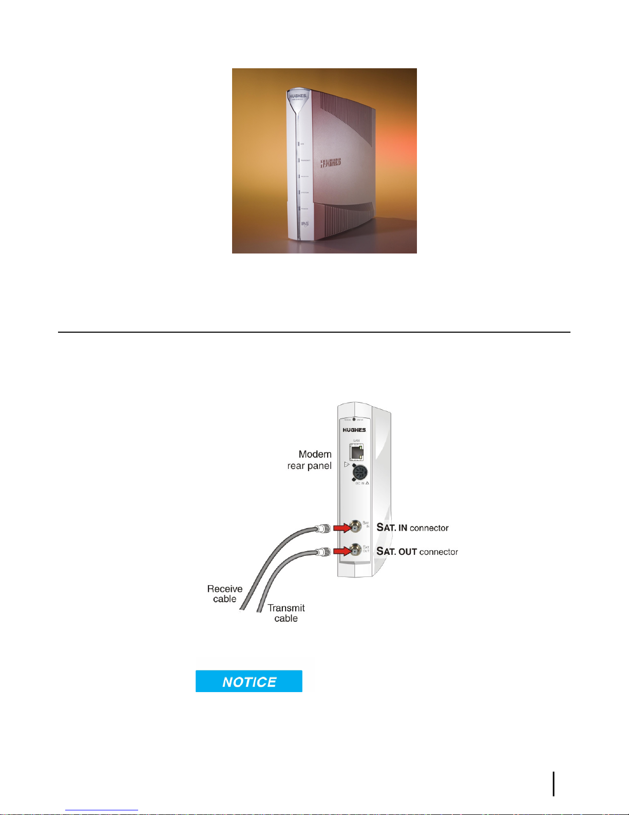
Figure 4: HN9200 in vertical position
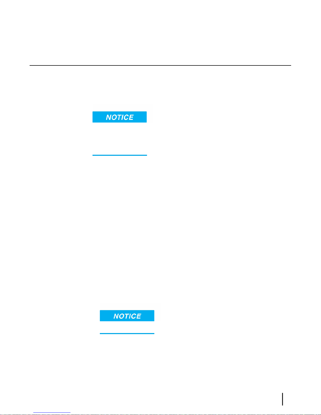
Connecting the transmit and receive cables
Chapter 3Installing the satellite modem
Connect the transmit and receive IFL cables to the satellite modem.
1.
Connect the transmit and receive cables to the connectors on the rear panel of the modem as
shown in Figure 5: Connecting the transmit and receive cables to the modem on page 15.
Figure 5: Connecting the transmit and receive cables to the modem
tightened.
• Make sure each connector is properly aligned (not cross-threaded).
• The connector should be nger tight with no play.
The transmit and receive cable connectors must be securely
HN9200 Satellite Modem Installation Guide
1038622-0001 Revision B
15

Note: The satellite modem may operate correctly when rst installed even if the transmit
and receive cable connectors are not adequately tightened. However, problems could
develop later. Therefore, successful modem operation is not an indication that the cables
are adequately tightened.
2.
Make sure neither the satellite modem nor the customer’s computer are connected to an
Ethernet router or switch.
Note: Do not connect any device to the satellite modem at this time except the installer
laptop computer. Ethernet devices may only be connected to the modem after it is
installed and commissioned.
Connecting the installer laptop to the modem
For this task you need an Ethernet cable.
To access the satellite modem so you can perform the required installation procedures, you
connect your installer laptop computer to the modem. After the modem is installed and registered
with the satellite network, you connect the modem to the customer’s computer or other device.
During modem installation the installer laptop computer must be directly connected to the modem
without any intervening connection.
Installing the satellite modemChapter 3
Connect the installer laptop to the modem:
1.
Use an Ethernet cable to connect your laptop computer directly to the modem’s LAN port,
as shown in Figure 6: Connecting the installer laptop computer to the modem on page 16.
Do not connect the installer laptop to the modem through an Ethernet router or switch.
Figure 6: Connecting the installer laptop computer to the modem
2.
Make sure that neither the satellite modem nor the customer’s computer are connected to an
Ethernet router or switch.
3.
If you are running rewall software on the laptop computer, disable it until you complete
installation of the modem.
16
HN9200 Satellite Modem Installation Guide
1038622-0001 Revision B
The LAN LED on the front of the modem should now be on.
Connecting the power supply
Follow the instructions in Connecting an AC/DC power supply on page 17 or Connecting and
assembling a DC/DC power supply on page 18.
Connecting an AC/DC power supply
• The input must be 120-240 VAC.
• A suitable surge protector is recommended to protect the modem from possible damage due
to power surges.
The customer provides the surge protector. If a surge protector or power strip is not present, use
a wall outlet or other power source.
Chapter 3Installing the satellite modem
The following apply to the AC/DC power supplies:
In some countries, the modem may use a replacement AC power cord. Different countries have
different standards and requirements that must be observed.
Before connecting the modem power supply to the AC power source (using a surge protector),
use an AC outlet tester to verify that the power outlet is wired correctly. Wiring problems may
include:
• Hot and neutral wires reversed
• Neutral and ground wires reversed
• Open ground (incomplete connection)
• Open neutral
If the outlet is wired improperly, notify the customer that you are not permitted to connect the
system to a faulty outlet. Do not proceed with the installation until a properly wired outlet is
provided.
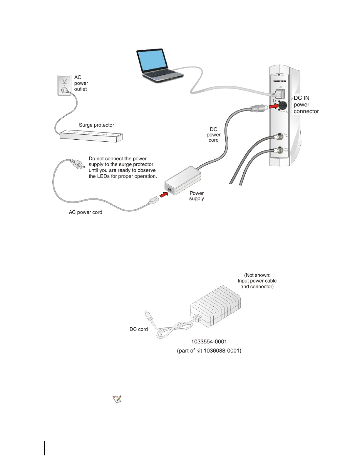
Connect the power supply as follows:
1.
Check Power supply information on page 7 to make sure you have the correct power supply.
2.
Connect the DC power cord to the DC IN port on the modem, as shown in Figure 7:
Connecting an AC power supply on page 18.
If you apply power to the power supply and then connect the
DC power cord, the satellite modem may not perform properly and could be damaged.
3.
Connect the AC power cord to the power supply.
Do not connect the AC power cord to the surge protector at this time. Wait until you are ready
to observe the modem’s LEDs upon power-up, as explained in Powering up the modem on page
19 and LEDS on power-up on page 19.
HN9200 Satellite Modem Installation Guide
1038622-0001 Revision B
17
Installing the satellite modemChapter 3
Figure 7: Connecting an AC power supply
Connecting and assembling a DC/DC power supply
Figure 8: DC/DC power supply on page 18 shows the DC/DC power supply used with the
HN9200 modem.
Figure 8: DC/DC power supply
Connect and assemble the DC/DC power supply as follows:
1.
Connect the DC power cord to the DC IN port on the modem.
2.
Assemble the input power cable according to the wiring diagram included in the cable kit.
18
HN9200 Satellite Modem Installation Guide
1038622-0001 Revision B
Note: The input cable kit is included in the power supply kit. The cable kit contains
an input power connector, connector pins, and a wiring diagram; it does not include
wire.
 Loading...