

Hughes HN7000S, HN7700S User Manual

Hughes
Remote Terminal User Guide
Models: HN7000S, HN7700S
1037073-0001
Revision A
July 18, 2006

Copyright © 2006 Hughes Network Systems, LLC
All rights reserved. This publication and its contents are proprietary to Hughes Network Systems,
LLC. No part of this publication may be reproduced in any form or by any means without the written
permission of Hughes Network Systems, LLC, 11717 Exploration Lane, Germantown, Maryland
20876.
Hughes Network Systems, LLC has made every effort to ensure the correctness and completeness
of the material in this document. Hughes Network Systems, LLC shall not be liable for errors
contained herein. The information in this document is subject to change without notice. Hughes
Network Systems, LLC makes no warranty of any kind with regard to this material, including, but not
limited to, the implied warranties of merchantability and fitness for a particular purpose.
Trademarks
Hughes, Hughes Network Systems, and HughesNet are trademarks of Hughes Network Systems,
LLC. All other trademarks are the property of their respective owners.
Important safety information
For your safety and protection, read this entire guide before you
attempt to use the Hughes HN7000S or HN7700S remote
terminal. In particular, read this safety section carefully. Keep this
safety information where you can refer to it if necessary.
Types of warnings used in this manual
This section introduces the various types of warnings used in this
guide to alert you to possible safety hazards.
WARNING
Indicates a potentially hazardous situation, which, if not
avoided, could result in death or serious injury.
CAUTION
Indicates a potentially hazardous situation, which, if not
avoided, may result in minor or moderate injury.
CAUTION
Indicates a situation or practice that might result in property
damage.
Note: A note provides additional information.
• Important safety information
1037073-0001 Revision A
iii

• Important safety information
iv
1037073-0001 Revision A

Contents
Important safety information . . . . . . . . . . . . . . . . . . . . . iii
Types of warnings used in this manual . . . . . . . . . . . . . . . . . . . iii
About this document . . . . . . . . . . . . . . . . . . . . . . . . . . . xiii
Scope and audience . . . . . . . . . . . . . . . . . . . . . . . . . . . . . . . . . xiii
Organization of this guide . . . . . . . . . . . . . . . . . . . . . . . . . . . . xiii
Conventions . . . . . . . . . . . . . . . . . . . . . . . . . . . . . . . . . . . . . . . xiv
Revision record. . . . . . . . . . . . . . . . . . . . . . . . . . . . . . . . . . . . . xiv
Chapter 1
Introduction . . . . . . . . . . . . . . . . . . . . . . . . . . . . . . . . . . . .1
Contact information . . . . . . . . . . . . . . . . . . . . . . . . . . . . . . . . . . .1
For United States users who purchased through a retail
channel . . . . . . . . . . . . . . . . . . . . . . . . . . . . . . . . . . . . . . . . . . .1
For United States users who purchased through a value added
reseller . . . . . . . . . . . . . . . . . . . . . . . . . . . . . . . . . . . . . . . . . . .1
Remote terminal overview . . . . . . . . . . . . . . . . . . . . . . . . . . . . . .1
System requirements . . . . . . . . . . . . . . . . . . . . . . . . . . . . . . . . . .2
How the remote terminal works . . . . . . . . . . . . . . . . . . . . . . . . . .3
Professional installation or service requirement . . . . . . . . . . . . .4
Grounding requirement . . . . . . . . . . . . . . . . . . . . . . . . . . . . . . . .4
Preventive maintenance . . . . . . . . . . . . . . . . . . . . . . . . . . . . . . . .5
Operating considerations . . . . . . . . . . . . . . . . . . . . . . . . . . . . . . .5
Chapter 2
System Control Center . . . . . . . . . . . . . . . . . . . . . . . . . . .7
Accessing the System Control Center . . . . . . . . . . . . . . . . . . . . .8
Creating a shortcut to the System Control Center . . . . . . . . . .9
Home page . . . . . . . . . . . . . . . . . . . . . . . . . . . . . . . . . . . . . . . . .10
System indicators . . . . . . . . . . . . . . . . . . . . . . . . . . . . . . . . . .10
Links . . . . . . . . . . . . . . . . . . . . . . . . . . . . . . . . . . . . . . . . . . . .11
System status . . . . . . . . . . . . . . . . . . . . . . . . . . . . . . . . . . .11
Test utilities . . . . . . . . . . . . . . . . . . . . . . . . . . . . . . . . . . . .12
Help . . . . . . . . . . . . . . . . . . . . . . . . . . . . . . . . . . . . . . . . . .12
myHughesNet . . . . . . . . . . . . . . . . . . . . . . . . . . . . . . . . . . .12
System status page . . . . . . . . . . . . . . . . . . . . . . . . . . . . . . . . . . .13
Reception information page . . . . . . . . . . . . . . . . . . . . . . . . . . . .14
Transmission information page . . . . . . . . . . . . . . . . . . . . . . . . .15
System information page . . . . . . . . . . . . . . . . . . . . . . . . . . . . . .16
• Contents
1037073-0001 Revision A
v

Connectivity test page . . . . . . . . . . . . . . . . . . . . . . . . . . . . . . . .18
Port forwarding configuration page . . . . . . . . . . . . . . . . . . . . . .18
Defining port forwarding rules. . . . . . . . . . . . . . . . . . . . . . . .18
Help page . . . . . . . . . . . . . . . . . . . . . . . . . . . . . . . . . . . . . . . . . .19
Browsing optimization utility. . . . . . . . . . . . . . . . . . . . . . . . .20
.myHughesNet . . . . . . . . . . . . . . . . . . . . . . . . . . . . . . . . . . . . . .20
Chapter 3
Remote terminal LEDs . . . . . . . . . . . . . . . . . . . . . . . . . .21
Overview . . . . . . . . . . . . . . . . . . . . . . . . . . . . . . . . . . . . . . . . . .21
Fatal error indication . . . . . . . . . . . . . . . . . . . . . . . . . . . . . . . . .22
Weather and signal strength . . . . . . . . . . . . . . . . . . . . . . . . . . . .22
LED appearance during normal operation . . . . . . . . . . . . . . . . .22
Front panel LEDs . . . . . . . . . . . . . . . . . . . . . . . . . . . . . . . . . .23
Ethernet port LEDs. . . . . . . . . . . . . . . . . . . . . . . . . . . . . . . . .23
Additional LED appearance information . . . . . . . . . . . . . . . . . .24
Chapter 4
Troubleshooting . . . . . . . . . . . . . . . . . . . . . . . . . . . . . . . .25
Cannot surf but can access the System Control Center . . . . . . .25
Confirming the terminal is commissioned . . . . . . . . . . . . . . .26
Confirming receive signal . . . . . . . . . . . . . . . . . . . . . . . . . . .27
Confirming transmit signal. . . . . . . . . . . . . . . . . . . . . . . . . . .28
Confirming TCP acceleration is operational . . . . . . . . . . . . .29
Confirming Web Acceleration is operational. . . . . . . . . . . . .30
Confirming NOC connectivity . . . . . . . . . . . . . . . . . . . . . . . .31
Confirming Internet connectivity . . . . . . . . . . . . . . . . . . . . . .33
Checking DNS settings. . . . . . . . . . . . . . . . . . . . . . . . . . . .34
Checking for viruses and firewall issues . . . . . . . . . . . . . . . .34
Cannot access the System Control Center . . . . . . . . . . . . . . . . . 35
Computer is connected directly to the terminal . . . . . . . . . . .35
Terminal is connected to an Ethernet device . . . . . . . . . . . . .35
Using the terminal LEDs to troubleshoot. . . . . . . . . . . . . . . . . .36
Fatal error indication . . . . . . . . . . . . . . . . . . . . . . . . . . . . . . .36
Unrecoverable key error . . . . . . . . . . . . . . . . . . . . . . . . . . . . .36
All LEDs are off . . . . . . . . . . . . . . . . . . . . . . . . . . . . . . . . . . .37
Checking the Power LED. . . . . . . . . . . . . . . . . . . . . . . . . . . .37
Checking the LAN LED. . . . . . . . . . . . . . . . . . . . . . . . . . . . .37
LAN LED is illuminated . . . . . . . . . . . . . . . . . . . . . . . . . . . .38
If the LAN LED stays illuminated . . . . . . . . . . . . . . . . . . .38
If the LAN LED dims. . . . . . . . . . . . . . . . . . . . . . . . . . . . .39
Other devices connected to the terminal . . . . . . . . . . . . . . . . . .40
Receive LED is not illuminated . . . . . . . . . . . . . . . . . . . . . . .40
System LED is not illuminated. . . . . . . . . . . . . . . . . . . . . . . .40
• Contents
vi
1037073-0001 Revision A

Power LED is not illuminated . . . . . . . . . . . . . . . . . . . . . . . .40
Power LED is blinking . . . . . . . . . . . . . . . . . . . . . . . . . . . . . .41
Pedestal base. . . . . . . . . . . . . . . . . . . . . . . . . . . . . . . . . . . . . . . .42
Appendix A
Frequently asked questions (FAQs) . . . . . . . . . . . . . . . .43
Contact information . . . . . . . . . . . . . . . . . . . . . . . . . . . . . . . . . .43
For United States users who purchased through a retail
channel . . . . . . . . . . . . . . . . . . . . . . . . . . . . . . . . . . . . . . . . . .43
For United States users who purchased through a value added
reseller . . . . . . . . . . . . . . . . . . . . . . . . . . . . . . . . . . . . . . . . . .43
General FAQs. . . . . . . . . . . . . . . . . . . . . . . . . . . . . . . . . . . . . . .44
HughesNet Professional FAQs. . . . . . . . . . . . . . . . . . . . . . . . . .47
Appendix B
Typical operating system settings. . . . . . . . . . . . . . . . . .49
Determining if DHCP is enabled on the remote terminal . . . . .49
Configuring Windows for a static IP address. . . . . . . . . . . . . . .50
Windows 98SE or Me . . . . . . . . . . . . . . . . . . . . . . . . . . . . . .51
Windows 2000 . . . . . . . . . . . . . . . . . . . . . . . . . . . . . . . . . . . .54
Windows XP. . . . . . . . . . . . . . . . . . . . . . . . . . . . . . . . . . . . . .57
Configuring Windows to support a DHCP-enabled terminal . . 60
Windows 98SE and Me . . . . . . . . . . . . . . . . . . . . . . . . . . . . .60
Windows 2000 . . . . . . . . . . . . . . . . . . . . . . . . . . . . . . . . . . . .63
Windows XP. . . . . . . . . . . . . . . . . . . . . . . . . . . . . . . . . . . . . .64
Configuring a MacIntosh for a static IP address . . . . . . . . . . . .67
Configuring a MacIntosh to support a DHCP-enabled terminal 69
Appendix C
Home networking. . . . . . . . . . . . . . . . . . . . . . . . . . . . . . .71
Basic wireless considerations. . . . . . . . . . . . . . . . . . . . . . . . .72
Basic Ethernet considerations. . . . . . . . . . . . . . . . . . . . . . . . .73
Appendix D
Conformance with standards and directives. . . . . . . . .75
Safety – operating conditions for Canada . . . . . . . . . . . . . . . . .76
Repairs in Canada. . . . . . . . . . . . . . . . . . . . . . . . . . . . . . . . . .76
Electromagnetic compatibility (EMI) . . . . . . . . . . . . . . . . . . . .77
FCC Part 15 . . . . . . . . . . . . . . . . . . . . . . . . . . . . . . . . . . . . . .77
Canada Class B warning. . . . . . . . . . . . . . . . . . . . . . . . . . . . .77
R&TTE (EU) . . . . . . . . . . . . . . . . . . . . . . . . . . . . . . . . . . . . .78
Telecommunications standards . . . . . . . . . . . . . . . . . . . . . . . . .78
IPoS . . . . . . . . . . . . . . . . . . . . . . . . . . . . . . . . . . . . . . . . . . . .78
FCC Part 68 . . . . . . . . . . . . . . . . . . . . . . . . . . . . . . . . . . . . . .78
Ringer equivalence number (REN) . . . . . . . . . . . . . . . . . . . .79
• Contents
1037073-0001 Revision A
vii

Repairs in the United States . . . . . . . . . . . . . . . . . . . . . . . . . .80
Canada – equipment attachment limitations. . . . . . . . . . . . . .80
Acronyms and abbreviations . . . . . . . . . . . . . . . . . . . . .81
Index . . . . . . . . . . . . . . . . . . . . . . . . . . . . . . . . . . . . . . . . .83
viii
• Contents
1037073-0001 Revision A

Figures
Chapter 1
1. Remote terminal’s role in the system architecture . . . . . . . . . . . . . . . . . . . . . . . .3
Chapter 2
2. System Control Center home page . . . . . . . . . . . . . . . . . . . . . . . . . . . . . . . . . . . .8
3. Creating a shortcut to the System Control Center . . . . . . . . . . . . . . . . . . . . . . . .9
4. Entering the System Control Center URL in the Create Shortcut window . . . . . 9
5. Entering the name of the shortcut. . . . . . . . . . . . . . . . . . . . . . . . . . . . . . . . . . . .10
6. System indicators . . . . . . . . . . . . . . . . . . . . . . . . . . . . . . . . . . . . . . . . . . . . . . . .10
7. System Status indicator reporting a problem . . . . . . . . . . . . . . . . . . . . . . . . . . .11
8. System Status page . . . . . . . . . . . . . . . . . . . . . . . . . . . . . . . . . . . . . . . . . . . . . . .13
9. Reception Information page . . . . . . . . . . . . . . . . . . . . . . . . . . . . . . . . . . . . . . . .14
10. Transmission Information page . . . . . . . . . . . . . . . . . . . . . . . . . . . . . . . . . . . . .15
11. System Information page . . . . . . . . . . . . . . . . . . . . . . . . . . . . . . . . . . . . . . . . . .16
12. Port Forwarding Configuration page . . . . . . . . . . . . . . . . . . . . . . . . . . . . . . . . .18
13. Entering port forwarding rules . . . . . . . . . . . . . . . . . . . . . . . . . . . . . . . . . . . . . .19
14. Help page . . . . . . . . . . . . . . . . . . . . . . . . . . . . . . . . . . . . . . . . . . . . . . . . . . . . . .19
Chapter 3
15. Remote terminal LEDs . . . . . . . . . . . . . . . . . . . . . . . . . . . . . . . . . . . . . . . . . . . .22
16. Ethernet port LED operation . . . . . . . . . . . . . . . . . . . . . . . . . . . . . . . . . . . . . . .23
Chapter 4
17. System Information page . . . . . . . . . . . . . . . . . . . . . . . . . . . . . . . . . . . . . . . . . .26
18. Confirming receive signal . . . . . . . . . . . . . . . . . . . . . . . . . . . . . . . . . . . . . . . . .27
19. Confirming transmit signal. . . . . . . . . . . . . . . . . . . . . . . . . . . . . . . . . . . . . . . . .28
20. Confirming TCP acceleration is operational . . . . . . . . . . . . . . . . . . . . . . . . . . .29
21. Confirming Web Acceleration is operational. . . . . . . . . . . . . . . . . . . . . . . . . . .30
22. Accessing the Connectivity Test page . . . . . . . . . . . . . . . . . . . . . . . . . . . . . . . .31
23. Successful ping test . . . . . . . . . . . . . . . . . . . . . . . . . . . . . . . . . . . . . . . . . . . . . .32
24. Failed ping test . . . . . . . . . . . . . . . . . . . . . . . . . . . . . . . . . . . . . . . . . . . . . . . . . .32
25. Remote terminal power and cable connections . . . . . . . . . . . . . . . . . . . . . . . . .36
26. Attaching the terminal to the pedestal base . . . . . . . . . . . . . . . . . . . . . . . . . . . .42
Appendix B
27. Network dialog with Configuration tab . . . . . . . . . . . . . . . . . . . . . . . . . . . . . . .51
28. TCP/IP Properties . . . . . . . . . . . . . . . . . . . . . . . . . . . . . . . . . . . . . . . . . . . . . . . .52
• Figures
1037073-0001 Revision A
ix

29. Entering the terminal’s IP address . . . . . . . . . . . . . . . . . . . . . . . . . . . . . . . . . . .53
30. Network and Dialup Connections. . . . . . . . . . . . . . . . . . . . . . . . . . . . . . . . . . . .54
31. Local Area Connections . . . . . . . . . . . . . . . . . . . . . . . . . . . . . . . . . . . . . . . . . . .54
32. Local Area Connection Properties . . . . . . . . . . . . . . . . . . . . . . . . . . . . . . . . . . .55
33. TCP/IP Properties . . . . . . . . . . . . . . . . . . . . . . . . . . . . . . . . . . . . . . . . . . . . . . . .56
34. Network and Dialup Connections. . . . . . . . . . . . . . . . . . . . . . . . . . . . . . . . . . . .57
36. TCP/IP Properties . . . . . . . . . . . . . . . . . . . . . . . . . . . . . . . . . . . . . . . . . . . . . . . .58
35. Local Area Connections . . . . . . . . . . . . . . . . . . . . . . . . . . . . . . . . . . . . . . . . . . .58
37. Entering the preferred DNS server address . . . . . . . . . . . . . . . . . . . . . . . . . . . .59
38. Control Panel . . . . . . . . . . . . . . . . . . . . . . . . . . . . . . . . . . . . . . . . . . . . . . . . . . .60
39. Network window . . . . . . . . . . . . . . . . . . . . . . . . . . . . . . . . . . . . . . . . . . . . . . . .61
40. TCP/IP Properties . . . . . . . . . . . . . . . . . . . . . . . . . . . . . . . . . . . . . . . . . . . . . . . .61
41. Gateway tab . . . . . . . . . . . . . . . . . . . . . . . . . . . . . . . . . . . . . . . . . . . . . . . . . . . .62
42. Network and Dialup Connections. . . . . . . . . . . . . . . . . . . . . . . . . . . . . . . . . . . .63
43. Local Area Connection Properties . . . . . . . . . . . . . . . . . . . . . . . . . . . . . . . . . . .63
44. Internet Protocol Properties . . . . . . . . . . . . . . . . . . . . . . . . . . . . . . . . . . . . . . . .64
45. Network Connections . . . . . . . . . . . . . . . . . . . . . . . . . . . . . . . . . . . . . . . . . . . . .65
46. Local Area Connection Properties . . . . . . . . . . . . . . . . . . . . . . . . . . . . . . . . . . .66
47. Internet Protocol Properties . . . . . . . . . . . . . . . . . . . . . . . . . . . . . . . . . . . . . . . .66
48. Mac Systems Preferences menu . . . . . . . . . . . . . . . . . . . . . . . . . . . . . . . . . . . . .67
49. Mac Network screen. . . . . . . . . . . . . . . . . . . . . . . . . . . . . . . . . . . . . . . . . . . . . .68
50. Select Manually from the Configure drop-down list . . . . . . . . . . . . . . . . . . . . .68
51. Mac System Preferences menu. . . . . . . . . . . . . . . . . . . . . . . . . . . . . . . . . . . . . .69
52. Mac Network screen. . . . . . . . . . . . . . . . . . . . . . . . . . . . . . . . . . . . . . . . . . . . . .70
53. Select DHCP from the Configure drop-down menu . . . . . . . . . . . . . . . . . . . . .70
• Figures
x
1037073-0001 Revision A
Appendix C
54. Site with remote terminal and wireless LAN . . . . . . . . . . . . . . . . . . . . . . . . . . .72
55. Site with remote terminal and wired Ethernet LAN. . . . . . . . . . . . . . . . . . . . . .73
Appendix D
56. IPoS symbol . . . . . . . . . . . . . . . . . . . . . . . . . . . . . . . . . . . . . . . . . . . . . . . . . . . .78

Tables
Chapter 3
1. Remote terminal LED operation. . . . . . . . . . . . . . . . . . . . . . . . . . . . . . . . . . . . .24
Appendix D
2. HN7000S and HN7700S standards compliance. . . . . . . . . . . . . . . . . . . . . . . . .75
• Tables
1037073-0001 Revision A
xi

xii
• Tables
1037073-0001 Revision A

About this document
Scope and audience
Organization of this guide
This guide describes components and features common to both
Hughes HN7000S and HN7700S remote terminals. The
HN7000S is a satellite-based remote terminal designed for
Internet access for consumers and Small Office Home Office
(SOHO) entrepreneurs. The HN7700S is an enterprise-class
broadband communications solution used by enterprise
customers, which are typically large businesses.
The audience for this guide consists of end users of the
equipment, including consumers, small office entrepreneurs,
telecommunications managers, planners, and technicians.
Certain procedures, contact information, parts, and other
operational considerations may vary depending on the user’s
location. This manual identifies those differences when
applicable.
The HN7700S Supplemental User Guide Information
(1037075-0001) discusses components and features unique to the
HN7700S terminal.
This guide is organized into the following chapters and
appendices:
Chapter 1 – Introduction describes the remote terminal and
explains how it functions within the Hughes system architecture.
Chapter 2 – System Control Center describes the terminal’s
internal web interface used to access system information.
Chapter 3 – Remote terminal LEDs explains the LEDs on the
front of the terminal.
Chapter 4 – Troubleshooting provides troubleshooting strategies.
Appendix A – Frequently asked questions (FAQs) lists answers
to frequently asked questions about the terminal and the
HughesNet service.
Appendix B – Typical operating system settings explains how to
configure operating system settings so your computer can
communicate with the terminal.
• About this document
1037073-0001 Revision A
xiii
Appendix C – Home networking describes how the terminal
functions in a home network.
Appendix D – Conformance with standards and directives lists
standards and directives that apply to the HN7000S and
HN7700S.
This guide also contains a list of abbreviations and acronyms and
an index.
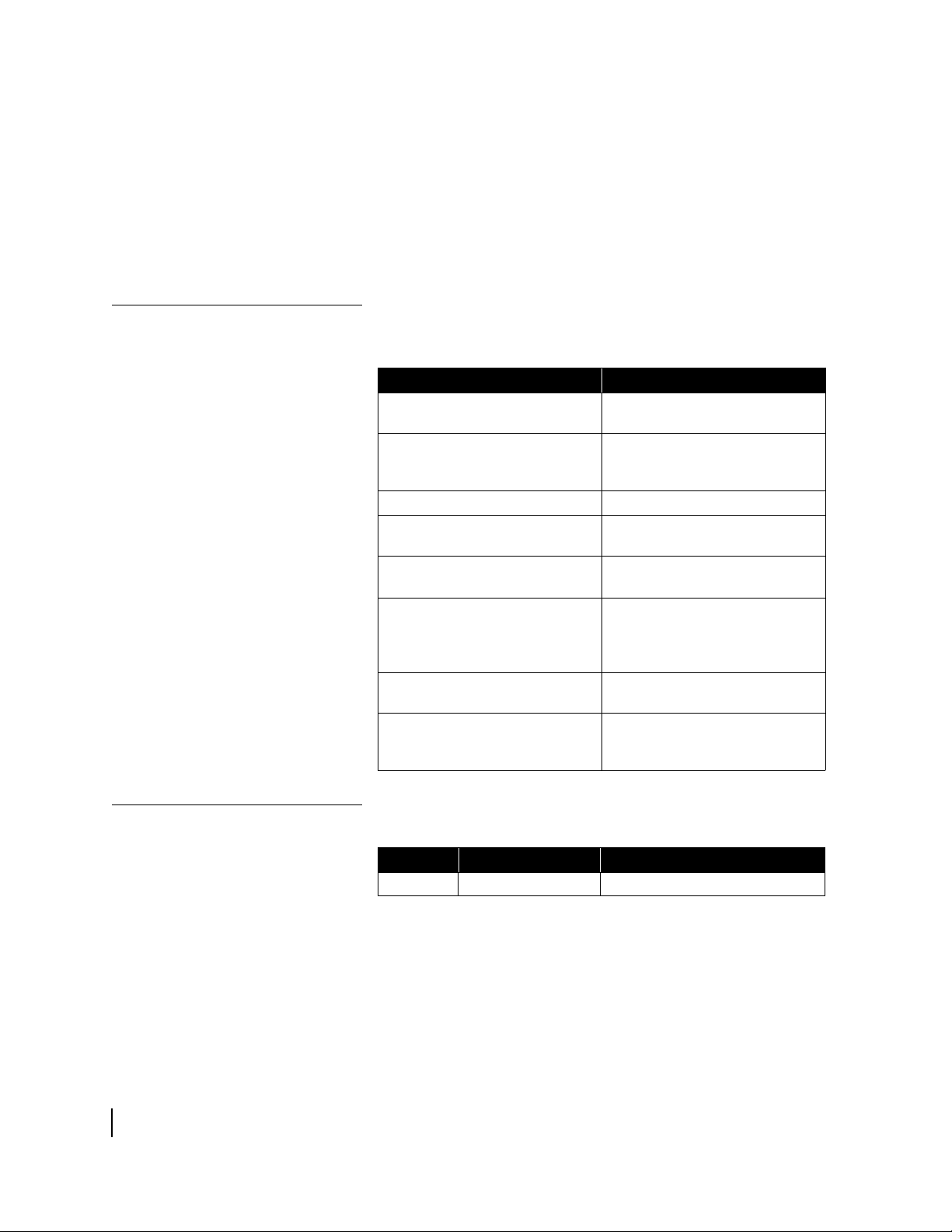
Conventions
This manual follows the typographical conventions shown below
to help clarify instructions:
Example Explanation
Click Exit.
The system displays the following:
Are you ready?
Type exit
Enter a value in the Time field.
Retrieve the following file:
O:\template\techman_r3
Press ALT+V to view the menu.
Select the Edit menu.
Go to Edit → Spelling Checker
Indicates the names of command
buttons that execute an action.
Indicates all system messages
and prompts as the system
displays them.
Indicates operator input.
Indicates the names of fields on
windows.
Indicates file names or file paths
referenced in the manual.
Indicates function or keyboard
keys. Press two keys
simultaneously—in this case, Alt
and V.
Indicates the names of menu bar
options on a software screen.
Indicates a menu/submenu
sequence for selecting an action
or option
Revision record
xiv
• About this document
1037073-0001 Revision A
Revision Date of issue Scope
A 07/18/06 Production release

Chapter 1
Introduction
This chapter discusses general topics related to the remote
terminal. Topics include:
• Contact information on page 1
• Remote terminal overview on page 1
• System requirements on page 2
• How the remote terminal works on page 3
• Professional installation or service requirement on page 4
• Grounding requirement on page 4
• Preventive maintenance on page 5
• Operating considerations on page 5
Contact information
For United States users who
purchased through a retail
channel
For United States users who
purchased through a value
added reseller
Remote terminal overview
If you need warranty or repair support, your contact information
varies depending on your location.
If you purchased this product through a retail channel:
• Access the System Control Center by launching a browser,
typing
location bar, and pressing E
location bar if you are unable to access the System Control
Center with the
• Check our web site www.myHughesNet.com for more
information.
• Send an e-mail to technical support by selecting Email under
Help Center on our
• Call 1-866-347-3292.
If you purchased this product from one of our value added
reseller (VARs), do not contact Hughes. Contact your VAR
according to the procedure supplied by them for technical
support. They are trained to help you with any technical problem.
After your terminal has been professionally installed, you can use
a web browser to surf the Internet. You will also be able to
operate a local area network (LAN) after you configure your
computers with network interface cards (NICs), connect them
www.systemcontrolcenter.com in the URL
NTER. Type 192.168.0.1 in the
www.systemcontrolcenter.com URL.
www.myHughesNet.com web site.
Chapter 1 • Introduction
1037073-0001 Revision A
1

with Ethernet cable or through a wireless base station, and
configure your computers’ operating system network properties.
The terminal has a System Control Center that provides access to
system information such as your site account number (SAN), site
ID, terminal Internet Protocol (IP) address, and subnet mask; the
terminal IP address and the subnet mask may be required to
configure a network. The System Control Center is described in
Chapter 2 – System Control Center, on page 7.
The instructions in this manual also apply to the enterprise-class
HN7700S terminal. The HN7700S terminal includes the
functionality of an HN7000S terminal in addition to being
equipped with an internal telephone modem, serial port, and two
Ethernet ports. The model number appears on a label next to the
DC IN connector on the back of the terminal.
In this guide, the terms remote terminal and terminal may refer to
an HN7000S or HN7700S model remote terminal. The terms
HN7000S and HN7700S are used when it is necessary to
differentiate between the two models.
System requirements
Make sure your computer meets the following minimum
requirements to achieve optimal terminal performance:
• Operating system
– PC: Windows 98 Second Edition (SE), Windows
Millennium Edition (Me), Windows 2000, Windows XP
– MAC: 10.1 or higher
• Processor
– PC: Pentium II 333 Mhz or faster
– MAC: 300 Mhz or faster
• Memory
– PC: 64MB RAM, Windows 98SE and Me; 128MB RAM
Windows 2000 and XP.
– MAC: 128MB
• Free hard drive space
– PC: 100MB
– MAC: 150MB
Chapter 1 • Introduction
2
1037073-0001 Revision A
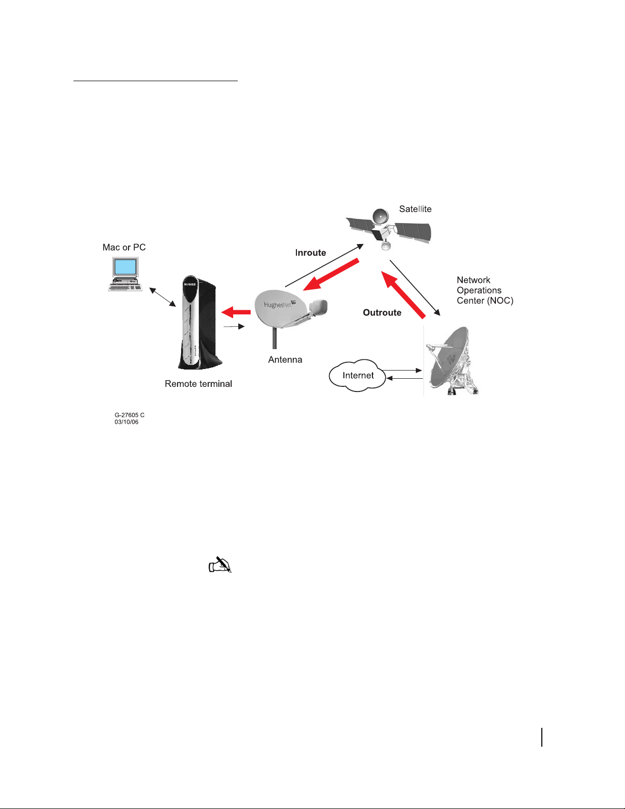
How the remote terminal works
Figure 1 shows how the remote terminal fits into the Hughes
system architecture. The remote terminal is independent of the
operating systems of the computers connected to it, meaning a
computer using a Windows or MacIntosh operating system can
browse the Internet when connected to the terminal. The terminal
is a self-hosted unit, meaning the software required to operate the
terminal resides in the terminal; there is no need to install
software on the computer(s) connected to the terminal.
Figure 1: Remote terminal’s role in the system architecture
The terminal, in combination with an antenna, can also provide
satellite connectivity for multiple computers on a wireless or
wired (Ethernet) LAN. After the terminal and network are
installed, every computer on the network can surf the Internet. To
learn more about using the terminal with a network, see
Appendix C – Home networking.
Note: You can connect multiple home computers and laptops to
a single Internet connection at no additional cost. To do this, you
need to have home networking equipment, which is not included
with this product. For network setup, support and configuration,
contact your network hardware manufacturer and/or operating
system software developer Hughes is not responsible for home
network management and troubleshooting). Simultaneous use of
high bandwidth applications by multiple users may result in
degradation of speed. Actual speeds may vary. Speed and
uninterrupted use of service are not guaranteed.
Chapter 1 • Introduction
1037073-0001 Revision A
3
Professional installation or service requirement
The Federal Communications Commission (FCC) requires
professional installation and service of the two-way antenna
assembly because it transmits radio frequency (RF) energy.
CAUTION
• The two-way satellite dish must be installed in a location
or manner not readily accessible to children and so that
the dish bottom is at least 5 feet above ground level.
• Professional installation or service of the two-way
satellite dish is required by the Federal
Communications Commission because the antenna
transmits radio frequency energy.
• This device emits radio frequency energy when in
transmit mode. To avoid injury, do not place head or
other body parts between the feed horn and satellite
dish when the system is operational.
• Unplug the indoor power connection before performing
maintenance or adding upgrades to any satellite dish
components.
• Do not allow anything to come in contact with the front
surface of the satellite dish.
Grounding requirement
The coaxial cable and the ground block to which it is connected
must meet specific grounding requirements. The requirements are
listed in the following warning.
WARNING
The coaxial cable must be connected to a ground block. The
ground block should be located at the point where the
coaxial cable enters the building. The ground wire must be
connected to the ground block and routed to the earth
ground.
Chapter 1 • Introduction
4
1037073-0001 Revision A
Preventive maintenance
To maintain your terminal:
• Keep the convection cooling vents free from blockage.
• Dust the unit as often as needed with a soft cloth.
• Do not use solvent or abrasive powder when cleaning.
No internal cleaning or service is required. The terminal does not
contain user serviceable parts. Opening or tampering with the
unit voids its warranty.
Operating considerations
You must observe the warnings and cautions below to prevent
personal injury or damage to the terminal.
WARNING
• Do not insert objects through the vents.
• Inserting objects through the vents may result in severe
personal injury or death due to electric shock.
• In addition, inserting objects through the vents may
damage the terminal.
CAUTION
• Keep the terminal in a well-ventilated space. Do not
place anything on top of it. Doing so may reduce heat
dissipation and cause operational problems or damage
the unit.
• Do not install near heat sources, such as radiators, heat
registers, stoves, or other apparatus (including
amplifiers) that produce heat.
• Never unplug the DC power cord from the terminal while
it is powered on. Doing so could damage the pins and
also cause a short in the system.
• When power needs to be removed from a terminal that
uses an AC/DC power supply, always unplug the AC
power cord from the wall outlet, surge protector, or
power strip.
• When power needs to be removed from a terminal that
uses a DC/DC power supply, always unplug the DC input
cable connector from the power supply.
• Do not place the terminal near equipment that produces
dust. Certain copiers or computer printers produce
carbon dust which can cause malfunctions.
• Position the terminal on a stable surface where it will
not be bumped or dropped.
• Prevent moisture from getting inside the terminal.
Chapter 1 • Introduction
1037073-0001 Revision A
5

Chapter 1 • Introduction
6
1037073-0001 Revision A

Chapter 2
System Control Center
The HN7000S has an embedded System Control Center that is a
web interface providing access to important system information,
configuration parameters, documentation, and help topics. Access
the System Control Center by opening a web browser on a
computer connected to the terminal and browsing to
www.systemcontrolcenter.com.
Note: Each terminal’s software is updated periodically over the
satellite link. Always refer to the System Control Center’s Help
page for current information about the System Control Center and
the terminal’s software.
The HN7700S also has a System Control Center, which is
described in the HN7700S Supplemental User Guide
(1037075-0001).
This chapter discusses the following System Control Center
topics:
• Accessing the System Control Center on page 8
• Home page on page 10
• System status page on page 13
• Reception information page on page 14
• Transmission information page on page 15
• System information page on page 16
• Connectivity test page on page 18
• Port forwarding configuration page on page 18
• Help page on page 19
• myHughesNet on page 20
Chapter 2 • System Control Center
1037073-0001 Revision A
7
Accessing the System Control Center
Use any web browser, such as Internet Explorer or Netscape, to
access the System Control Center. During installation, a shortcut
to the System Control Center was placed on your desktop. If there
is not a shortcut on your desktop, follow the instructions below to
access the System Control Center. If you cannot access the
System Control Center after completing the instructions, refer to
Cannot access the System Control Center on page 35.
1. Go to Start→Programs→Internet Explorer (or Netscape). The
browser interface appears.
2. Place the cursor in the Internet Explorer Address bar or the
Netscape Location Bar.
3. Type www.systemcontrolcenter.com.
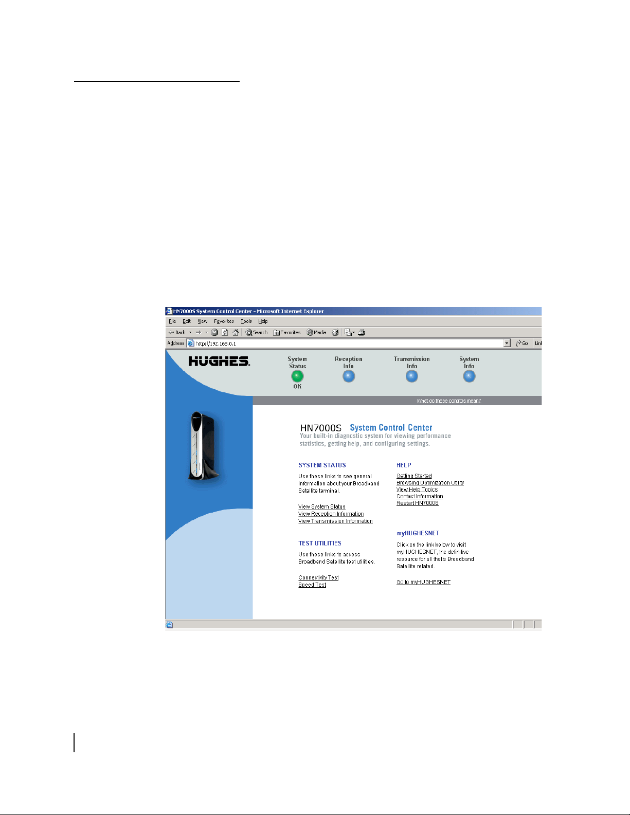
4. Press ENTER. The System Control Center home page shown
in
Figure 2 appears.
Chapter 2 • System Control Center
8
1037073-0001 Revision A
Figure 2: System Control Center home page
If there is not a shortcut on the desktop and
www.systemcontrolcenter.com does not work, type
http://192.168.0.1 in the Internet Explorer Address or
Netscape Location bar and press E
NTER. The System Control
Center should appear. If you cannot access the System Control
Center, see
Cannot access the System Control Center on page 35.
Creating a shortcut to the
System Control Center
Follow these steps to create a shortcut to the System Control
Center if there is not one on your desktop:
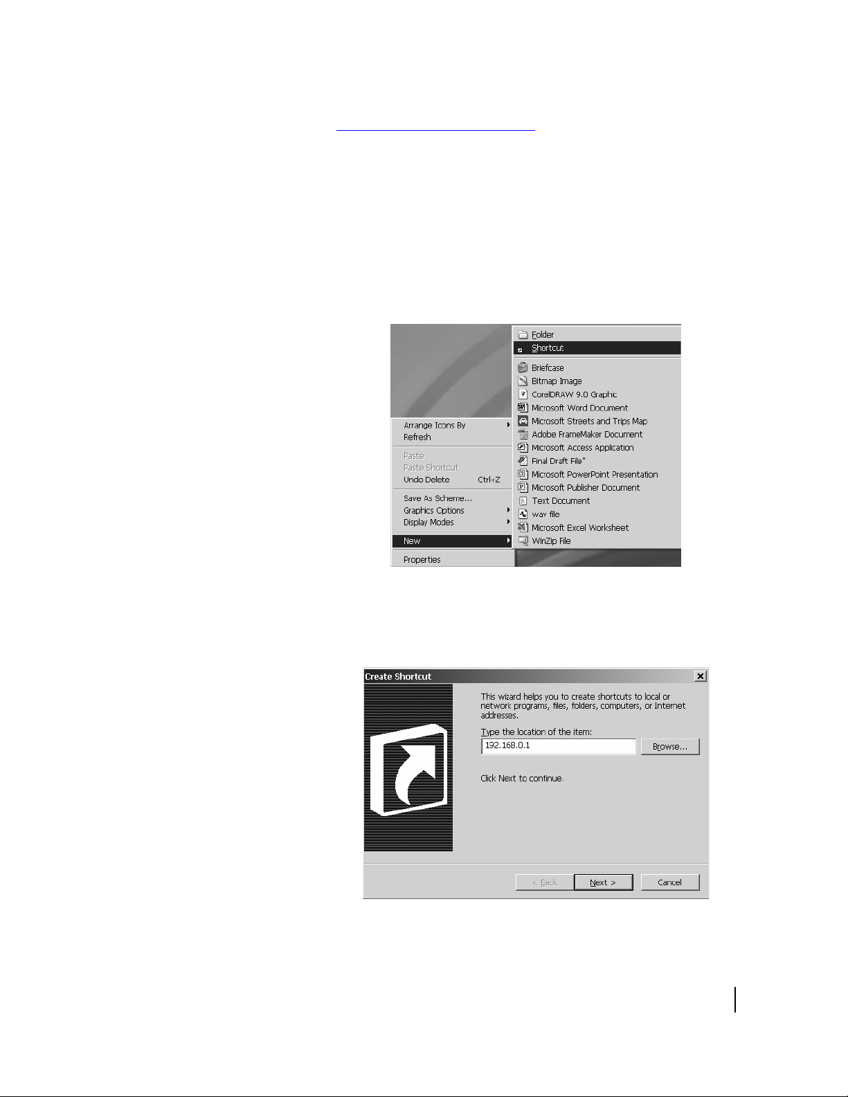
1. Place your cursor on the computer desktop.
2. Right-click and select New→Shortcut as shown in Figure 3.
Figure 3: Creating a shortcut to the System Control Center
3. Type 192.168.0.1 in the field on the Create Shortcut
window as shown in
Figure 4.
Figure 4: Entering the System Control Center URL in the Create
Shortcut window
Chapter 2 • System Control Center
1037073-0001 Revision A
9
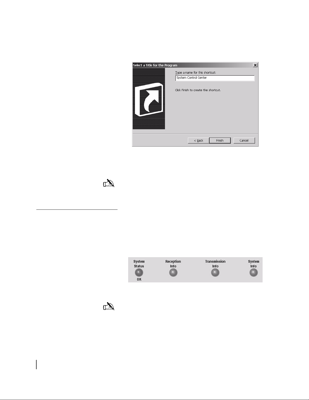
4. Click Next.
5. Type System Control Center in the field on the Select a
Title for the Program window as shown in
Figure 5: Entering the name of the shortcut
Figure 5.
6. Click Finish to save the shortcut to your desktop.
Note: You can also add the System Control Center to your
browser’s Favorites or Bookmark list; refer to your browser’s
documentation for instructions.
Home page
System indicators
The System Control Center home page has system indicators and
links to terminal features and important information regarding the
operation of your terminal.
The system indicators appear at the top of the home page. The
system indicators are described below and are shown in
Figure 6: System indicators
Note: The System Status indicator may be red, yellow, or green
while other indicators are always blue.
Figure 6.
10
Chapter 2 • System Control Center
1037073-0001 Revision A
• System Status provides access to the System Status page.
The System Status page displays general system status
information such as signal strength and commissioning
status.
page 13.
If the indicator is green and OK appears below it, as shown in
Figure 6, the satellite connection is operating properly.
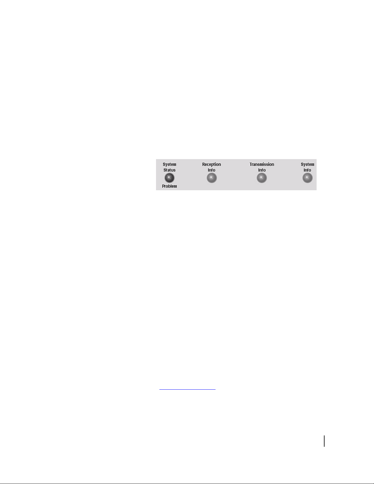
If the indicator is red and Problem appears below it, as
shown in
connectivity. Click the indicator to access the System Status
page to view problem details.
If the indicator is yellow, Web Acceleration is being
bypassed.
• Reception Info provides access to the Reception Information
page, which displays terminal receive data.
information, see Reception information page on page 14.
• Transmission Info provides access to the Transmission
Information page, which displays terminal transmit data.
more information, see Transmission information page on
page 15.
• System Info provides access to the System Information page,
which displays system information such as the terminal IP
address, SAN, and the site ID.
System information page on page 16.
For more information, see System status page on
Figure 7, there is a problem with satellite
Figure 7: System Status indicator reporting a problem
For more
For
For more information, see
Links
System status The following links provide access to system status information:
The System Control Center home page has four groups of links:
• System Status
• Test Utilities
• Help
• myHughesNet (visible only to users in the United States who
purchased a unit through a retail channel)
• View System Status provides access to the System Status
page, which displays general system status information such
as signal strength and commissioning status.
information, see System status page on page 13.
Chapter 2 • System Control Center
1037073-0001 Revision A
For more
11

• View Reception Information provides access to the
Reception Information page, which displays terminal receive
data.
For more information, see Reception information page
on page 14.
• View Transmission Information provides access to the
Transmission Information page, which displays terminal
transmit data.
For more information, see Transmission
information page on page 15.
Test utilities The Connectivity Test link provides access to the Connectivity
Test page, which can be used to test the connection between your
terminal and the Network Operations Center (NOC).
For more
information, see Connectivity test page on page 18.
Help The following links provide access to help-related information:
• Getting Started explains how the terminal works and
provides access to operating instructions and recommended
settings.
• Browsing Optimization Utility provides access to a utility
that enhances web browsing performance. The utility has no
effect on download and upload speeds.
• View Help Topics provides access to the Help page. Refer to
the Help page for a variety of help topics ranging from an
overview of the terminal to answers to frequently asked
questions.
For more information, see Help page on page 19.
• Contact Information provides access to technical support
contact information. The contact information displayed may
vary by service plan.
• Restart HN7000S enables you to restart the terminal.
12
myHughesNet The Go to myHughesNet link provides access to
Chapter 2 • System Control Center
1037073-0001 Revision A
myHughesNet.com, a valuable resource for additional features
and information. Access to
myHughesNet.com is determined by
the service plan you purchased. This feature is not shown in the
sample figures that follow.
Note: myHughesNet will be visible only to users in the United
States who purchased their unit through a retail channel.
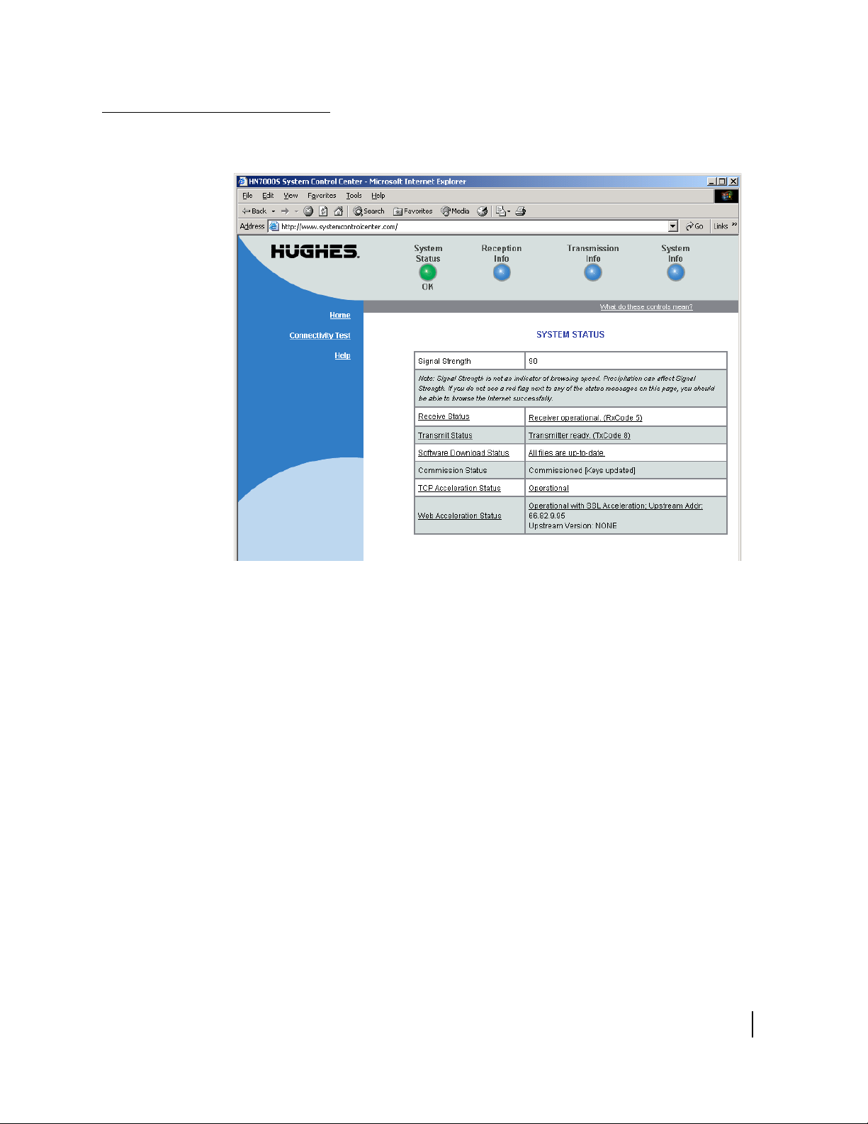
System status page
The System Status page is shown in Figure 8.
Figure 8: System Status page
• Signal Strength - displays the receive signal strength. A value
of 30 or less indicates an appropriate signal is not being
received. Refer to
more information on factors that might affect signal strength.
• Transmit Status - indicates whether the transmit data path is
operational. Clicking on the status message displays
corresponding help information.
• Receive Status - indicates if the receive data path is
operational. Clicking on the status message displays
corresponding help information.
• Software Download Status - indicates whether HN7000S
software and configuration is current.
• Commission Status - indicates whether or not the HN7000S
is commissioned.
• TCP Acceleration Status - indicates whether or not TCP
Acceleration is operational. TCP acceleration must be
operational for optimal performance on an HN7000S.
Weather and signal strength on page 22 for
Chapter 2 • System Control Center
1037073-0001 Revision A
13

• Web Acceleration Status - indicates whether or not Web
Acceleration is operational. If it is operational the server ID
will also be displayed. Web Acceleration is operational if you
have recently browsed HTTP-based web sites. Web
Acceleration may be inactive if you are browsing on a secure
HTTP site (https). Secure HTTP does not support Web
Acceleration, which will resume operation once you return to
an HTTP site. The status indicator will be yellow if Web
Acceleration is being bypassed.
Reception information page
The Reception Information page is shown in Figure 9.
Figure 9: Reception Information page
• Receive Status - reports the status of the receive data path.
Clicking on the blue status message displays corresponding
help information.
• Frames Received - reports the number of data messages
received by the HN7000S over the satellite link.
• Frames with Errors - reports the percentage of frames
received that were corrupted. A continuously increasing
value indicates problems in the receive path. This may
happen in adverse weather conditions or if there is a problem
with the receive cable or the antenna. However, if a low
non-increasing value is displayed and the system is
functioning, there is no reason for concern. You do not need
to do any troubleshooting or contact customer support.
14
Chapter 2 • System Control Center
1037073-0001 Revision A
• Bad Key Frames - indicates the percentage of received
frames that could not be decrypted successfully. All data
received over the satellite is encrypted. A continuously
increasing value indicates the HN7000S is not
commissioned. Click on System Status and check the
Commission Status field on the page that appears. If it
indicates the HN7000S is not commissioned, contact
customer support.
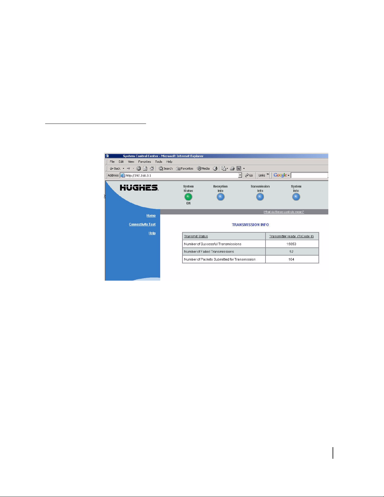
Transmission information page
The Transmission Information page is shown in Figure 10.
Figure 10: Transmission Information page
• Transmit Status - reports the status of the transmit data path.
Clicking on the blue status message displays corresponding
help information.
• Number of Successful Transmissions - reports the number of
successful transmissions (frames) to the satellite.
• Number of Failed Transmissions - reports the number of
frames that could not be sent. A continuously increasing
value indicates a problem with transmitting. However, if a
low non-increasing value is displayed and the system is
functioning, there is no reason for concern. You do not need
to troubleshoot or contact customer support.
• Number of Packets submitted for transmission - indicates the
total number of data packets transmitted.
Chapter 2 • System Control Center
1037073-0001 Revision A
15
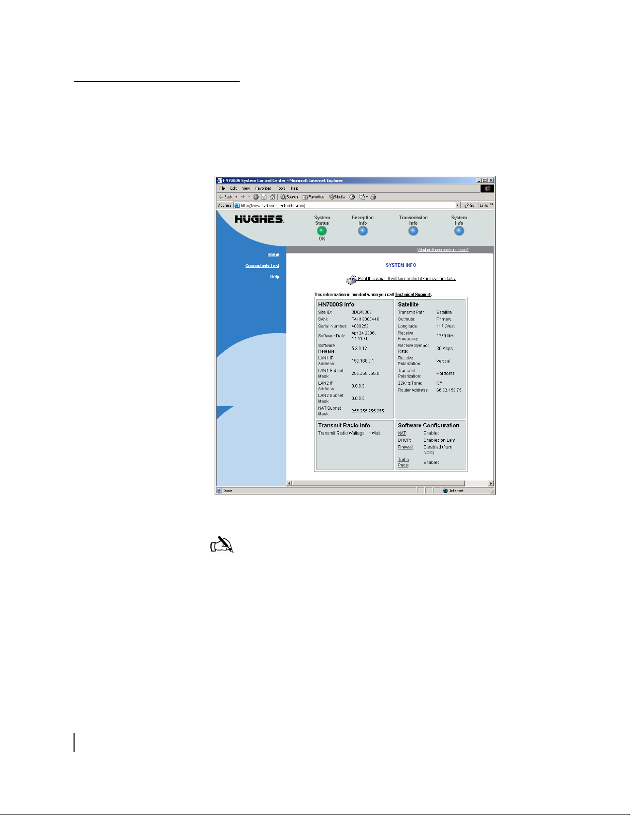
System information page
The System Information page shown in Figure 11 has four
sections: HN7000S Info, Satellite, Software Configuration, and
Transmit Radio Info. Each section displays a number of fields.
While all of the information displayed in the fields may be useful
at some time, the most important fields are discussed below.
16
Chapter 2 • System Control Center
1037073-0001 Revision A
Figure 11: System Information page
Note: Print the System Information page and save it. The System
Information page may not be accessible if a problem occurs; the
printed copy of the System Information page is useful if you need
to contact your service provider for assistance.
• HN7000S Info
– Site ID - site identification number.
– SAN - site account number.
– Serial Number - HN7000S serial number. You need to
provide the serial number if you contact technical support
for assistance.
– Software Date - software build date.
 Loading...