

Hughes DW4000 Installation Manual

Satellite Dish Installation
Guide
Model: DW4000 Two-Way
1031362-0201
Revision B
November 19, 2001

Copyright © 2000-2001 Hughes Network Systems, a Hughes Electronics Corporat ion company
All rights reserved. This publication and its contents are proprietary to Hughes Ne twork Sy stems, a
Hughes Electronics Corporation company . No part of this publication may be reproduced in any form
or by any means without the written perm ission of Hughes Network Systems, 11717 Exploration
Lane, Germantown, Maryland 20876.
Hughes Network Systems has made every effort to ensure the correctness and completeness of the
material in this document. Hughes Network Systems shall not be liable for errors contained herein.
The information in this document is subject to change without notice. Hughes Network Systems
makes no warranty of any kind with regard to this material, including, but not limited to, the implied
warranties of merchantability and fitness for a particular purpose.
Trademarks
All trademarks, marks, names, or product names referenced in this publication are the property of
their respective owners, and Hughes Network Systems neither endorses nor otherwise sponsors
any such products or services referred to herein.

Table of Contents
Satellite Dish Kit Components . . . . . . . . . . . . . . . . . . . . . . . . . . 1
Conventions Used in this Guide . . . . . . . . . . . . . . . . . . . . . . . . . 2
Introduction. . . . . . . . . . . . . . . . . . . . . . . . . . . . . . . . . . . . . . . . . 3
Installing Software and Locating the Satellite . . . . . . . . . . . . . . 4
Choosing Where to Install the Satellite Dish . . . . . . . . . . . . . . . 5
Cable Specifications . . . . . . . . . . . . . . . . . . . . . . . . . . . . . . . . . . 7
Selecting a Mounting Option . . . . . . . . . . . . . . . . . . . . . . . . . . . 8
Installing The Mount on a Wooden Deck Post . . . . . . . . . . . . . 10
Installing the Mount on a Wood Framed Roof . . . . . . . . . . . . . 13
Installing the Mount on Concrete or Concrete Masonry Walls. 18
Installing the Mount Onto a Metal Pole . . . . . . . . . . . . . . . . . . 20
Installing the AZ/EL Cap Onto the Satellite Dish. . . . . . . . . . . 21
Installing the Transmitter/Tria Assembly on the Feed Arm . . . 23
Connecting the Feed Arm to the Satellite Dish. . . . . . . . . . . . . 24
Installing the Satellite Dish/Cap Assembly Onto the Mast. . . . 25
Installing and Routing Interior Cable . . . . . . . . . . . . . . . . . . . 26
Installing Exterior Cables and Connecting to Ground Block . 27
Connecting the Cable to the LNB. . . . . . . . . . . . . . . . . . . . . . . 28
Overview of Grounding the Satellite System . . . . . . . . . . . . . . 29
Grounding the Mast. . . . . . . . . . . . . . . . . . . . . . . . . . . . . . . . . . 30
Grounding the Metal Pole. . . . . . . . . . . . . . . . . . . . . . . . . . . . . 33
Attaching the Shroud . . . . . . . . . . . . . . . . . . . . . . . . . . . . . . . . 36
Pointing the Satellite Di sh and Connecting the Transmitter . . . 37
iii

iv
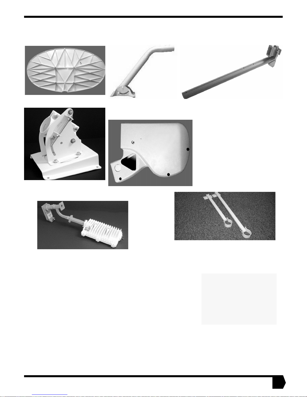
SATELLITE DISH KIT COMPONENTS
YOUR SATELLITE DISH KIT SHOULD INCLUDE THE FOLLOWING ITEMS:
Satellite Dis h (rear view)
Azimuth/Elevation Cap
Mast and Base
Plate
Shroud
Transmitter/Tria
Assembly
Feed Arm
Brace Kit
PARTS LIST
Your kit also contains assorted hardware, such as bolts, nuts, and other items. You may have hardware left over after you
finish installatio n.
• Allen scre ws , M 4 , Q ty : 4
• Lock washers, M4, Qty: 4
• Allen wrench, 3mm, Qty: 1
• Grounding bolt, 1/4-20 x 1/2-i nc h
• Red O-ring, Qty: 1
• Bolts, 5/16-18 x 1-1/2-inch, Qty: 2
• Wedge nut, 5/16-18, Qty: 1
• Hex-head bolt, 5/16-18 x 2-inch, Qty: 1
• Hex-head nut, 1/4-20, Qty: 1
• Galvanized washers, 3/8-inch Qty: 6
• Nylock nuts, 5/16-inch, Qty: 4
• Lag screw s, 1/4-inch x 4- inc h, Qty: 4
• Lag screw s, 3/8-inch x 4- inc h, Qty: 6
• Lag screw s, 3/8-inch x 2- inc h, Qty: 4
• Star washer, (toothed, for use with grounding), 1/4-inch, Qt y: 1
• Flat washer, 5/16-inch, Qty: 5
• Lock washers, 5/16-inch, Qty: 3
• Galvanized washers, 1/4-inch, Qty: 5
• Flat washers, narrow, 5/16-inch, Qty: 2
Also included are items that are
necessary to co nnect th e satellite dish and your computer.
See the installation guide that
comes with t he so ft ware kit and
indoor equipment (packaged
separately) for a complete list.
1
CON VENTIONS USED IN THIS GUIDE
The following conventions are used throughout this guide to h elp you become familiar with possible safety and equipment hazards.
This safe ty al ert symbol is us ed to a lert you to hazards or
hazardous situ ations that can res ul t in personal injury. A
signal word,
with the alert symbol to indicate the likelihood and
potential se verity of injury.
DANGER
Indicates an immine nt haza rd or unsa f e pr actic e whic h, if
not avoided, will result in death or severe personal injury .
WARNING
Indicates a hazard or unsafe practice which, if not
avoided, could result in death or severe personal injury.
DANGER, WARNING
CAUTION
, or
, is used
CAUTION
Indicates a hazard or unsafe practice which, if not
avoided, might result in moderate or minor personal injury.
CAUTION
When used without the alert symbol, indicates a hazard or
unsafe pr a ctic e that might result in property damage.
Note: A note pr esents ad ditional informati on.
2

INTRODUCTION
If you have not yet arranged for profe ssional install ation, con tact your dealer, or call 1-866-347-3292, for information on
having your system installed by an authorized professional
installer.
WARNING
Professional installation or service of your two-way
satellite dish i s re q uire d by the Fede r a l C ommunications
Commission because the radio transmits radio frequency
energy.
CAUTION
The two-way satellite dish must be installed in a lo ca tio n
or manner not readily accessib le to ch ildren an d at least 5
feet above ground level.
CAUTION
• This device emits radio frequency energy when in the
transmit mode.
• To avoid injury, do not place head or other body parts
between the feed horn and satellite dish when sy st em
is operational.
• Unplug indoor power connection before performing
maintenance or a dd ing u pg rades to any s ate llite dish
components.
This Satellite Dish Installation Guide Model: DW4000 TwoWay provides information required to assemble your satellite
dish and establish contact with the satellite.
OTHER USEFUL GUIDES
The installation guide included with the software and indoor
equipment gives an overview of the entire installation process,
including the modem and software installation.
WHAT IS INCLUDED IN THE SATELLITE BROADBAND SYSTEM
The satellite broadband system consists of several major components:
• The receive modem
• The transmit modem
• The satellite dish assembly that is installed outside
• Cables for connecting the modems and your computer
•Software
• This guide and the software and indoor equipment installation guide
This guide is intended for an installer experienced in p erforming the various installation tasks. The ins taller may be required
to:
• Use a power drill to drill holes i nt o your h ouse.
• Locate rafters or trusses and drill holes in the exact center of
them.
• Determine whether there are water pipes, electrical wiring, or
gas lines hidden in the walls near where you will be dril ling.
• Route coaxial cable through the foundation wall , under
floors, and through interior walls.
• Ground the satellite dish and coaxial cable as recommended
in the National Electrical Code (published by the National
Fire Protection Association, Batterymarch Park, Quincy, MA
02269).
Contact your dealer, or call 1-866-347-3292, for information
on having your system installed by an authorized professional
installer.
INSTALLATION AND YOUR HOME
The Federal Communications Commission (FCC) has a rule
that generally forbids local governments and homeowners
associations from preventing installation of DBS dishes one
meter or smaller in size (in Alaska, the dish size limit does not
apply). For more information, please visit the FCC’s Web site
at www.fcc.gov. Use the site search engine to find the FCC
F a ct Sheet on Pl acement of Ant ennas .
BASIC STEPS OF SATELLITE DISH INSTALLATION
Your installer will follow these basic steps:
1. Use a laptop computer t o determine ant enna p ointing values
for your satellite dish
2. Choose an installation site
3. Select a mounting method
4. Install the m ount
5. Assemble the satellite dish
6. Install the sa tell ite di sh o n th e mount
7. Run cable and ground wire t o connect and grou nd t he entire
assembly
8. Aim the satellite dish
9. Install the software on your computer and connect the satellite modems to your computer
3
INSTALLING SOFTWARE AND LOCATING THE SATELLITE
Before you can install the satellite dish, you must select an installation site. Before you can select an installation s ite, you must determine the direction you will aim the satellite dish. The installer will use information on a laptop computer to determine the direction.
The satellite is located approximately 22,300 miles in geostationary orbit above the equator. The satellite travels above Earth’s equator from west to east at a speed matching that of Earth’s rotation, thus appearing stati onary in relati on to th e Earth’s surface. To aim
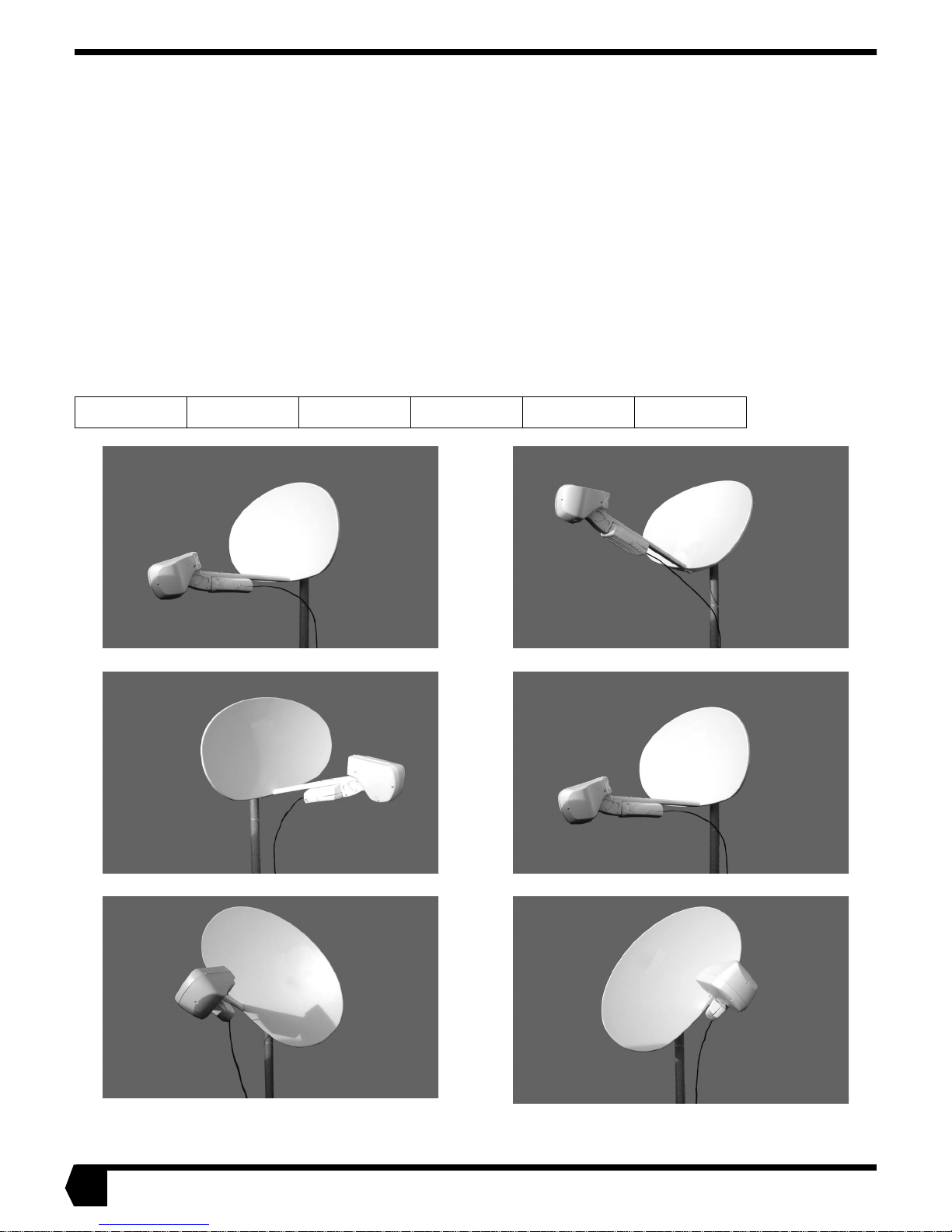
the satellite dish at the satellite, you need to kno w the azimuth, ele vation, and polarization angles. As sho wn in the f igures belo w, you
set the satellite dish to the correct azimuth angle by turning it from side to side, and set the elevation by tilting the satellite dish up or
down. You set the polarization by rotating the satellite dish. The polarization setting rotates the satellite dish to the correct orientation
for your geographic location. This varies from one part of the country to another and is different for different satellites. Polarization
is positive in the eastern United States and negative in the western United States. Remember that it is important to pay attention to
positive ( +) and negative (-) signs w hen record in g and using antenn a poi nting values.
Before you install the satellite dish, the receive modem and software must be installed. To install the software, see the software and
indoor equipment installation guide for specific instructions. After you install the modem and software, run the software program. It
will take you to an Antenna P ointing screen, where you will be asked to enter your location or zip code. The software will provide the
azimuth, elevation, and polarization angles. Write them below. The pictures below will help you visualize these terms.
Elevation: Azimuth: Polarization:
Elevation Down
Azimuth Left
Elevation Up
Azimuth Right
4
Polarization
Negative
Polarization
Positive
CHOOSING WHERE TO INSTALL THE SATELLITE DISH
TOOLS NEEDED
• Hand-held magnetic compass
• Angle finder or protractor
• Carpenter’s level or straight edge
CAUTION
• Peopl e c an trip , fall into or othe rwise b ump into th e sat ellite dish.
• Lacerations, bruises, or other impact injuries could
occur .
• Choose an installation site away from where people
are likely to work, ride, or play.
Perform the following steps to select the best site to install the
satellite dish:
1. Go to the location where you plan to install the satellite
dish. This should be the shortest distance possible from
where you have installed your computer. If the total receive
cable length is greater than 150 feet see the cabl e spe cifications on page 7.
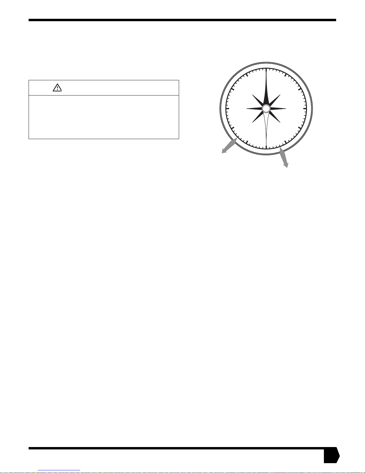
2. Face the south and hold the compass level so the needle can
rotate freely. When the needle stops rotating, it will be
pointing north. Carefully, so as not to disturb the needle,
rotate the body of the compass so that the 0° or N mark
printed on the compass aligns with the painted end of the
needle. The compass is now aligned with magnetic north.
Note: Metal near the compass may affect your reading. If you are
standing near a meta l structure, such as a shed or air conditioning
unit, move several feet away and repeat the measurement. Holding the
compass too close to a large metal belt buckle can have the sam e
effect.
3. Draw an imaginary line from the center of the compass to
the azimuth value you recorded on page 4. This is the direction to point the satellite dish. Use a rock or some other
object to mark the location where you are standing. Then
pick a landmark in the distance that aligns with the magnetic azimuth bearing, or mark the azimuth direction in
some other way.
.
300
270
Example 1
225° Azimuth
240
330
NW
W
210
Figure 1
SW
0
N
S
180
Example 2
160° Azimuth
NE
30
SE
E
150
60
90
120
5
CHOOSING WHERE TO INSTALL THE SATELLITE DISH
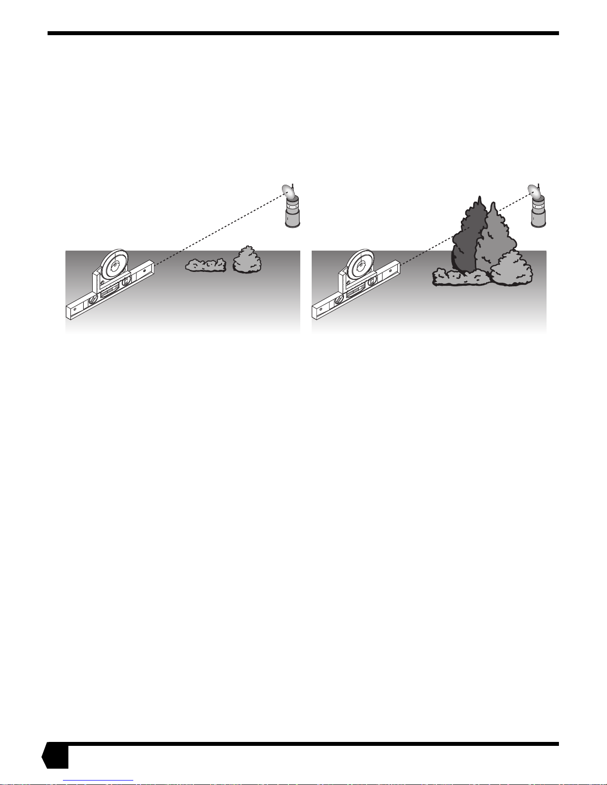
4. Using the angle finder and a carpenter’s level or straight
edge, verify that there is an unobstructed line-of-sight
toward the satellite as shown in the diagram b elow. To do
this, align the level along the azimuth bea ring. Then, using
the angle finder, lift the front end of the straight edge to correspond to the elevation angl e you recorded on page 4. Sight
along the straight edge to verify that there are no obstruc-
Good View
(Clear line-of-sight, no
obstructions in the way)
4
5
0
90
45
4
5
90
2 1
0
5
4
3
2
1
Figure 2
tions (such as buildings or trees) blocking the view. Take
into account future tree growth; if you install during the fall
or winter, account for spring and s ummer leaf growth. Also,
avoid installing the satellite dish next to electrical equipment such as air-conditioning units, because they can cause
signal interference.
Poor View
(Obstructed line-ofsight, trees are blocking the signal)
4
5
0
90
45
4
5
90
2 1
0
5
4
3
2
1
6
CABLE SPECIFICATIONS
Note: Coaxial cables with copper clad steel center conductor are not recommended.
Note: Do not use splitters.
Note: Line amplifiers are required for Receive cable runs of more than 150 ft.
Note: The grounding scheme you choose may affect your choice of cable; see “Overview of Grounding the Satellite System” on
page 29.
Use plenum grade cable only if the cable is to be run in plenum space which is carrying return air for the air circulation system, or
when local laws require it.
If the Receive cable run length is less than 150 ft., then no line amplifier is required. If the Receive cable run length is greater than
150 ft., but less than 300 ft., then install a line amplifier in the Receive cable only, at a minimum of 25 ft. and up to 30 ft. from the
LNB.
A line amplifier, if needed, can be installed only in the Receive cable, not in the Transmit cable.
Line amplifier specification: Channel Master 5113 IF D or equivalent.
Grounding and Cable Choice
Your choice of grounding scheme may affect your choice of cable;
Grounding the Sa tellit e System” on pa ge 29
meeting the National Electrical Code grounding requirements is easier if you use RG-6 with
solid copper center conductor and quad shield. How ever, y o u can als o meet the
requirements by using RG-6 with solid copper center conductor only and g rounding the
mast as described in the Overview.
for information about grounding. Note that
see “Overview of
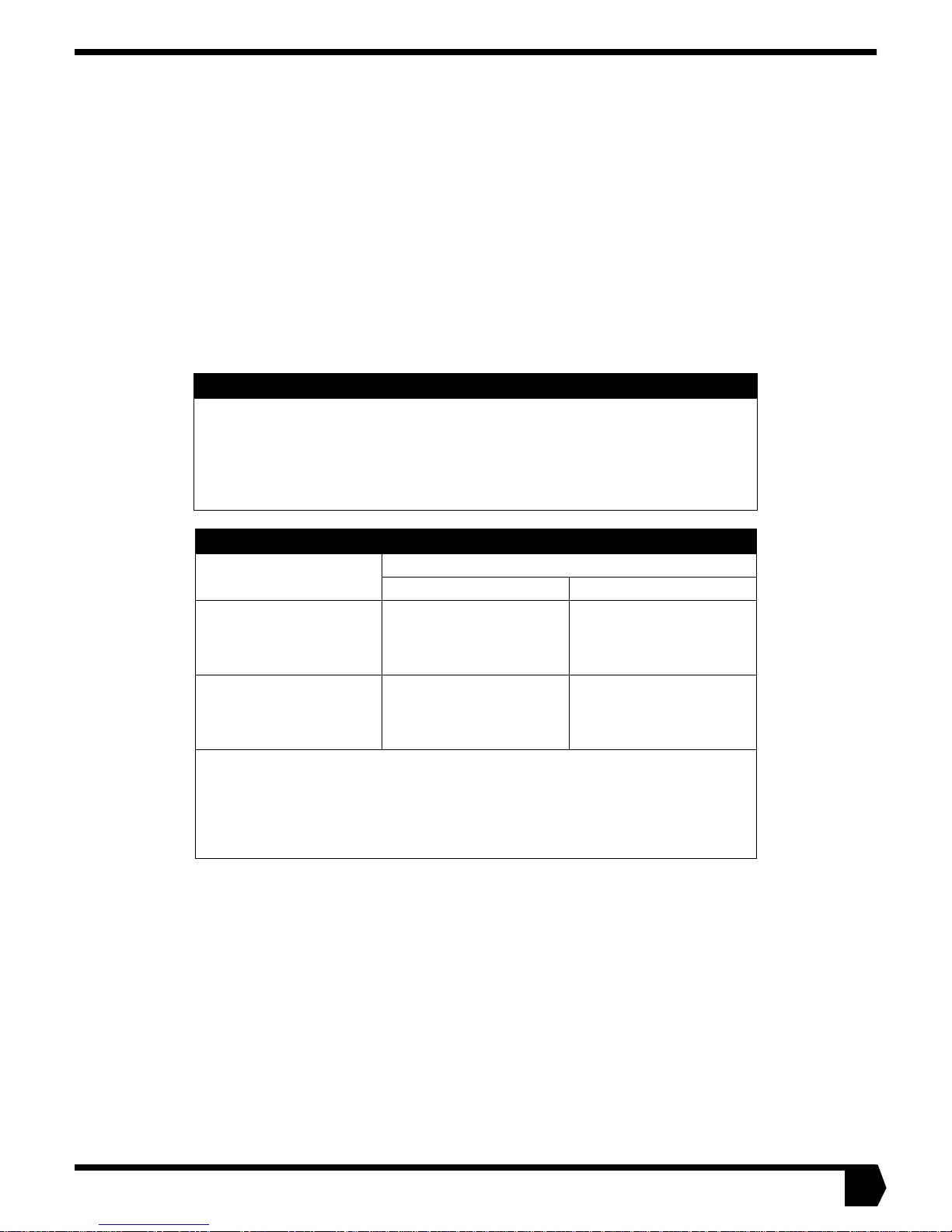
Recommended cable specifications for One-Way and Two-Way Systems
Cable length from sat ellite
dish to computer
Up to 300 ft. RG6 with solid copper
300 ft. to 420 ft. RG6 with solid copper
Important: A higher gra de of cab l e can be used f o r an inst allati on whe re a lo w er gr ade is
specified. Fo r exa mple , an RG6 cab le with sol id copper cent er conducto r and quad shiel d
can be used for installations w here th e c able length is less th an 300 ft. Never use a lower
grade of cable than specified. Be sure to record the grade of the cable used for your
installation. The grade is printed on the cable every few feet. Never use a cable which
does not have the manufacturers name and its grade clearly printed on it!
Type of cable to be used
Receive Transmit
RG6 with solid copper
center conductor
(CommScope 5729 or
equivalent)
center conductor
(CommScope 5729 or
equivalent)
center conductor
(CommScope 5729 or
equivalent)
RG6 with solid copper
center conductor and quad
shield (CommScope 5781
or equivalent)
7
SELECTING A MOUNTING OPTION
2
/
Based on the satellite dish installation site, decide on th e best
surface for mounting your satellite dish. The base plate and
mast assembly that came with your satellite dish is called a uni-
versal mount. Some mounting options require only the universal mount. Other mounting options requ ire that you also use
the two struts (called a brace kit) that came assembled with
your satellite dish kit. The struts slip over the mast and provide
additional support.
CAUTION
• Before installing the universal mount brace kit, you
should obtain an analysis from a structural engineer to
confirm that the install ation site is sui table f or mou nting
your satellite d ish using the bra ce kit .
• Failure to ensure that the installation site is capable of
supporting the weigh t o f th e satellite dish coul d res ult
in personal injury or property damage.
CAUTION
The satellite dish shou ld no t be ins ta lled o n a wo od fr ame
roof unless the roo f interior is unfinished so th at
placement of lag screws can be verified and the interior
reinforc ed if n ec es sa ry.
INSTALLING THE SATELLITE DISH ON A WOOD DECK POST
You can use the univ ersal mount to install the satellite dish on a
6-inch x 6-inch Southern Pine wood deck post.
See “Installing The Mount on a Wooden Deck Post” on
page 10.
G-
12
Figure 3
CAUTION
The satellite dish m ust be installed in a location or man ner
not readily accessible to children and at least 5 feet above
ground level.
Note: Installers must:
• F ollow the in structions in this manual pr e cisely
• Install the satellite dish no higher than 30 feet above grade
• Install the satellite dish only on approved surfaces, and NOT on
any other surfaces
• If necessary, be able to locate wood memb ers
• If necessary, install la g scr e ws in the cen ter of wood memb ers
INSTALLING THE SATELLITE DISH ON TYPICAL WOOD
FRAMED ROOF CONSTRUCTION
You can use the universal mount and brace kit to install the satellite dish on typical wood framed roof construction.
See “Installing the Mount on a Wood Framed Roof” on
page 13.
Figure 4
8
SELECTING A MOUNTING OPTION
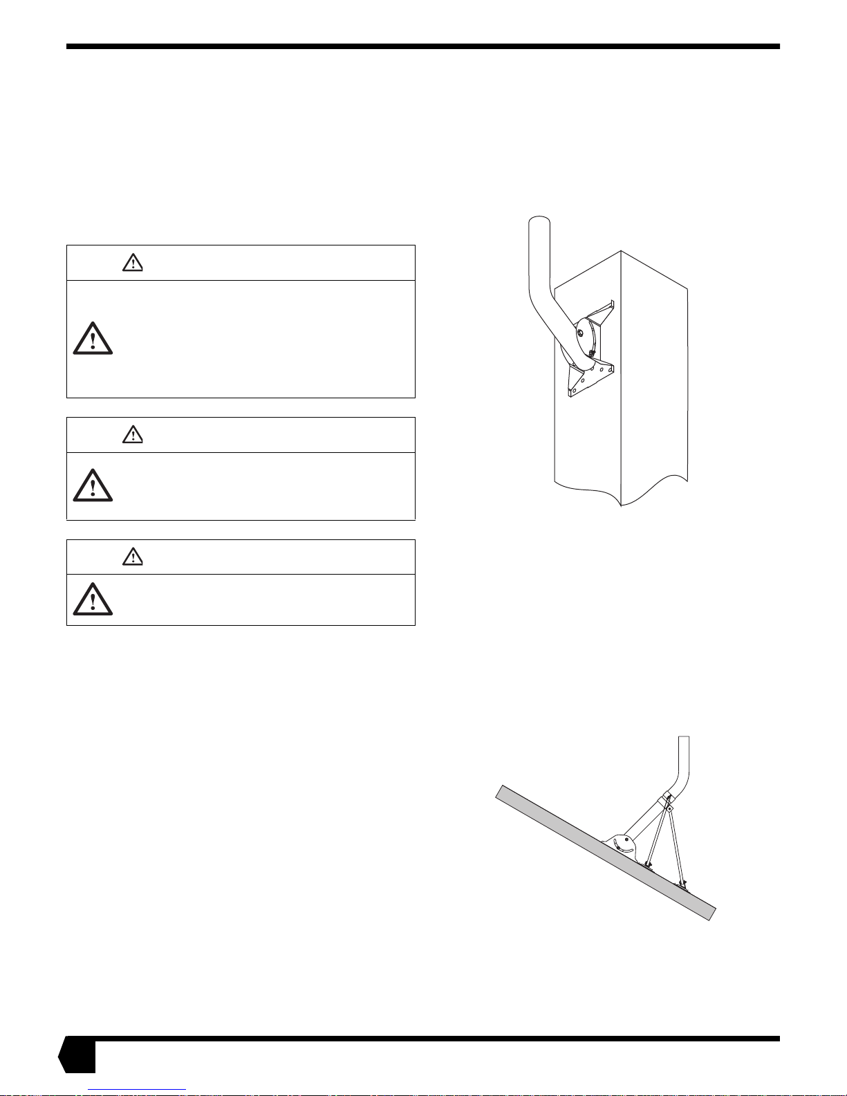
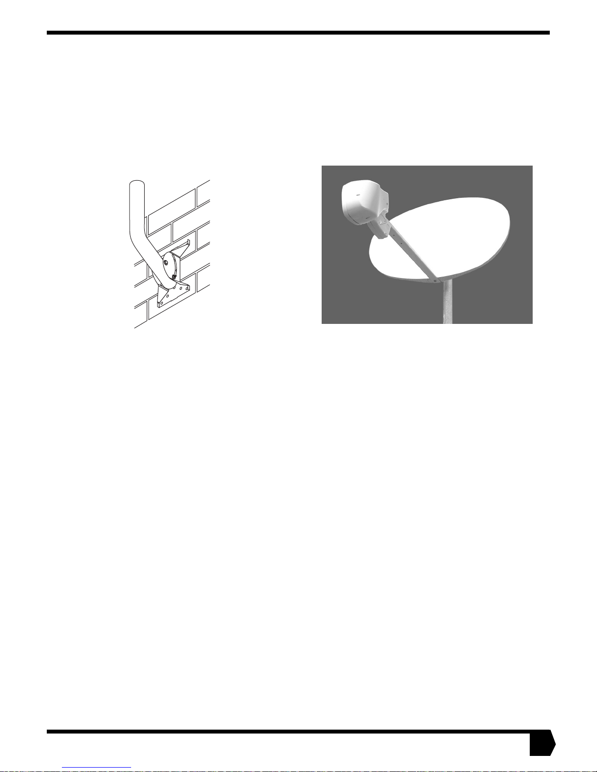
INSTALLING THE SATELLITE DISH ON CONCRETE OR CONCRETE MASONRY WALLS
You can use the universal mount to install the satellite dish on
concrete masonry or concrete walls. The brace kit can also be
installed for greater stability, but is not required.
See “Installing the Mount on Concrete or Concrete
Masonry Walls” on page 18.
Figure 5
INSTALLING THE SATELLITE DISH ON A METAL POLE
You can install the satellite dish directly on an 9-foot metal
pole. If you choose this mount option you will not need the
universal mount or universal mount brace kit. Store them for
possible future use.
See “Installing the Mount Onto a Metal Pole” on page 20.
Figure 6
9
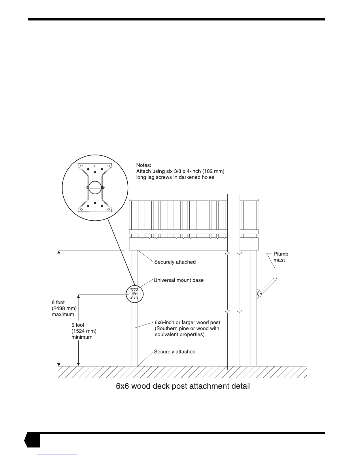
INSTALLING THE MOUNT ON A WOODEN DECK POST
The satellite dish can be installed on a 6-inch x 6-inch Southern Pine wood deck support post. The post can be no more than 8 feet
tall. It must be securely attached at top and bottom. Posts made of other species of wood may be used as long as their material properties match or exceed those of Southern Pine. Posts made of other species of wood whose material properties do not match or
exceed those of Southern Pine require engineering evaluation and approv al before bei ng u sed. The satelli te dis h may not be i nstalled
on an unsupported wooden po st.
PARTS NEEDED TOOLS NEEDED
• Lag scre w s , 3/8-inch x 4-inc h, Q t y: 6
• Wa sh ers, 3/8-inch, Qty: 6
• Silicone seala nt
• Carpenter’s lev el
• Pe ncil
• Ruler
• 9/16 and 1/2 -in ch socket wr ench
• Electric drill
• Drill bits, 3/8-inch, 1/4-inch, and 1/8-inch
• Torque wrench
up to 18 ft-lbs)
• Ladder
(capabl e o f t orq ui ng
10
Figure 7
INSTALLING THE MAST ONTO A W OODEN DEC K POST
4
0
INSTALLATION PROCEDURE
DANGER
• If the satellite d is h c on ta cts electric power line s, you
will be killed or s eriou sly injured.
• Before starting the installation procedure, make sure
there are no power lines nearby.
CAUTION
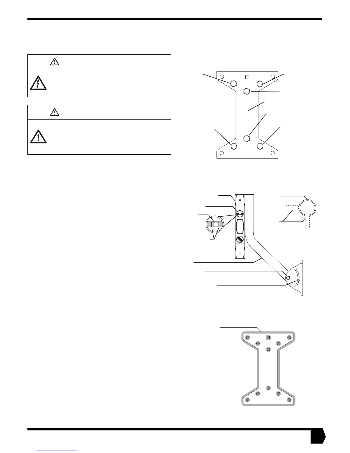
Top left center
All lag screws
3/8-inches x 4-inches
Top
Top right center
Top center
Center line
Bottom center
• The satellite dish cannot be installed on an unsupported wood post of any size.
• Install the sate llite dish only on a w o oden deck post.
• Install the sate llite dish only as des cribe d in th is man-
ual.
Note: for an installation to be successful, the mast must be plumb. Replumb the mast wheneve r in str ucted to do so, an d re-plumb it whenever you feel it is necessary .
1. Orient the universal mount so the square hole in the base
plate is at the top as in Figure 8 before installation.
2. Use a 1/2-inch socket wrench to loosen the adjustment nuts
and swing the mast so that it is oriented as in Figure 9.
3. Mark the centerline of the deck post.
4. W ith an assistant place the base plate on the centerline at the
spot you plan to install it (see Figur e 8).
5. Loosen the pi vo t bolt nut and adjustment nuts and plumb the
mast in two perpendicular directions (see Figure 9). If you
successfully plumb the mast tighten the nuts and proceed to
step 6. If you cannot plumb the mast find another location to
install the satellite dish. Note: it is essential that the mast be
plumb. If you cannot make t he mast pl umb at this poi nt , find
another installation s i te .
6. Mark the center of the base plate’s top center hole.
7. Drill a hole on the center mark in the manner described
below. Note: to avoid drilling too deeply, wrap a piece of
masking tape around the drill bit shank at the proper depth
so that you can see when you should stop d ri lling.
Drill a 1/8-inch pilot hole 2 inches deep.
Going into the pilot hole, drill a 1/4-inch hole 4 inches deep.
Going into the 1/4-inch hole, drill a 3/8-inch hole to a depth
equal to the unthreaded portion of the 3/8-inch x 4-inch lag
screw.
8. Fill the holes with silicone sealant and apply silicone sealant
to the entire back side of the base plate. Apply enough so
that it will press out around the edges when the plate is fastened down (see Figure 10).
Bottom left center
Carpenter's level
Plumb vial
Bubble
Bubble must
be centered
between
marks
Mast
Pivot bolt
Adjustment nut
(2 places)
Sealant
Bottom
Figure 8
Figure 9
Mast
(top view)
Level
Bottom right
center
G-218
11/16/
Figure 10
11
 Loading...