

Hughes BGAN Installation Manual
Installing the Hughes BGAN Remote Antenna
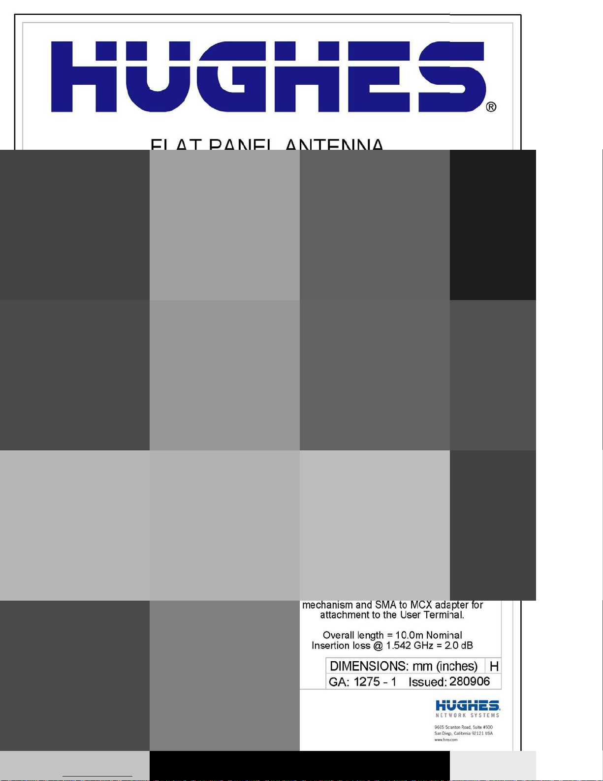
Product description – BGAN Remote Antenna
The Hughes BGAN Remote Antenna (HNS Part No. 9501286-0001) is designed to be permanently installed with the
Basic Fixed Mount Kit (HNS part number 3004066-0002).
Important Notes:
• The Hughes BGAN Remote Antenna and its cable assembly are designed for a one-time permanent
installation. If the Remote Antenna is decommissioned, then the RF cable must be replaced with a new
cable before the antenna is reinstalled at the same or a different location.
• The cable assembly supplied (10.0m), forms an integral part of the antenna system and is made to a
specific length in order to meet the system specifications. The cable must not be cut to a shorter length,
nor must cables be added to the cable run.
• It is essential that only the supplied cable is used. Third party cables may not be used; their use will
invalidate the warranty of the antenna and may cause system malfunction.
The BGAN Remote Antenna kit primarily consists of the antenna and cable for connection to the BGAN satellite
modem terminal. All necessary fixings are included.
Installation Instructions
Step 1: Inspecting the parts
Make sure you have all parts listed on the shipment box before beginning the installation; you should have the
following parts:
1. Flat panel antenna
2. 10m coaxial cable terminating in N(M) and SMA(M) connectors
3. Strain relief adapter
4. Cable retaining clips
5. ¼” UNC nuts
6. Self-amalgamating tape
7. Zip strap
Step 2: Determining where to install the terminal
In order for your terminal to work correctly, it must be installed in a location that provides a clear, unobstructed, line of
sight between the terminal and the satellite. Any objects such as building structures or trees may degrade the quality
of the satellite to terminal connection. To determine where to install the BGAN remote antenna, you need to
determine that you have both a clear unobstructed line of sight to the satellite and that your fixed mount is aimed in
the approximate direction to the satellite.
To determine the direction from your location to the satellite follow the steps below:
1. Unpack the Hughes 9201 BGAN Satellite Modem and connect it to a Personal Computer or Mac that
has the LaunchPad MMI Software installed. Follow the instructions in the Hughes 9201 user guide.
2. Power up the Hughes 9201 and launch the LaunchPad Software.
3. After LaunchPad connected successfully to the Hughes 9201 it shows the coverage map of the BGAN
system. Click on the map to identify your approximate position. Figure 1 shows an example.
4. LaunchPad now indicates elevation angle and compass direction of the available BGAN satellite(s) for
your location.
5. Use the antenna pointing mode of the Hughes 9201 to verify that you can obtain the BGAN satellite
signal from the location where the Remote Antenna is to be installed.
HUGHES is a registered trademark of Hughes Network Systems, LLC. Hughes Network Systems, LLC
All other trademarks are the property of their respective owners. 11717 Exploration Lane Germantown, MD 20876 USA
© 2010 Hughes Network Systems, LLC. All rights reserved.
All information is subject to change.
bgan.hughes.com
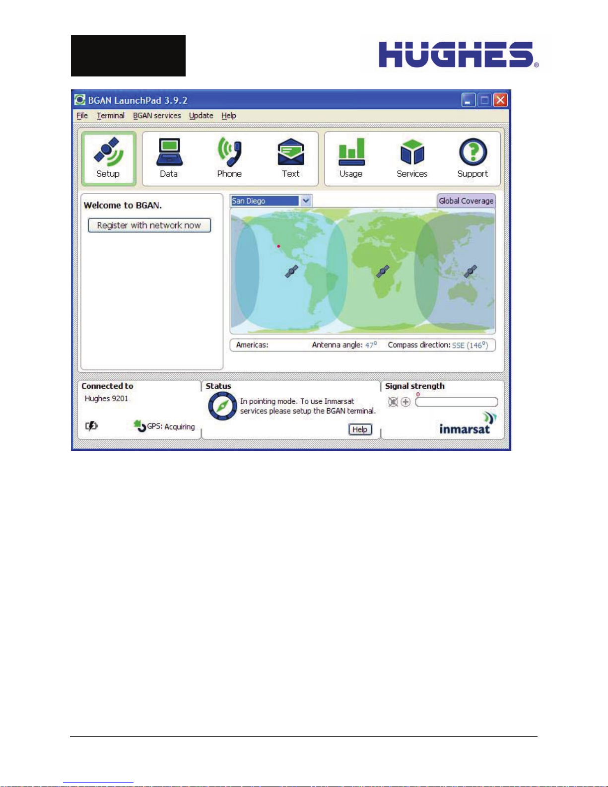
Figure 1 - LaunchPad Setup screen showing the recommended antenna pointing angle
Step 3: Mounting the pole base bracket
You may install the fixed mount on any structurally sound surface; either on a horizontal, or vertical, or a sloped
surface such as a roof or wall.
The pole is shipped attached to the base bracket. Mount the base bracket of this assembly to the structure with the
appropriate hardware (not included). Once the base bracket is mounted, perform the following steps:
1. Insert the bubble level (figure 3) into the end of the pole (pipe) opposite the base bracket. The bubble
level fits inside the pole.
2. Loosen the pole attachment fasteners at the base bracket so the pole can swivel (figure 2).
3. Swivel the pole until the end of the pole where BGAN Remote Antenna will be installed is vertical (as
shown in Figure 4). Adjust the pipe position until the bubble is centered inside the circles on the top
surface of the bubble level as shown in figure 3.
4. Tighten the pole attachment fasteners on the base bracket (figure 2).
HUGHES is a registered trademark of Hughes Network Systems, LLC. Hughes Network Systems, LLC
All other trademarks are the property of their respective owners. 11717 Exploration Lane Germantown, MD 20876 USA
© 2010 Hughes Network Systems, LLC. All rights reserved.
All information is subject to change.
bgan.hughes.com
 Loading...