

Hughes AN9-074-G Installation Manual

0.74 m Antenna
1039384-0001
11717 Exploration Lane, Germantown, MD 20876
Installation Guide
Model AN9-074-G
Revision C
July 24, 2015
Phone (301) 428-5500 Fax (301) 428-1868/2830

Copyright © 2013-2015 Hughes Network Systems, LLC
All rights reserved. This publication and its contents are proprietary to Hughes Network
Systems, LLC. No part of this publication may be reproduced in any form or by any means
the written permission of Hughes Network Systems, LLC, 11717 Exploration Lane,
Hughes Network Systems, LLC has made every effort to ensure the correctness and
notice. Hughes Network Systems, LLC makes no warranty of any kind with regard to this
without
Germantown, Maryland 20876.
completeness of the material in this document. Hughes Network Systems, LLC shall not be liable
for errors contained herein. The information in this document is subject to change without
material, including, but not limited to, the implied warranties of merchantability and fitness for
a particular purpose.
Trademarks
HUGHES and Hughes Network Systems are trademarks of Hughes Network Systems, LLC. All
other trademarks are the property of their respective owners.

Contents
Understanding safety alert messages .................................................... 5
Messages concerning personal injury .................................................................... 5
Messages concerning property damage ................................................................ 5
Safety symbols ....................................................................................................... 6
Additional symbols ........................................................................................... 6
Antenna installation safety .................................................................... 7
Chapter 1
Overview ............................................................................................... 11
Model AN9-074-G antenna description ............................................................... 11
Antenna installation summary ............................................................................. 12
Approved cables .................................................................................................. 14
Chapter 2
Antenna parts and recommended tools ............................................... 15
Antenna kit components ..................................................................................... 15
Az/El mount assembly .................................................................................... 16
Reflector bracket and tilt plate ....................................................................... 17
Antenna reflector ........................................................................................... 18
Feed support arm ........................................................................................... 18
Radio assembly ............................................................................................... 19
Small hardware parts list ..................................................................................... 19
Tools ..................................................................................................................... 20
Chapter 3
Installing the antenna and radio .......................................................... 21
General instructions for assembling the antenna ............................................... 21
Select the installation site .................................................................................... 22
Install the satellite modem .................................................................................. 23
Determining the pointing values and polarization setting .................................. 23
Pointing values................................................................................................ 23
Polarization setting ......................................................................................... 23
Install the antenna mount ................................................................................... 23
Installing the reflector bracket and tilt plate ....................................................... 25
Installing the antenna reflector ........................................................................... 26
Installing the feed support arm ........................................................................... 28
Installing the radio assembly ............................................................................... 29
Changing transmit circular polarization (if needed) ....................................... 31
Installing the antenna assembly onto the mast .................................................. 33
Chapter 4
Cabling, connections, and grounding ................................................... 35
Cabling requirements .......................................................................................... 35
Routing the IFL cable at the antenna ................................................................... 36
Connecting the IFL cable ...................................................................................... 37
Contents
1039384-0001 Revision C
3

Ground connections ............................................................................................ 38
Antenna mast ................................................................................................. 38
Radio ............................................................................................................... 38
Pointing ................................................................................................................ 38
Chapter 5
Adjusting antenna azimuth and elevation ........................................... 39
Adjusting azimuth ................................................................................................ 39
Checking the azimuth base starting position ................................................. 40
Coarse azimuth adjustment ............................................................................ 41
Fine azimuth adjustment ................................................................................ 41
Adjusting elevation .............................................................................................. 42
Weatherproof the cable connections .................................................................. 43
Index .................................................................................................... 45
Contents
4
1039384-0001 Revision C
DANGER indicates a potentially hazardous situation which, if not avoided, will
result
WARNING indicates a potentially hazardous situation which, if not avoided,
could
CAUTION indicates a potentially hazardous situation which, if not avoided,
could
NOTICE is used for advisory messages concerning possible property damage,
product
personal
Understanding safety alert messages
Safety alert messages call attention to potential safety hazards and tell you how to
avoid them. These messages are identified by the signal words DANGER, WARNING,
CAUTION, or NOTICE, as illustrated below. To avoid possible property damage,
personal injury, or in some cases possible death, read and comply with all safety
alert messages.
Messages concerning personal injury
The signal words DANGER, WARNING, and CAUTION indicate hazards that could
result in personal injury or in some cases death, as explained below. Each of these
signal words indicates the severity of the potential hazard.
in death or serious injury.
result in death or serious injury.
result in minor or moderate injury.
Messages concerning property damage
A NOTICE concerns property damage only.
damage or malfunction, data loss, or other unwanted results—but not
injury.
Understanding safety alert messages
1039384-0001 Revision C
5
Indicates a safety message that concerns a potential electric
Indicates a safety message that concerns a potentially
Indicates a safety message that concerns radio frequency (RF)
Safety symbols
Additional symbols
The generic safety alert symbol
calls attention to a potential personal injury hazard. It appears next to the DANGER,
WARNING, and CAUTION signal words as part of the signal word label. Other
symbols may appear next to DANGER, WARNING, or CAUTION to indicate a specific
type of hazard (for example, fire, or electric shock). If other hazard symbols are used
in this document they are identified in this section.
This document uses the following hazard symbols:
shock hazard.
hazardous situation in which you could fall.
energy.
Understanding safety alert messages
6
1039384-0001 Revision C
If you work on a roof, tower, or other high structure, or use a ladder or
scaffold
injury
• To avoid electric shock, stay at least 20 ft away from power lines when
If the antenna reflector contacts electric power lines,
Only Hughes-certified installers may install or service Hughes antennas and
their
requirements
Antenna installation safety
Observe the following precautions when installing the satellite antenna. This
manual also includes other safety alerts, where appropriate, concerning specific
installation procedures.
to access the work site, follow these precautions to prevent personal
or death:
• Walk only on sound roof structures.
• Make sure the antenna assembly and installation surface are structurally
sound so they can support all loads (equipment weight, ice, and wind).
• Use safety equipment (e.g., a lifeline) appropriate for the work location.
• Follow all manufacturer safety precautions for all safety and other
equipment used.
• Perform as many procedures as possible on the ground.
there is a chance that you or the equipment you are using could come
into contact with the power lines. Always look up and check for
overhead lines before moving a ladder.
• If any part of the antenna or mount assembly comes in contact with a
power line, call the local power company to remove it. Do not try to
remove it yourself.
you may be killed or seriously injured.
• For pole mount installations, be sure to obtain information regarding
underground utilities in the proposed location before digging.
• Call a local company that marks underground utility lines before digging
to avoid striking underground cables, pipes, or electric lines. Call 811
from anywhere in the United States to contact a local company that
does this. You can also visit http://call811.com/
• Striking or cutting underground cables, pipes, or electric lines can cause
personal injury or property damage.
.
components. Installers must expressly acknowledge the Hughes
for Hughes installations.
Antenna installation safety
1039384-0001 Revision C
7
• Do not work in high wind or rain, or if a storm, lightning, or other
Antennas that have been improperly installed or attached to an unstable
structure are susceptible to wind damage, which can be very serious or even
life threatening
full responsibility that the installation is structura
(weight, wind, and ice) and is properly sealed against leaks.
Properly ground the antenna assembly in accordance with all local and
national
Observe these precautions to avoid exposure to RF radiation, a potential
safety
adverse weather conditions are present or approaching.
• Do not attempt to assemble, move, or mount the antenna on a windy
day. Even a slight wind can unexpectedly create sudden strong forces on
the antenna surface.
to you and the customer. The installer and the dealer assume
lly sound to support all loads
electrical codes.
hazard:
• All antennas must carry an industry-standard and government-approved
Radiation Hazard Caution label on the feed support arm.
• The antenna must be installed in a location not readily accessible to
children and in a manner that prevents human exposure to potentially
harmful levels of radiation.
• Antennas mounted in the continental United States, Puerto Rico, or a
site with an elevation angle that is 30° or greater must be installed such
that the lower lip of the reflector is at least 4 ft 5 inches above any
surface upon which a person might be expected to stand, and 3 ft 3
inches from any opening (such as a door or window) in a building or
adjacent structure.
• Antennas mounted in Canada, Alaska, Hawaii, or with a less than 30°
elevation must be installed such that the lower lip of the reflector is at
least 5 ft above any surface upon which a person might be expected to
stand, and 3 ft 3 inches from any opening (such as a door or window) in
a building or adjacent structure.
Antenna installation safety
8
1039384-0001 Revision C
• The antenna must be mounted such that no object that could
7 inches of the
Failure
personal
Observe these precautions to avoid exposure to RF radiation, a potential
safety hazard:
•
All antennas
•
Failure to observe these cautions could result in injury to eyes or other
personal injury.
reasonably be expected to support a person is within 6 ft
edges of a cylindrical space that projects outward from the antenna
reflector toward the satellite and has the same diameter as the
reflector. For example, the antenna may not be installed in a place
where the path of the cylindrical space passes immediately above a
deck on a nearby property. This reduces the likelihood of a person being
exposed to RF radiation because they stood inside of or next to that
cylindrical space.
• If the above distance requirements cannot be met, the antenna must be
mounted in a controlled area inaccessible to the general public, such as
a fenced enclosure or on a roof.
• Fenced installations must have a locked entry, and the fenced area must
be large enough to protect the general public from exposure to
potentially harmful levels of radiation.
• Access to a roof installation in a commercial, industrial, or institutional
environment must be limited by a door or a permanently fastened
ladder that is locked to deny access to the general public.
• Fenced or roof installations in commercial, industrial, or institutional
environments must carry a Radiation Hazard Caution sign on the access
door, gate, or permanently mounted access ladder within plain sight of
anyone approaching the antenna from the front or sides of the
reflector.
• Once the transmitter becomes operational, maintain a safe distance; at
least 3 ft.
to observe these cautions could result in injury to the eyes or other
injury.
Do not remove the yellow caution label on the antenna system.
of any type or size must carry an industry standard and government
approved Radiation Hazard Caution label on the feed support arm.
A fenced or roof installation in a commercial, industrial, or institutional
environment must carry a Radiation Hazard Caution sign on the access door,
gate, or permanently mounted access ladder within plain sight of anyone
approaching the antenna from the front or sides of the reflector.
Antenna installation safety
1039384-0001 Revision C
9

If the antenna or mount assembly begins to fall during the installation, do not
attempt
to catch it. Move away and let it fall.
Note: Some installations may require additional precautions. See the appropriate
site preparation and mount installation guide for more information.
Antenna installation safety
10
1039384-0001 Revision C
Only Hughes-certified installers may install or service Hughes antennas and
their
requirements
Chapter 1
Overview
This installation guide explains how to assemble and install the Hughes AN9-074-G
0.74 m antenna. It is written for qualified installers who are familiar with satellite
antenna installation practices and are capable of properly applying the information
presented herein.
This chapter presents an overview of the AN9-074-G antenna, a summary of the
steps used to assemble and install the antenna, and supplemental information on
tasks related to antenna installation.
components. Installers must expressly acknowledge the Hughes
for Hughes installations.
Model AN9-074-G antenna description
The Hughes model AN9-074-G antenna is designed for Ka-band applications. Each
JUPITER antenna station consists of an antenna assembly and a satellite modem.
The satellite modem communicates with both the Jupiter satellite and the Network
Operations Center (NOC) by way of the antenna and radio assembly.
The antenna is connected to the satellite modem by way of a single-cable
intra-facility link (IFL) that carries both the transmit and receive signals.
Figure 1 on page 30 shows the AN9-074-G antenna – with radio assembly –
assembled and installed on a trimast mount.
Chapter 1 • Overview
1039384-0001 Revision C
11

Figure 1: Hughes model AN9-074-G 0.74 m satellite antenna
Task
For details, see...
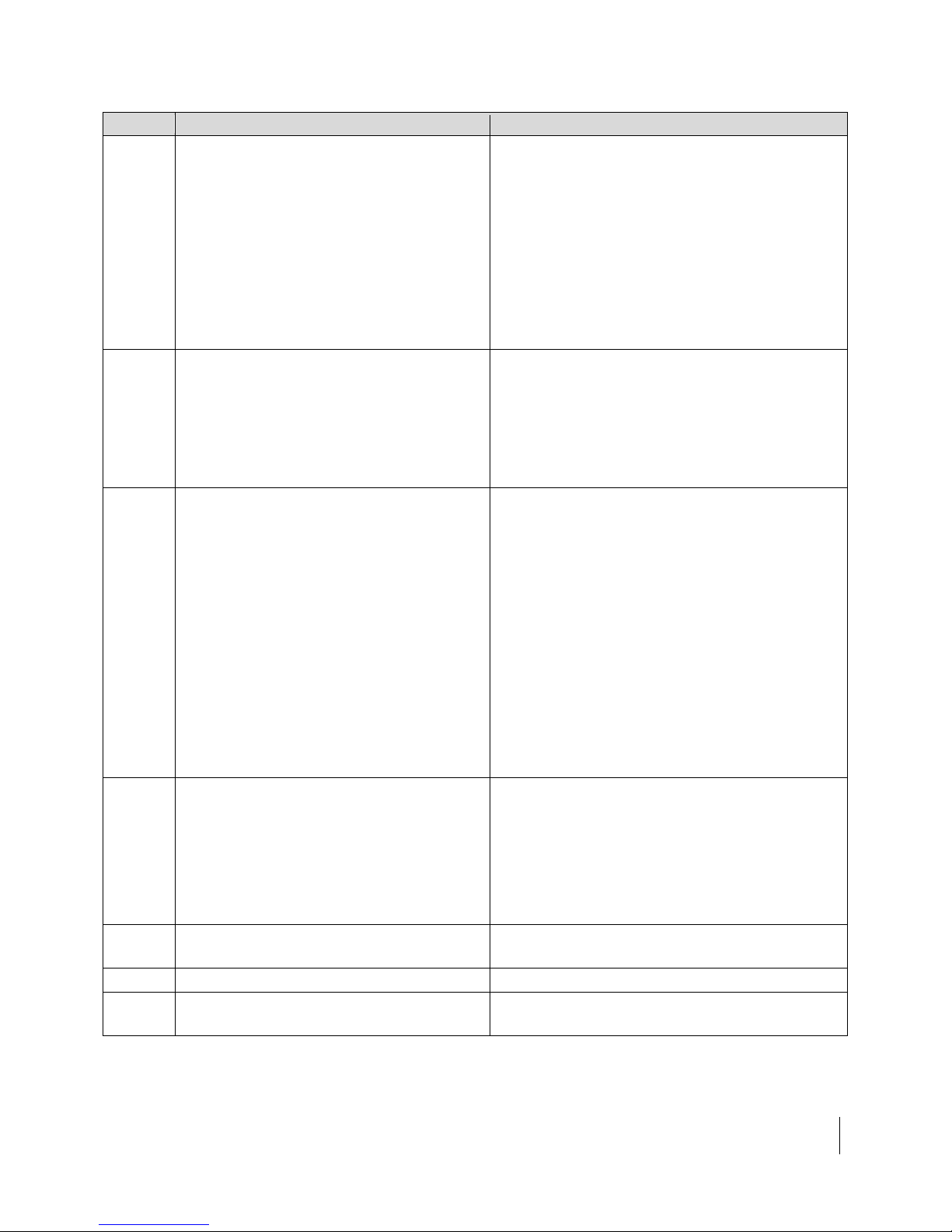
1
Explain the installation process to the
customer.
2
Conduct a site survey with the customer to
Select the installation site on page 22
installation guide
Antenna installation summary
Table 1 lists the basic steps and related tasks for assembling and installing the
antenna. Perform the procedures in the order listed. For detailed information on
each task, refer to the sections and/or other documents listed.
Table 1: Satellite antenna installation summary
identify a suitable location for the antenna.
Appropriate site preparation and mount
Chapter 1 • Overview
12
1039384-0001 Revision C
Task
For details, see...
3
Use Onsite Accelerated Service Installation
System (OASIS) app on your smart device to
elevation, and tilt).
JUPITER Antenna Pointing Guide (1039429-0001)
4
Install and apply power to the satellite
values (azimuth, elevation, and tilt).
Appropriate satellite modem installation guide
5
Proceed with the activation and
measurements.
JUPITER Antenna Pointing Guide (1039429-0001)
6
Determine the most suitable method for
Install the antenna mount on page 23
7
Assemble the antenna (Az/El mount, feed
support arm, reflector, and other parts).
Chapter 3 – Installing the antenna and radio
8
Install the radio assembly.
Installing the radio assembly on page 29
9
Install the antenna assembly on the mast.
Installing the antenna assembly onto the mast on
page 33
determine your best line of sight (LOS) before
installing your antenna, then take the required
pictures.
Once you have selected the best possible
location, download your GPS coordinates
within 15 m of the selected site to get the
exact settings for the pointing values (azimuth,
modem.
Note: You must install the satellite modem
before installing the antenna to
determine the proper antenna pointing
commissioning process in OASIS (use your
smart device to connect to the satellite
modem via the wireless router). Request site
latitude and longitude.
If you do not have a smart device, connect
your laptop to the satellite modem and enter
the coordinates from your GPS device when
prompted. Your GPS device must display
coordinates in a degrees/minutes/seconds
format, which is commonly found on devices
manufactured by Garmin, Magellan, etc. Some
phone or tablet GPS apps do not offer seconds
O
ASIS User Guide (1040630-0001)
O
ASIS User Guide (1040630-0001)
mounting the antenna, then install the
antenna mast.
N
ote: The antenna mast must be plumb. The
antenna cannot be adjusted to correct
for a mast that is not plumb.
A
ppropriate site preparation and mount installation
guide
Chapter 1 • Overview
1039384-0001 Revision C
13
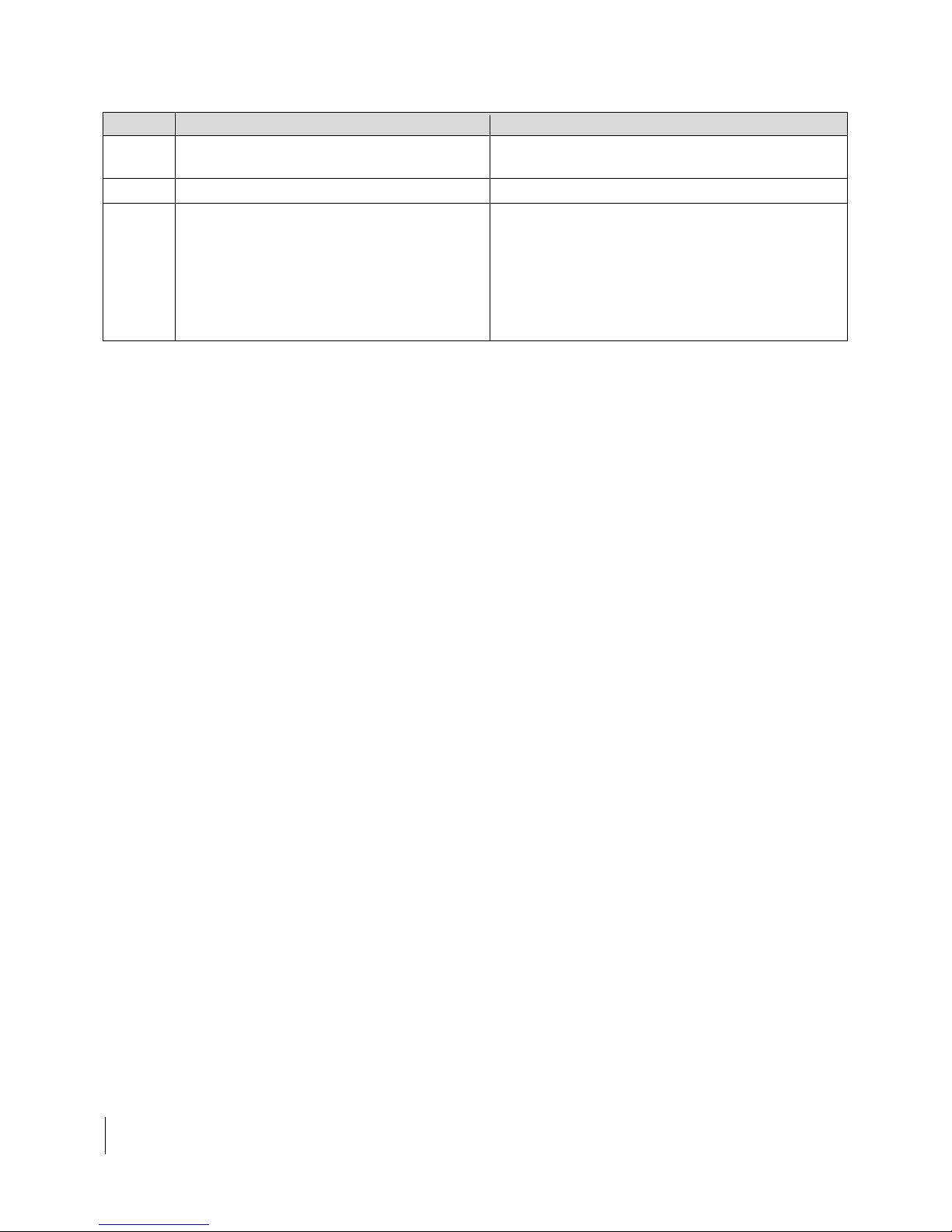
Task
For details, see...
10
Install the IFL cable between the satellite
modem and the antenna.
Chapter 4 – Cabling and connections
11
Ground the antenna assembly.
Ground connections on page 38
12
Point the antenna.
Mechanical adjustments for pointing:
OASIS User Guide (1040630-0001)
Once the antenna is properly pointed, you can commission the satellite modem as
instructed in the appropriate satellite modem installation guide.
Approved cables
For a list of approved coaxial cable types for the IFL between the antenna and the
satellite modem, see the Hughes FSB, IFL Cable, Approved List (with lengths) for
JUPITER/HTXXXX Domestic Installations (FSB 120909_01).
Chapter 5 – Adjusting antenna azimuth and elevation
Pointing procedure:
JUPITER Antenna Pointing Guide (1039429-0001)
The FSB lists the maximum cable length for each approved cable type.
Because it is impossible to predict the requirements specific to each installation site,
you must use your own judgment and best practices to determine how to route and
connect the IFL cable.
Chapter 1 • Overview
14
1039384-0001 Revision C
 Loading...