

Page 1

.98m Ka-Band Antenna
Installation Guide
Model: AN8-098R
1037752-0001
Revision A
June 17, 2008
Page 2

Revision record
Revision Date of issue Scope
A June 17, 2008 Production Release
Copyright © 2008 Hughes Network Systems, LLC
All rights reserved. This publication and its contents are propr ietary to Hughes Network Systems, LLC.
No part of this publication may be reproduced in any form or by any means without the written
permission of Hughes Network Systems, LLC, 11717 Exploration Lane, Germantown, Maryland 20876.
Hughes Network Systems, LLC has made every effort to ensure the correctness and complet
the material in this document. Hughes Network Systems, LLC shall not be liable for errors contained
herein. The information in this document is subject to change without notice. Hughes Network Systems,
LLC makes no warranty of any kind with regard to this material, including, but not limited to, the implied
warranties of merchantability and fitness for a particular purpose.
Hughes, HughesNet, Hughes Network Systems, and SPACEWAY are trademarks of Hughes Network
Systems, LLC. All other trademarks are the property of their respective owners. This product is
compatible with the Hughes SPACEWAY system.
eness of
Trademarks
Page 3
Important safety information
For your safety and protection, read this entire installation guide
before attempting to install the AN8-098R Ka-band antenna. In
particular, read this safety section carefully. Keep this safety
information where you can refer to it if necessary.
Types of warnings used
in this manual
This section introduces the various types of warnings used in this
manual to alert you to possible safety hazards.
DANGER
Indicates an imminently hazardous situation, which, if not
avoided, will result in death or serious injury.
WARNING
Indicates a potentially hazardous situation, which, if not
avoided, could result in death or serious injury.
CAUTION
Indicates a potentially hazardous situation, which, if not
avoided, may result in minor or moderate injury.
CAUTION
Indicates a situation or practice that might result in pr operty
damage.
• Important safety information
1037752-0001 Revision A
iii
Page 4

Product warning labels
The following safety alert labels are affixed to the antenna feed
support arms, radio transmitter, and antenna reflector,
respectively.
Feed support arm
Transmitter
• Important safety information
iv
1037752-0001 Revision A
Reflector (back side)
Safety alert labels on the antenna assembly
These labels advise that the antenna emits radio frequency (RF)
gy. Because of this potential safety hazard, observe all
ener
cautions on these labels and in the next section, Antenna
installation safety.
Page 5
Antenna installation
safety
Observe the following precautions when installing the antenna.
This manual also includes other safety alerts where appropriate
concerning specific installation procedures.
WARNING
Only Hughes-certified installers may install o r service
Hughes antennas and their components. Installers must
expressly acknowledge the Hughes requirements for
Hughes installations.
DANGER
If you work o n a roof, tower, or other high s tructure or use a
ladder or scaffold to access the work site, follow these
precautions to prevent personal injury or death:
• Walk onl y on sound roof structures.
• Mak
• Us
• Fol
• P
e sure the antenna assembly and installation
surface are structurally soun d so that they can support
all loads (equipment weight, ice, and wind).
e safety equipment (for example, a lifeline)
appropriate for the work location.
low all manufacturer saf e ty precaut ions for all safety
and other equipment used.
erform as many pr ocedure s as possib le on the ground.
DANGER
• To avoid electric shock, stay at least 20 ft from power
lines.
any part of the antenna or mount assembly co mes in
• If
contact with a power line, call the local power company
to remove it. Do not try to remove it yourself.
Failure to heed these warnings could result in serious injury
or death.
WARNING
Properly gr ound the antenna assembly according to all
federal and local electrical codes.
• Important safety information
1037752-0001 Revision A
v
Page 6
WARNING
• Do not work in high wind or ra in; or if a st orm, lightning,
or other adverse weather condit ions are either present
or approaching.
• Do not attempt to assemble, move, or mount the
antenna on a windy day. Even a slight wind can
unexpectedly creat e sudden strong f orces on the
antenna surface.
CAUTION
If the antenna or mount assembly begins to fall during the
installation, do not attempt to catch it. Move away and let it
fall.
WARNING
Antennas that have been impr oper ly insta lled or attac hed to
an unstable structure are suscepti ble to wind damage,
which can be very serious or even life threatening. The
product owner and installer ass ume full responsibility that
the installation is structurally sound to support all loads
(weight, wind, and ice) and i s properly sealed a ga inst leaks.
• Important safety information
vi
1037752-0001 Revision A
Page 7
CAUTION
Observe these precautions to avoid exposure to RF
radiation, a potential safety hazard:
antenna must be installed in a location not readily
• The
accessible to children and in a manner that prevents
human exposure to potentially harmful levels of
radiation.
tennas mounted in Puerto Rico, the continental
• An
United States, or at any sit e with a greater than 30°
elevation angle must be installed such that the lower lip
of the antenna reflector is at least 5 ft abo ve an y surface
upon which a person might be expected to stand, and
3 ft 3 inches f
window) in a building or adjacent structure.
tennas mounted in Canada, Alaska, Hawaii, or any
• An
site with a less than 30° elevation must be installed such
that the lower lip of the antenna reflector is at least
5 ft 9 inches above any surface upon which a per son
ht be expected to stand, and 3 ft 3 inches from any
mig
opening (such as a door or window) in a building or
adjacent structure.
antenna must be mounted such that no object t hat
• The
could reasonably be expected to support a person is
within 6 ft 7 inches of the edges of a cylindrical space
projecting outward from the antenna reflector towa rd
the satellite.
the above distance requirements cannot be met, the
• If
antenna must be mounted in a controlled area
inaccessible to the general public, such as a fenced
enclosure or a roof.
enced installation must have a locked entry, and the
• A f
fenced area must be lar ge enough to protect the general
public from exposure to potentially harmful levels of
radiation.
ccess to a roof installation in a commercial, industrial,
• A
or institutional envir onment m ust be limited b y a door or
a permanently fastened ladder that is locked to deny
access to the general public.
• Onc
e the transmitter becomes operational, maintain a
safe distance; at least 3 feet.
rom any opening (such as a door or
Failure to observe these cautions could result in injury to
yes or other personal injury.
e
• Important safety information
1037752-0001 Revision A
vii
Page 8
CAUTION
• All antennas of any type or size must carry an industry
standard and government approved Radiation Hazard
Caution label on the feed support arm.
• A fenced or roof inst al lati on i n a c ommercial, industrial,
or institutional environment must carry a Radiation
Hazard Caution sign on the access door, gate, or
permanently mounted access ladder within plain sight
of anyone approaching the antenna from the front or
sides of the reflector.
Failure to observe these cautions could result in injury to
yes or other personal injury.
e
Note: Some installations may require additional precautions. See
the HughesNet Antenna Site Preparation and Mount Installation
Guide (1035678-0001) for more information.
viii
• Important safety information
1037752-0001 Revision A
Page 9

Contents
Important safety information. . . . . . . . . . . . . . . . . . . . .iii
Types of warnings used in this manual . . . . . . . . . . . . . . . . . . . iii
Product warning labels. . . . . . . . . . . . . . . . . . . . . . . . . . . . . . . . iv
Antenna installation safety. . . . . . . . . . . . . . . . . . . . . . . . . . . . . .v
Chapter 1
Overview. . . . . . . . . . . . . . . . . . . . . . . . . . . . . . . . . . . . . . .1
The model AN8-098R antenna. . . . . . . . . . . . . . . . . . . . . . . . . . .1
Antenna installation summary . . . . . . . . . . . . . . . . . . . . . . . . . . .2
Tasks related to antenna installation . . . .
Selecting the installation site . . . . . . . . . . . . . . . . . . . . . . . . . .4
Installing the antenna mount . . . . . . . . . . . . . . . . . . . . . . . . . .4
Installing the satellite modem. . . . . . . . . . . . . . . . . . . . . . . . . .5
Grounding . . . . . . . . . . . . . . . . . . . . . . . . . . . . . . . . . . . . . . . . .5
Approved cables. . . . . . . . . . . . . . . . . . . . . . . . . . . . . . . . . . . .5
Chapter 2
Antenna parts and required tools. . . . . . . . . . . . . . . . . . .7
Antenna kit components. . . . . . . . . . . . . . . . . . . . . . . . . . . . . . . .7
Az/El mount assembly . . . . . . . . . . . . . . . . . . . . . . . . . . . . . . .9
Reflector bracket and tilt plate . . . . . . . . . . . . . . . . . . . . . . . .10
Antenna reflector . . . . . . . . . . . . . . . . . . . . . . . . . . . . . . . . . .10
Feed support arms and tailpiece. . . . . . . . . . . . . . . . . . . . . . .11
Radio assembly. . . . . . . . . . . . . . . . . . . . . . . . . . . . . . . . . . . .12
Feed horn and collar. . . . . . . . . . . . . . . . . . . . . . . . . . . . . . . .12
Elevation handle. . . . . . . . . . . . . . . . . . . . . . . . . . . . . . . . . . .13
Related Components. . . . . . . . . . . . . . . . . . . . . . . . . . . . . . . .13
Tri-mast (or other antenna mount) . . . . . . . . . . . . . . . . . . .13
Small hardware parts list . . . . . . . . . .
Tools. . . . . . . . . . . . . . . . . . . . . . . . . . . . . . . . . . . . . . . . . . . . . .15
. . . . . . . . . . . . . . . . . .4
. . . . . . . . . . . . . . . . . . . .14
Chapter 3
Installing the antenna and radio assembly . . . . . . . . . .17
Determining the pointing values . . . . . . . . . . . . . . . . . . . . . . . .17
General instructions for assembling the antenna
Installing the antenna reflector bracket and tilt plate. . . . . . . . .19
Installing the feed support arms and tailpiece . . . . . . . . . . . . . .20
Installing the antenna reflector. . . . . . . . . . . . . . . . . . . . . . . . . .22
1037752-0001 Revision A
. . . . . . . . . . . .18
• Contents
ix
Page 10

Installing the radio assembly . . . . . . . . . . . . . . . . . . . . . . . . . . .24
Adjusting transmit circular polarization. . . . . . . . . . . . . . . . .25
Installing the feed horn. . . . . . . . . . . . . . . . . . . . . . . . . . . . . . . .28
Installing the antenna assembly onto the mast
pipe . . . . . . . . . .30
Chapter 4
Cabling and connections . . . . . . . . . . . . . . . . . . . . . . . . .33
Cabling requirements . . . . . . . . . . . . . . . . . . . . . . . . . . . . . . . . .33
Routing the cables at the antenna. . . . . . .
Connecting the transmit and receive cables
Transmit cable . . . . . . . . . . . . . . . . . . . . . . . . . . . . . . . . . . . .36
Receive cable . . . . . . . . . . . . . . . . . . . . . . . . . . . . . . . . . . . . .3 7
Ground connections . . . . . . . . . . . . . . . . . . . . . . . . . . . . . . . . . .38
. . . . . . . . . . . . . . . . .34
. . . . . . . . . . . . . . . .36
Chapter 5
Adjusting the antenna azimuth and elevation. . . . . . . .39
Adjusting the elevation. . . . . . . . . . . . . . . . . . . . . . . . . . . . . . . .40
Adjusting the azimuth . . . . . . . . . . . . . . . . . . . . . . . . . . . . . . . .42
Acronyms and abbreviations . . . . . . . . . . . . . . . . . . . . .45
Index . . . . . . . . . . . . . . . . . . . . . . . . . . . . . . . . . . . . . . . . .47
• Contents
x
1037752-0001 Revision A
Page 11

Figures
Chapter 1
1. The Hughes AN8-098R .98m Ka-band satellite antenna. . . . . . . . . . . . . . . . . . .2
Chapter 2
2. Antenna kit components. . . . . . . . . . . . . . . . . . . . . . . . . . . . . . . . . . . . . . . . . . . .8
3. Az/El mount assembly . . . . . . . . . . . . . . . . . . . . . . . . . . . . . . . . . . . . . . . . . . . . .9
4. Reflector bracket and tilt plate . . . . . . . . . . . . . . . . . . . . . . . . . . . . . . . . . . . . . .10
5. Antenna reflector . . . . . . . . . . . . . . . . . . . . . . . . . . . . . . . . . . . . . . . . . . . . . . . .10
6. Feed support arms and tailpiece . . . . . . . . . . . . . . . . . . . . . . . . . . . . . . . . . . . . .11
7. Radio assembly. . . . . . . . . . . . . . . . . . . . . . . . . . . . . . . . . . . . . . . . . . . . . . . . . .12
8. Feed horn and collar. . . . . . . . . . . . . . . . . . . . . . . . . . . . . . . . . . . . . . . . . . . . . .12
9. Elevation handle. . . . . . . . . . . . . . . . . . . . . . . . . . . . . . . . . . . . . . . . . . . . . . . . .13
10. Tri-mast in various configurations . . . . . . . . . . . . . . . . . . . . . . . . . . . . . . . . . . .13
Chapter 3
11. Attaching the reflector bracket. . . . . . . . . . . . . . . . . . . . . . . . . . . . . . . . . . . . . .19
12. Aligning the Az/El mount. . . . . . . . . . . . . . . . . . . . . . . . . . . . . . . . . . . . . . . . . .20
13. Attaching the feed support arms to the reflector
14. Attaching the tailpiece . . . . . . . . . . . . . . . . . . . . . . . . . . . . . . . . . . . . . . . . . . . .22
15. Insert first bolt into top hole. . . . . . . . . . . . . . . . . . . . . . . . . . . . . . . . . . . . . . . .22
16. Attaching the antenna reflector (rear view) . . . .
17. Positioning the radio. . . . . . . . . . . . . . . . . . . . . . . . . . . . . . . . . . . . . . . . . . . . . .24
18. Attaching the radio assembly to the tailpiece. . . . . . . . . . . . . . . . . . . . . . . . . . .25
19. Determining the polarization setting . . . . . . . . . . . . . . . . . . . . . . . . . . . . . . . . .26
20. Adjusting circular polarization (collar removed)
21. Remove the protective seal from the polarizer. . . . . . . . . . . . . . . . . . . . . . . . . .28
22. Attaching the feed horn . . . . . . . . . . . . . . . . . . . . . . . . . . . . . . . . . . . . . . . . . . .29
23. Making sure the mast is plumb. . . . . . . . . . . . . . . . . . . . . . . . . . . . . . . . . . . . . .30
24. Installing the antenna assembly onto
25. Assembled antenna. . . . . . . . . . . . . . . . . . . . . . . . . . . . . . . . . . . . . . . . . . . . . . .32
the mast . . . . . . . . . . . . . . . . . . . . . . . . . .31
bracket . . . . . . . . . . . . . . . . . .21
. . . . . . . . . . . . . . . . . . . . . . . .23
. . . . . . . . . . . . . . . . . . . . . . . .27
Chapter 4
26. Transmit and receive cable configurations. . . . . . . . . . . . . . . . . . . . . . . . . . . . .34
27. Weatherproofing the cable connectors . . . . . . . . . . . . . . . . . . . . . . . . . . . . . . . .36
28. Transmit connector. . . . . . . . . . . . . . . . . . . . . . . . . . . . . . . . . . . . . . . . . . . . . . .37
29. Receive connector. . . . . . . . . . . . . . . . . . . . . . . . . . . . . . . . . . . . . . . . . . . . . . . .37
30. Ground screw location on the Az/El mount . . . . . . . . . . . . . . . . . . . . . . . . . . . .38
• Figures
1037752-0001 Revision A
xi
Page 12

Chapter 5
31. Elevation adjustment components . . . . . . . . . . . . . . . . . . . . . . . . . . . . . . . . . . .40
32. Adjusting the elevation. . . . . . . . . . . . . . . . . . . . . . . . . . . . . . . . . . . . . . . . . . . .41
33. Elevation marker. . . . . . . . . . . . . . . . . . . . . . . . . . . . . . . . . . . . . . . . . . . . . . . . .41
34. Loosen the Az/El canister. . . . . . . . . . . . . . . . . . . . . . . . . . . . . . . . . . . . . . . . . .42
35. Adjusting the azimuth. . . . . . . . . . . . . . . . . . . . . . . . . . . . . . . . . . . . . . . . . . . . .43
xii
• Figures
1037752-0001 Revision A
Page 13

Tables
Chapter 2
1. Small hardware parts . . . . . . . . . . . . . . . . . . . . . . . . . . . . . . . . . . . . . . . . . . . . .14
2. Tools and additional materials required to assemble and install the antenna
Chapter 3
3. Torque specifications . . . . . . . . . . . . . . . . . . . . . . . . . . . . . . . . . . . . . . . . . . . . .18
. . .15
• Tables
1037752-0001 Revision A
xiii
Page 14

xiv
• Tables
1037752-0001 Revision A
Page 15

Chapter 1
Overview
This Installation Guide explains how to assemble and install the
Hughes AN8-098R .98m Ka-band antenna. It is written for
qualified installers who are familiar with satellite antenna
installation practices and are capable of properly applying the
information presented herein.
The model AN8-098R
antenna
This chapter presents an o
summary of the steps used to assemble and install the antenna,
and supplemental information on tasks related to antenna
installation. These topics are included in the following sections:
• The model AN8-098R antenna on
• Antenna installation summary on
• Tasks related to antenna installation o
Each satellite modem at a customer site requires an antenna and
radio assembly to communicate with both the system satellite and
the Network Operations Control Center (NOCC). The antenna is
connected to the satellite modem by an intra-facility link (IFL)
consisting of two cables: a transmit cable and a receive cable.
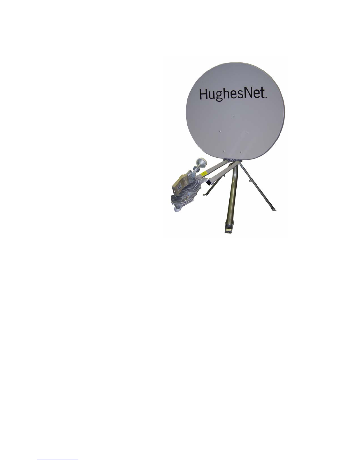
The Hughes model AN8-098R antenna is designed for Ka-band
applications. Figure 1 shows the AN8-098R assembled, with a
radio assembly.
verview of the AN8-098R antenna, a
page 1
page 2
n page 4
Chapter 1 • Overview
1037752-0001 Revision A
1
Page 16
Antenna installation
summary
Figure 1: The Hughes AN8-098R .98m Ka-band satellite antenna
This section lists the basic steps and related tasks used to
assemble and install the antenna. These procedures are listed in
the order in which they are to be performed. For more detailed
information on each task, refer to the chapters and documents
listed.
1. Explain the installation p
2. Conduct a site survey with the customer to ident
location for the antenna. See the HughesNet Antenna Site
Preparation and Mount Installation Guide (1035678-0001)
for details.
rocess to the customer.
ify a suitable
Chapter 1 • Overview
2
1037752-0001 Revision A
Page 17

3. Install and apply power to the satellite modem, following the
instructions in the installation guide for the specific satellite
modem you are installing.
Note: You must install the satellite modem before installing
the antenna to determine the proper pointing values (azimuth,
elevation, and tilt).
4. Connect your laptop computer
to the satellite modem and
enter the installation parameters from the installation
reference sheet.
5. Determine the most suitable method for mounting the
antenna and
install the antenna mast. See the Antenna Site
Preparation and Mount Installation Guide for details.
Note: It is critical that the antenna mast is plumb. The
antenna cannot be adjusted to correct for a mast that is not
plumb.
6. Attach the antenna reflector bracket and tilt plate to the Az/El
t. See Chapter 3 – Installing the antenna and
moun
radio
assembly.
7. Install the feed support arms and tailpiece. See
Chapter 3 – Installing the
8. Attach the antenna reflector. See Chapter 3 – Inst
antenna and radio assembly.
alling the
antenna and radio assembly.
9. Install the radio assembly, adjusting circular polarization if
necessary
. See Chapter 3 – Installing t
he antenna and radio
assembly.
10. Install the feed horn. See Chapter 3 – In
stalling the antenna
and radio assembly.
11. Attach the Az/El mount and ante
mast pipe. See Chapter 3 – Installing the antenna and
nna assembly to the antenna
radio
assembly.
12. Install the IFL transmit and rece
ive cables between the
satellite modem and the antenna. See Chapter 4 – Cabling
and connections.
13. Ground the antenna assembly. See Tasks related to antenna
installation on
page 4.
14. Determine the proper azimuth, elevation, and tilt. See
Chapter 3 – Installing the
antenna and radio assembly.
15. Point the antenna in accordance with the instructions in the
Ka-Band
16. Commission the satellite modem. F
Antenna Pointing Guide (1037663-0001).
or instructions, see the
installation guide for the specific satellite modem you are
installing.
Chapter 1 • Overview
1037752-0001 Revision A
3
Page 18

T asks related to antenna
installation
This section explains where to find information on tasks related to
antenna installation.
Selecting the
installation site
Installing the
antenna mount
The first and most important consideration when choosing a
prospective antenna site is whether the area can provide an
acceptable line of sight (LOS) to the satellite. A site with a clear,
unobstructed view of the southern sky is necessary. Also,
consider obstructions that may occur in the future, such as the
growth of trees. Select your antenna site before performing the
installation, so that the antenna will be able to receive the
strongest signal available.
Before selecting an installation site, check the
reference sheet to see if a customer-specific installation site has
been pre-determined and specified. Also, refer to the HughesNet
Antenna Site Preparation and Mount Installation Guide
(1035678-0001), which discusses the factors that you should
consider when selecting an antenna installation site.
As with any type of construction, a
required before installing the antenna. It is the property owner's
responsibility to obtain all permits. Install the antenna in
accordance with local building codes.
Before installing the antenna, you must first install a suitable
antenna mount. If the system requires a pole mount installation,
be sure to obtain information about the underground utilities in
the proposed location. Hav e the appropriate utility compan y mark
the location of any underground telephone wires, storm drains,
etc. Also, because soils vary widely in composition and load
capacity, it may be neces sary to consult a local professional
engineer to determine the appropriate foundation design.
local building permit may be
installation
Chapter 1 • Overview
4
1037752-0001 Revision A
For pole mounts that require a concrete base, you must allow at
24 hr for the concrete to cure before installing the antenna.
least
Be sure to plan and schedule the installation accordingly.
For complete information regarding antenna mount instal
including various mounting methods, refer to:
• The
customer-specific installation reference sheet
e HughesNet Antenna Site Preparation and Mount
• Th
Installation Guide (1035678-0001).
Refer to the installation reference
guidelines concerning the mount installation. Use only the
installation method described in the reference sheet.
sheet for any customer-specific
lation,
Page 19

If the installation reference sheet does not specify a method, use
only the mount installation methods documented in the
HughesNet Antenna Site Preparation and Mount Installation
Guide. Most installations in a commercial, industrial, or
institutional environment use a non-penetrating roof mount.
Installing the
satellite modem
Grounding
Approved cables
See the installation guide for the specific satellite modem you are
installing.
The entire antenna assembly must be grounded. For grounding
information, refer to your training, best grounding practices, the
Hughes Field Service Bulletin (FSB) HNS Broadband
Requirements for RG-6 and RG-11 IFL Cable Connectors,
Ground Blocks and Ground Block Location (FSB 050518_01),
and applicable parts of the National Electrical Code (NEC).
For a list of approved cables for the IFL between the antenna and
the satellite modem, see the Hughes FSB, IFL Cable, Appro ved
List (with lengths) for SPACEWAY Domestic Installations
(FSB 080111_01). The FSB lists the maximum cable length for
approved cable type for all relevant radio types.
each
Because it is impossible to predict
each installation site, you must use your own judgement and best
practices to determine how to route and connect the IFL transmit
and receive cables.
the requirements specific to
Chapter 1 • Overview
1037752-0001 Revision A
5
Page 20

Chapter 1 • Overview
6
1037752-0001 Revision A
Page 21

Antenna kit
components
Chapter 2
Antenna parts and required tools
This chapter describes the components and parts provided with
the AN8-098R Ka-band antenna kit. It contains the following
sections:
• Antenna kit components on page 7
• Small hardware parts list on
• Tools on
page 15
CAUTION
Metal components may contain sharp edges. Use care when
un-packing and handling antenna parts.
page 14
This section identifies and describes the main components of the
.98m Ka-band antenna kit. The antenna kit is shipped in three
containers. Figure 2 identifies the contents of each container.
Note: To avoid potential damage, leave all components in their
protective packages until required.
Chapter 2 • Antenna parts and required tools
1037752-0001 Revision A
7
Page 22

Figure 2: Antenna kit components
Note: The radio assembly is shipped separately and may not
arrive at the same time as the other two cartons.
The main components of the antenna kit are:
• Az/El mount assembly
• Refle
• T
• Feed support arms and tailpie
ctor bracket
ilt plate
ce
• Feed horn
• Ele
vation handle
• Antenna reflector
• Radio assembly
Related components (not shown):
• T
ri-mast or other antenna mount
Chapter 2 • Antenna parts and required tools
8
1037752-0001 Revision A
The following sections describe e
kit.
ach component of the antenna
Page 23

Az/El mount assembly
The Az/El mount assembly, shown in Figure 3, consists of the
Az/El canister, the elevation scale, an
d the fine azimuth and fine
elevation tools. The Az/El canister suppor ts the antenn a. The fine
azimuth and elevation tools are used to finely adjust the azimuth
and elevation of the reflector during antenna pointing. The
elevation scale is used to measure the antenna’s elevation during
the pointing phase.
Figure 3: Az/El mount assembly
Chapter 2 • Antenna parts and required tools
1037752-0001 Revision A
9
Page 24

Reflector bracket
and tilt plate
The reflector bracket supports the antenna reflector and allows
the reflector to rotate so that it can be adjusted for proper tilt. The
reflector bracket plate attaches to the Az/El mount assembly.
Figure 4 shows the reflector bracket and tilt plate.
Antenna reflector
Figure 4: Reflector bracket and tilt plate
The antenna reflector shown in Figure 5 focuses the transmitted
and received RF signals. It attaches to the reflec
Figure 5: Antenna reflector
tor bracket.
10
Chapter 2 • Antenna parts and required tools
1037752-0001 Revision A
Page 25

CAUTION
To avoid damage to the antenna reflector, handle it with
care. After assembly, do not use the reflector to rotate the
antenna.
Feed support arms
and tailpiece
Figure 6 shows the two feed support arms and the tailpiece. The
feed support arms attach to the ante
nna assembly at the reflector
bracket. The tailpiece is mounted to the ends of the feed support
arms and supports the radio assembly and feed horn.
Figure 6: Feed support arms and tailpiece
Chapter 2 • Antenna parts and required tools
1037752-0001 Revision A
11
Page 26

Radio assembly
The radio assembly shown in Figure 7 consists of the radio
transmitter, low noise block converter (LNB), transmit/receive
isolatio
n assembly (TRIA), and polarizing waveguide.
Figure 7: Radio assembly
Feed horn and collar
The feed horn, shown in Figure 8, attaches to the polarizer on the
radio assembly by way of the two-piece collar. The feed horn
gathers the reflected
signal from the reflector and focuses it
toward the LNB.
Figure 8: Feed horn and co llar
12
Chapter 2 • Antenna parts and required tools
1037752-0001 Revision A
Page 27

Elevation handle
Related Components
The elevation handle, shown in Figure 9, is used to adjust the
elevation of the antenna after assembly and installation.
Figure 9: Elevation handle
Wall
Tri-mast (or other
antenna mount)
T0144002
Figure 10: Tri-mast in various configurations
Although the tri-mast is not part of the antenna kit, it is described
here because it is the most commonly used mounting option for
the AN8-098R Ka-band antenna. As shown in Figure 10, the
tri-mast can be positioned in a number of conf
igurations to adapt
it for mounting onto surfaces of v arious an gles. Fo r other suitable
antenna mounting options, see the HughesNet Antenna Site
Preparation and Mount Installation Guide (1035678-0001).
Mast
Struts (2)
Flat roof
Pitched roof
Chapter 2 • Antenna parts and required tools
1037752-0001 Revision A
13
Page 28

Small hardware
parts list
Table 1 lists the small hardware parts included in the antenna kit.
Table 1: Small hardware par t s
Part Quantity
5/16-inch x 1-inch carriage bolts 5 Reflector bracket and tilt plate
5/16-inch flat washers 5
5/16-inch lock washers 5
5/16-inch hex nuts 5
5/16-inch x ¾-inch hex head
pping bolts
self-ta
5/16-inch flat washers 4
5/16-inch x 1¾-inch hex head
pping bolts
self-ta
5/16-inch flat washers 4
5/16-inch lock washers 4
5/16-inch hex nuts 4
5/16-inch x ¾-inch carriage bolts 5 Reflector to Az/El mount
5/16-inch serrated flange nuts 5
5/16-inch x ½-inch hex head bolts 2 Radio assembly (transmitter) to
5/16-inch flat washers 2
5/16-inch lock washers 2
O-ring 1 Feed horn to radio assembly Figure 22 on page 29
#6-32 (3mm) hexagonal socket
d (Allen) screws
hea
#6-32 (3mm) flat washers 2
4 Feed support arms to reflector
4 Tailpiece to feed support arms Figure 14 on page 22
2
Listed parts are
used to attach . .
and to Az/El mount assembly
bracket
sembly
as
e
tailpiec
.
Illustration showing
where parts are used
Figure 11 on page 19
Figure 13 on page 21
Figure 16 on page 23
Figure 18 on page 25
14
1037752-0001 Revision A
Chapter 2 • Antenna parts and required tools
Page 29

Tools
Table 2 lists the tools required to assemble and install the
antenna.
Table 2: Tools and additional materials required to assemble and
install the antenna
Tool or material Details
Socket wrench, ½-inch For 5/16-inch bolts.
2 open-end wrenches,
inch
½Torque wrench With 5/16-inch sockets capable of torquing
Long-shaft hexagonal
llen wrench, 7/64-inch
A
Torque wrench for
xagonal socket
he
Bubble level Used to make sure that the mast is plumb.
Compass Used to determine antenna azimuth.
Pencil Carpenter’s pencil.
Weather grade silicon
alant
se
Weatherproofing tape Used to keep moisture away from cable
Approved RG6 cable Used for IFL between satellite modem and
UV-rated cable ties Used to secure slack in cables to antenna
For 5/16-inch bolts. Some nuts and bolts
require a second wrench to prevent turning.
8 ft-lb.
to
For Allen screws with a 7/64-inch
hexagonal socket. Driver shaft should be at
least 5 inches long.
Must fit a 7/64-inch hexagonal socket and
be capable of torquing to 15 in-lb.
Used to keep moisture away from cable
connections.
ctions.
conne
a.
antenn
ast.
m
Chapter 2 • Antenna parts and required tools
1037752-0001 Revision A
15
Page 30

16
Chapter 2 • Antenna parts and required tools
1037752-0001 Revision A
Page 31

Chapter 3
Installing the antenna and
radio assembly
This chapter explains how to assemble and install the antenna,
radio assembly, and associated hardware. Topics in this chapter
include:
Determining the
pointing values
• Determining the pointing values on
• General instructions for assemb
• Installing the antenna reflector bracket and tilt plate on
page 19
• Installing the feed support arms and tailpiece on page 20
• Installing the antenna reflector on
• Installing the radio assembly on
• Installing the feed horn on
• Installing the antenna assembly onto
page 30
page 28
page 17
ling the antenna on page 18
page 22
page 24
the mast pipe on
CAUTION
Before you in stall the an tenna, read al l safety i nf ormation in
Important safety information on page iii.
Before installing the antenna, you must install and power up the
satellite modem. Refer to the appropriate satellite modem
installation guide for instructions.
Once the satellite modem is operational, connect it
using an Ethernet cable, then use your global positioning system
(GPS) receiver to calculate the exact latitude and longitude of the
antenna site. Follow the instructions in the HughesNet Ka-Band
Antenna Pointing Guide (1037663-0001) to enter the latitude
and longitude information to determine the initial antenna
azimuth, elevation, and tilt values. Record these values and keep
them handy for reference as you install and point the antenna.
Chapter 3 • Installing the antenna and radio assembly
1037752-0001 Revision A
to your laptop
17
Page 32

General instructions for
assembling the antenna
Before you assemble the antenna, read these important
instructions:
• Mast – The ma
st must be installed before you can install the
antenna. For information on installing the antenna mast, see
the HughesNet Antenna Site Preparation and Mount
Installation Guide (1035678-0001).
Note: The outside diameter of the mast must be
2 3/8 inches.
• Sequence
of steps – When you assemble the antenna, be sure
to follow the instructions in this chapter in the order they are
presented.
WARNING
For rooftop installations, assemble the ant enna on the
ground and then carry the fully assembled antenna up to
the roof.
ightening hardware – Do not tighten any nuts or other
• T
hardware until instructed to do so. (See also the next item,
Torque.)
• T
orque – T o ensure successful installation of the antenna, it is
critical that you tighten all nuts and socket-head screws to the
maximum torque values shown in Table 3.
Table 3: Torque specifications
Fastener Maximum torque
½-inch-inch bolts 8 ft-lb.
1/4-inch bolts 5 ft-lb.
18
Chapter 3 • Installing the antenna and radio assembly
1037752-0001 Revision A
Page 33

Installing the antenna
reflector bracket
and tilt plate
Begin the antenna assembly by attaching the antenna reflector
bracket to the Az/El mount:
1. Hold the reflector bracket in position o
that the tilt scale on the outside of the reflector bracket faces
the mount, as shown in Figure 11.
ver the Az/El mount so
Figure 11: Attaching the reflector bracket
2. While holding the reflector brack
plate over the opening in the reflector bracket so that the
letter A on the tilt plate lines up with the letter A on the arm
of the Az/El mount as shown in Figure 12 on page 20.
Because the hole pattern in the t
be sure that the two “A” indicators are aligned.
3. Insert five carriage bolts (½-inch × 1-inch) int
the tilt plate and through the corresponding holes in the Az/El
mount. You are going to bolt the tilt plate to the Az/El mount,
with the reflector bracket between them.
Chapter 3 • Installing the antenna and radio assembly
et in position, lay the tilt
ilt plate is not symmetrical,
o the holes in
1037752-0001 Revision A
19
Page 34

Figure 12: Aligning the Az/El mount
4. Secure the assembly by placing a flat washer, lock washer,
and ½-inch nut on each carriage bolt, as shown in
Figure 11
on page 19. Tighten each nut to 8 ft-lb usin g a torque wrench.
Once connected, the reflector brack
et should rotate freely
between the Az/El mount and the tilt plate.
Note: Tighten all 5/16-inch bolts to a maximum torque of
8 ft-lb.
When the reflector bracket and tilt plate are correctly
positioned on the Az/E
l mount assembly, you should be able
to clearly see the tilt scale numbers on the reflector bracket
from the rear, as shown in Figure 12.
Installing the
feed support arms
and tailpiece
20
Chapter 3 • Installing the antenna and radio assembly
1037752-0001 Revision A
Installation of the feed support arm is a two-step process. First,
you must connect the two feed support arms to the reflector
bracket; then you will connect the tailpiece (sometimes referred
to as the “beaver tail”) to the ends of the feed support arms.
1. Insert the feed support arms into the tw
o sockets at the
bottom of the reflector bracket, as shown in Figure 13.
Note: The two feed support arms are not identical. Be sure
to insert each arm into its appropriate socket as shown in the
figure, so that the holes in the feed support arms line up with
the corresponding holes in the reflector bracket.
Page 35

2. Fasten the feed support arms to the reflector bracket by
inserting a 5/16-inch × ¾-inch self-tapping bolt with flat
washer into each hole in the feed support arms, then tighten
until secure.
Figure 13: Attaching the feed support arms to the reflector bracket
3. Attach the tailpiece to the free ends of
the two feed support
arms as shown in Figure 14, using four 5/16-inch x 1¾-inch
self-tapping bolts, flat washers, lock washers, and nuts.
Chapter 3 • Installing the antenna and radio assembly
1037752-0001 Revision A
21
Page 36

Figure 14: Attaching the tailpiece
Installing the antenna
reflector
To attach the antenna reflector to the reflector bracket:
1. Insert a 5/16-inch x ¾-inch carriage bolt through the top hole
of
the reflector as shown in Figure 15, and place a 5/16-inch
flange nut on the bolt from the back. Do no
time.
t tighten at this
22
Chapter 3 • Installing the antenna and radio assembly
1037752-0001 Revision A
Figure 15: Insert first bolt into top hole
Page 37

2. Hold the reflector against the reflector bracket and lower it
onto the bracket, allowing the bolt to slide down into the
alignment fork at the top of the antenna bracket, as shown in
Figure 16.
Figure 16: Attaching the antenna reflector (rear view)
3. Insert the remaining four carriage bolts into
the holes in the
reflector and through the corresponding holes in the bracket
as shown in the figure.
4. Secure the bolts at the back of the reflector bracket, using
ur 5/16-inch flange nuts.
fo
Note: Ensure that the carriage bolts are firmly seated into
the square holes in the reflector before tightening the nuts.
Chapter 3 • Installing the antenna and radio assembly
1037752-0001 Revision A
23
Page 38

Installing the
radio assembly
To mount the radio assembly to the tailpiece:
1. Position the radio assembly abo
waveguide end of the radio is nearest to the reflector, as
shown in Figure 17.
ve the tailpiece so that the
Figure 17: Positioning the radio
2. Insert two 5/16-inch × ½-inch self-tappi
washers and lock washers, up through the tailpiece from
underneath, and into the threaded sockets on the bottom of
the radio transmitter, as shown in Figure 18.
3. Tighten the two bolts with a wrench
ng bolts, with flat
until secure.
24
Chapter 3 • Installing the antenna and radio assembly
1037752-0001 Revision A
Page 39

Figure 18: Attaching the radio assembly to the tailpiece
Adjusting transmit
circular polarization
It may be necessary to reposition the polarizer waveguide on the
radio assembly to set the proper polarization between the radio
transmitter and the antenna reflector. Before proceeding with the
installation, check the installation reference sheet to determine
whether the installation calls for left-hand circular polarization
(LHCP) or right-hand circular polarization (RHCP).
Once you determine which polarization setting is
required, check
the position of the polarizer waveguide to determine whether an
adjustment is necessary. From the rear of the radio, looking
toward the reflector, you can easily determine whether the
polarizer is currently set for LHCP or RHCP by the way it leans.
(See Figure 19.)
Note: There is no default factory setting for transmit
polarization. Radios can be shipped with either setting.
Chapter 3 • Installing the antenna and radio assembly
1037752-0001 Revision A
25
Page 40

Figure 19: Determining the polarization setting
To reposition the polarizer:
1. Remove the two-piece polarizer collar by loosening and
remo
ving the two Allen screws.
2. Separate the polarizer from the T
turn (clockwise for LHCP and counter-clockwise for RHCP),
until the appropriate notch lines up with the key on the end of
the TRIA. As shown in Figure 20, the LHCP notch is
adjacent to the L on the polarizer
adjacent to the R on the polarizer).
3. Reseat the waveguide wit h the TRIA and
collar.
RIA and rotate it one quarter
and the RHCP notch is
reassemble the
26
Chapter 3 • Installing the antenna and radio assembly
1037752-0001 Revision A
Page 41

Figure 20: Adjusting cir cula r pola rization (collar removed)
Chapter 3 • Installing the antenna and radio assembly
1037752-0001 Revision A
27
Page 42

Installing the feed horn
To attach the feed horn to the radio assembly:
1. Remove and discard the protecti ve seal from the polarizer on
the
radio assembly (shown in Figure 21).
28
Figure 21: Remove the protective seal from the polarizer
2. Remove the dust cap from the stem of the feed horn and
insert t
he O-ring into the groove inside the stem.
3. Position the feed horn against the waveguide as shown in
Figure 22
4. As shown in the figure, fit the two sections of the feed horn
collar around
the polarizer.
Chapter 3 • Installing the antenna and radio assembly
1037752-0001 Revision A
the ridge at the point where the feed horn meets
Page 43

Figure 22: Attaching the feed horn
5. Insert and tighten two Allen screws into the collar to secure
the feed horn in place.
6. At this point, fully tighten an
y hardware that is not tight—
however, leave nuts that are used for pointing adjustments
slightly loose or just snug.
Chapter 3 • Installing the antenna and radio assembly
1037752-0001 Revision A
29
Page 44

Installing the
antenna assembly
onto the mast pipe
Bubble must be centered
between marks.
Follow these steps to install the assembled antenna assembly onto
the mast pipe:
1. Before you install the Az/El mount
assembly onto the mast
pipe, use a bubble level to verify that the mast is plumb. The
mast must be plumb before you install the antenna assembly.
Check the mast at two locations, 90° apart, as shown in
Figure 23.
To make sure the mast is
plumb, check with the level
in two positions at right
angles to each other.
Mast
Level
Bubble
level
Top view
Mast
2nd level
position
Side view
Figure 23: Making sure the mast is plumb
2. Slide the Az/El mount assembly canister
pipe as shown in Figure 24.
Note: The outside diameter of the mast must be
2 3/8 inches.
T0144012
down onto the mast
30
Chapter 3 • Installing the antenna and radio assembly
1037752-0001 Revision A
Page 45

Figure 24: Installing the antenna assembly onto the mast
Note: For vertical mounts, fill all holes with weather-grade
silicon sealer before inserting bolts or screws. For horizontal
mounts, fill all holes with the appropriate asphalt-based,
synthetic-rubber, or acrylic co-polymer roof sealant.
This completes the assembly phase of the antenna installation
process. Depending on its orientation, the antenna should look
similar to the one shown in Figure 25.
Chapter 3 • Installing the antenna and radio assembly
1037752-0001 Revision A
31
Page 46

32
To proceed with the installation, you must route the IFL Tx and
Rx
cables between the antenna and the satellite modem. See
Chapter 4 – Cab
Chapter 3 • Installing the antenna and radio assembly
1037752-0001 Revision A
Figure 25: Assembled antenna
ling and connections.
Page 47

Chapter 4
Cabling and connections
This chapter illustrates where the antenna transmit, receive, and
ground connectors are located; shows how to route the transmit
and receive cables at the antenna; and explains ho w to connect the
transmit and receive cables to the radio assembly. You must
connect all of these cables before you can point the antenna
toward the HughesNet satellite.
Topics in this chapter include:
• Cabling requirements on page 33
• Routing the cables at the antenna on
• Connecting the transmit and receive cables on
• Ground connections on
page 38
page 34
page 36
Cabling requirements
For a list of approved cables for the intra-facility link (IFL)
between the antenna and the satellite modem, see the Hughes
FSB, IFL Cable, Approved List (with lengths) for SPACEWAY
Domestic Installations, (FSB 080202_01). The FSB lists the
maximum cable length for each approved cable type, for all
relevant radio types.
Because it is impossible to predict
each installation site, you must use your own judgement and best
practices to determine how to route and connect the IFL cables.
the requirements specific to
CAUTION
Coaxial cables and connectors can corrode if exposed to
moisture. Use only compression type connectors, and
weatherproof them with diel ectric grease and
weatherproofing tape.
Note: For connector requirements, see the Hughes FSB,
HN Broadband Requirements for RG-6 and RG-11 IFL
Cable Connectors, Ground Blocks and Ground Block
Location (FSB 050518_01).
Chapter 4 • Cabling and connections
1037752-0001 Revision A
33
Page 48

Routing the cables at
the antenna
Route the coaxial Tx and Rx cables at the antenna as follows:
1. Route the Tx cable (marked with blue electrical tape) over the
Az/El mount assembly
, down behind the reflector, and along
the feed support arms to the rear of the transmitter, in a
configuration similar to that shown in Figure 26.
Note: Do not exceed the minimum bending radius specified by
the cable manufacturer.
Figure 26: Transmit and receive cable configurations
34
Chapter 4 • Cabling and connections
1037752-0001 Revision A
2. Leave a 10-foot service loop secured to the mast, Az/El
mount ass
Note:
1. Do not lea
surface.
2. Do no
mount assembly.
embly, or reflector bracket.
ve the service loop on the roof or other mounting
t block access to the adjustment nuts on the Az/El
Page 49

3. Coil the extra cable, leave a drip loop, and secure the Tx
cable with cable ties.
4. Route the Rx cable (marked with red elec
trical tape) over the
Az/El mount assembly, down behind the reflector, and along
the feed support arms to the LNB, in a configuration similar
to that shown in Figure 26 above.
Note: Do not exceed the minimum bending radius specified by
the cable manufacturer.
5. Leave a 10-foot service loop secured to the mast, Az/El
mount ass
Note:
1. Do not lea
surface.
2. Do no
mount assembly.
embly, or reflector bracket.
ve the service loop on the roof or other mounting
t block access to the adjustment nuts on the Az/El
6. Coil the extra cable, leave a drip loop, and secure the Rx
able with cable ties.
c
Chapter 4 • Cabling and connections
1037752-0001 Revision A
35
Page 50

Connecting the transmit
and receive cables
This section explains how to connect the Tx and Rx cables to the
radio assembly at the antenna.
Note: You should secure all cable connections with
dielectric grease and weatherproofing tape as shown in
Figure 27. However, because the antenna pointing procedure
requires that you disconnect the cables, you should wait until
he pointing process is complete before weatherproofing the
t
connections.
Transmit cable
Figure 27: Weatherp r oo fin g th e cable connec to rs
Connect the Tx cable to the radio transmitter as follows:
1. Remove power from the satellite modem.
2. Connect the Tx cable (marked with blue electrical
tape) to the
transmitter connector marked IFL, shown in Figure 28.
CAUTION
Coaxial cables and connectors can corrode if exposed to
moisture. Use only compression type connectors, and
weatherproof them with diel ectric silicone grease and
weatherproofing tape.
3. Tighten the cable connector to 22
4. Apply dielectric silicone grease t
5. If necessary, secure the cable with cable ties.
in-lb with a torque wrench.
o the connection.
36
Chapter 4 • Cabling and connections
1037752-0001 Revision A
Page 51

Figure 28: Transmit connector
Receive cable
Connect the Rx cable to the LNB as follows:
1. Ensure that power has been remo
ved from the satellite
modem.
2. Connect the Rx cable (marked with red elect
rical tape) to the
receive connector on the LNB, shown in Figure 29.
CAUTION
Coaxial cables and connectors can corrode if exposed to
moisture. Use only compression type connectors, and
weatherproof them with diel ectric grease and
weatherproofing tape.
Figure 29: Receive connector
3. Fill the connector with dielectric silicone grease and tighten
cable connector to 22 in-lb with a torque wrench.
the
Chapter 4 • Cabling and connections
1037752-0001 Revision A
37
Page 52

4. If necessary, secure the cable with cable ties.
5. After both the Tx and Rx cables are connected to the radio
and the satellite modem, reapply power to the satellite
modem in accordance with the instructions in the satellite
modem installation guide.
Ground connections
Ground the antenna mast at the Az/El mount. Figure 30 shows the
location of the ground screw. For specific grounding procedures,
refer to
Note: Although the radio transmitter contains a ground screw, a
separate ground wire to the radio assembly is not required; the
radio assembly is grounded though the metallic shield of the
coaxial cable.
the sources listed in Grounding o
n page 5.
38
Chapter 4 • Cabling and connections
1037752-0001 Revision A
Figure 30: Ground screw location on the Az/El mount
This completes the installation. Y
ou must now point the antenna.
See the HughesNet System Ka-Band Antenna Pointing Guide
(1037663-0001) for details.
Page 53

Chapter 5
Adjusting the antenna
azimuth and elevation
This chapter describes the process by which to adjust the antenna
azimuth and elevation to the correct position. As the installer , you
will perform these procedures during the antenna pointing
process. This chapter discusses the mechanical adjustments used
to modify the position of the antenna only. It does not discuss the
pointing process itself. For information on pointing the
AN8-098R and all HughesNet Ka-Band antennas, see the
HughesNet Ka-Band Antenna Pointing Guide (1037663-00 01).
This chapter contains the follo
• Adjusting the elevation on
• Adjusting the azimuth o
n page 42
wing sections:
page 40
Chapter 5 • Adjusting the antenna azimuth and elevation
1037752-0001 Revision A
39
Page 54

Adjusting the elevation
1. T o be gin, unlock th e ele vation b y loosening the two 5/16-inch
elevation lockdown nuts on either side of the Az/El mount.
Figure 31 shows the location of the nuts (only one nut is
shown).
Figure 31: Elevation adjustment components
2. Insert the elevation handle into the
hole at the bottom of the
elevation adjustment tool as shown in Figure 32 and rotate it
90° to lock it in place.
40
Chapter 5 • Adjusting the antenna azimuth and ele va tio n
1037752-0001 Revision A
Page 55

Figure 32: Adjustin g th e elevation
3. Turn the handle to adjust the elevation. As shown in
Figure 33, the pointer on the lockdown
in the elevation scale. For example, the
nut indicates the value
antenna shown in the
figure is adjusted to 42°.
Figure 33: Elevation marker
4. Tighten the two lockdown nuts on
either side of the Az/El
mount using a ½-inch socket and torque wrench to secure the
elevation setting in place.
Chapter 5 • Adjusting the antenna azimuth and elevation
1037752-0001 Revision A
41
Page 56

Adjusting the azimuth
1. Be sure that the three 5/16-inch azimuth lockdown nuts at the
bottom of the Az/El canister (shown in Figure 34) are loose
enough that the canister rotates freely on the mast.
Figure 34: Loosen the Az/El canister
2. Manually point the
antenna reflector in the appropriate
direction as indicated on the installation reference sheet.
CAUTION
Do not attempt to adj ust the azi m uth man uall y b y pul ling on
the antenna reflector or feed support arms. Doing so could
cause permanent damage to the antenna.
3. Tighten the three lockdown nuts to secure
position.
4. Loosen the four 5/16-inch carriage bolts on the bottom of the
az
imuth base, shown in Figure 35.
the antenna in
42
Chapter 5 • Adjusting the antenna azimuth and ele va tio n
1037752-0001 Revision A
Page 57

Figure 35: Adjusting the azimuth
5. Turn the 5/16-inch fine azimuth adjustment bolt at the right
side of the azimuth base to achieve the desired azimuth angle.
Note: Azimuth measurements are calibrated relative to true
north, not magnetic north.
6. Verify the azimuth with a compass and lock down the four
5/16-inch carriage bolts on the
bottom of the azimuth base to
177 in-lb using a 1/2-inch socket torque wrench, tightening
opposing corners uniformly.
Chapter 5 • Adjusting the antenna azimuth and elevation
1037752-0001 Revision A
43
Page 58

44
Chapter 5 • Adjusting the antenna azimuth and ele va tio n
1037752-0001 Revision A
Page 59

Acronyms and abbreviations
A
Az – Azimuth
E
El – Elevation
F
FSB – Field service bulletin
ft – Foot/feet
ft-lb – Foot-pounds
G
GPS – Global positioning system
H
hr – Hour/hours
I
RHCP – Right-hand circular polarization
Rx – Receive
T
TRIA – Transmit/receive isolation assembly
Tx – Transmit
IFL – Intra-facility link
L
LHCP – Left-hand circular polarization
LNB – Low noise block converter
M
m – Meters
N
NEC – National Electrical Code
NOCC – Network Operations Control Center
R
RF – Radio frequency
• Acronyms and abbreviations
1037752-0001 Revision A
45
Page 60

46
• Acronyms and abbreviations
1037752-0001 Revision A
Page 61

Index
A
Antenna
kit components
mount installation 2, 4, 13
reflector 10
Az/el mount assembly
description
installing 19–20
mounting to mast 30–31
7
9
C
Cables
approved types
connecting to radio assembly 36
maximum length 5, 33
receive cable 37
routing at the antenna 34
service loops 34
transmit cable 36
Components 7
Connecting
cables to the radio assembly
receive cable 37
transmit cable 36
Connectors 33
5, 33
E
Elevation handle 13
F
Feed horn
description
installing 28–29
Feed support arms
description
installing 20
12
11
G
Grounding 5
ground screw location 38
36
H
Hardware parts list 14
I
IFL 5, 33
Installation site, determining 4
Installation, summary of steps 2
Installing
antenna mount
pole mount installation requirements 4
az/el mount 19–20
feed horn 28–29
feed support arms 20–22
radio assembly 24–27
reflector 22–23
reflector bracket 19–20
satellite modem 5
tailpiece 20–22
tilt plate 19–20
4–5, 13
L
Leveling the mast 30
M
Mast 18
P
Parts list 14
Pointing values 17
Polarization, adjusting 25
R
Radio assembly
description
installing 24–27
Receive cable
connecting to the LNB
routing 35
Reflector
description
12
37
10
• Index
1037752-0001 Revision A
47
Page 62

installing 22–23
Reflector bracket
description
installing 19–20
10
S
Satellite modem, installing 5
Site survey, conducting 2
Summary of installation steps 2
T
Tailpiece
description
installing 20–22
Tasks related to installation 2, 4
Tilt plate
description
installing 19–20
Tilt scale 19, 20
Tool list 15
Torque 18
Transmit cable
connecting
routing 34
Transmitter 12
connecting 36
Tri-mast 13
11
10
36
48
• Index
1037752-0001 Revision A
 Loading...