

Hughes AN8-074P Installation Manual

0.74 m Ka-Band Antenna
Installation Guide –
Model AN8-074P
1037749-0001
Revision F
3/26/2013
11717 Exploration Lane, Germantown, MD 20876
Phone (301) 428-5500 Fax (301) 428-1868/2830

Copyright © 2013 Hughes Network Systems, LLC
All rights reserved. This publication and its contents are proprietary to Hughes Network
Systems, LLC. No part of this publication may be reproduced in any form or by any means
without the written permission of Hughes Network Systems, LLC, 11717 Exploration Lane,
Germantown, Maryland 20876.
Hughes Network Systems, LLC has made every effort to ensure the correctness and
completeness of the material in this document. Hughes Network Systems, LLC shall not be liable
for errors contained herein. The information in this document is subject to change without
notice. Hughes Network Systems, LLC makes no warranty of any kind with regard to this
material, including, but not limited to, the implied warranties of merchantability and fitness for
a particular purpose.
Trademarks
HUGHES and Hughes Network Systems are trademarks of Hughes Network Systems, LLC. All
other trademarks are the property of their respective owners.

Contents
1037749-0001 Revision F
3
Contents
Contents ................................................................................................. 3
Understanding safety alert messages .................................................... 5
Messages concerning personal injury .................................................................... 5
Messages concerning property damage ................................................................ 5
Safety symbols ....................................................................................................... 6
Additional symbols ........................................................................................... 6
Antenna installation safety .................................................................................... 7
Chapter 1
Overview ............................................................................................... 11
Model AN8-074P antenna description ................................................................ 12
Antenna installation summary ............................................................................. 13
Tasks related to antenna installation .................................................................. 14
Selecting the installation site .......................................................................... 14
Installing the antenna mount ......................................................................... 14
Installing the IDU ............................................................................................ 15
Grounding ....................................................................................................... 15
Approved cables ............................................................................................. 15
Chapter 2
Antenna parts and recommended tools ............................................... 17
Antenna kit components ..................................................................................... 17
Az/El mount assembly .................................................................................... 18
Reflector bracket and tilt plate ....................................................................... 19
Antenna reflector ........................................................................................... 19
Feed support arm ........................................................................................... 20
Radio assembly ............................................................................................... 20
Feed horn ........................................................................................................ 21
Polarizer clamps .............................................................................................. 21
Small hardware parts list ..................................................................................... 22
Tools ..................................................................................................................... 23
Chapter 3
Installing the antenna and radio assembly .......................................... 25
Determining the pointing values ......................................................................... 25
General instructions for assembling the antenna ............................................... 26
Installing the reflector bracket and tilt plate ....................................................... 27
Installing the antenna reflector ........................................................................... 28
Installing the feed support arm ........................................................................... 30
Installing the radio assembly ............................................................................... 31
Changing transmit circular polarization (if needed) ....................................... 33
Installing the feed horn ........................................................................................ 36
Attaching the clamp........................................................................................ 37
Securing the feed horn ................................................................................... 39

4
Contents
1037749-0001 Revision F
Installing the antenna assembly onto the mast .................................................. 39
Chapter 4
Cabling and connections....................................................................... 41
Cabling requirements .......................................................................................... 41
Routing the cables at the antenna ....................................................................... 42
Routing the transmit cable ............................................................................. 43
Routing the receive cable ............................................................................... 43
Connecting the transmit and receive cables ....................................................... 44
Connecting the transmit cable ....................................................................... 44
Connecting the receive cable ......................................................................... 45
Ground connection .............................................................................................. 45
Pointing ................................................................................................................ 45
Chapter 5
Adjusting antenna azimuth and elevation ........................................... 47
Adjusting elevation .............................................................................................. 48
Adjusting azimuth ................................................................................................ 50
Checking the azimuth base starting position ................................................. 51
Coarse azimuth adjustment ............................................................................ 52
Fine azimuth adjustment ................................................................................ 52
Final steps ............................................................................................................ 53
Remove the pointing tool ............................................................................... 53
Weatherproof the cable connections ............................................................. 53
Check for safety labels and signs .................................................................... 54
Acronyms and abbreviations ................................................................ 55
Index .................................................................................................... 57
Understanding safety alert messages
1037749-0001 Revision F
5
DANGER indicates a potentially hazardous situation which, if not avoided, will result
in death or serious injury.
WARNING indicates a potentially hazardous situation which, if not avoided, could
result in death or serious injury.
CAUTION indicates a potentially hazardous situation which, if not avoided, could
result in minor or moderate injury.
NOTICE is used for advisory messages concerning possible property damage, product
damage or malfunction, data loss, or other unwanted results – but not personal
injury.
Understanding safety alert messages
Safety alert messages call attention to potential safety hazards and tell you how to
avoid them. These messages are identified by the signal words DANGER, WARNING,
CAUTION, or NOTICE, as illustrated below. To avoid possible property damage,
personal injury, or in some cases possible death, read and comply with all safety
alert messages.
Messages concerning personal injury
The signal words DANGER, WARNING, and CAUTION indicate hazards that could
result in personal injury or in some cases death, as explained below. Each of these
signal words indicates the severity of the potential hazard.
Messages concerning property damage
A NOTICE concerns property damage only.
6
Understanding safety alert messages
1037749-0001 Revision F
Indicates a safety message that concerns a potential electric
shock hazard.
Indicates a safety message that concerns a potentially
hazardous situation in which you could fall.
Indicates a safety message that concerns radio frequency
(RF) energy.
Safety symbols
Additional symbols
The generic safety alert symbol
calls attention to a potential personal injury hazard. It appears next to the DANGER,
WARNING, and CAUTION signal words as part of the signal word label. Other
symbols may appear next to DANGER, WARNING, or CAUTION to indicate a specific
type of hazard (for example, fire or electric shock). If other hazard symbols are used
in this document they are identified in this section.
This document uses the following hazard symbols:
Understanding safety alert messages
1037749-0001 Revision F
7
Only Hughes‐certified installers may install or service Hughes antennas and their
components. Installers must expressly acknowledge the Hughes requirements for
Hughes installations.
If you work on a roof, tower, or other high structure or use a ladder or scaffold to
access the work site, follow these precautions to prevent personal injury or death:
so that they can support all loads (equipment weight, ice, and wind).
used.
call the local power company to remove it. Do not try to remove it yourself.
underground utilities in the proposed location before digging.
Properly ground the antenna assembly in accordance with all local and national
electrical codes.
Antenna installation safety
Observe the following precautions when installing the satellite antenna. This
manual also includes other safety alerts where appropriate concerning specific
installation procedures.
8
Understanding safety alert messages
1037749-0001 Revision F
weather conditions are either present or approaching.
a slight wind can unexpectedly create sudden strong forces on the antenna
surface.
If the antenna or mount assembly begins to fall during the installation, do not
attempt to catch it. Move away and let it fall.
Antennas that have been improperly installed or attached to an unstable structure
are susceptible to wind damage, which can be very serious or even life threatening.
The product owner and installer assume full responsibility that the installation is
structurally sound to support all loads (weight, wind, and ice) and is properly sealed
against leaks.

Understanding safety alert messages
1037749-0001 Revision F
9
Observe these precautions to avoid exposure to RF radiation, a potential safety
hazard:
in a manner that prevents human exposure to potentially harmful levels of
radiation.
with a greater than 30° elevation angle must be installed such that the lower lip
of the antenna reflector is at least 5 ft above any surface upon which a person
might be expected to stand, and 3 ft 3 inches from any opening (such as a door
or window) in a building or adjacent structure.
elevation must be installed such that the lower lip of the antenna reflector is at
least 5 ft 9 inches above any surface upon which a person might be expected to
stand, and 3 ft 3 inches from any opening (such as a door or window) in a
building or adjacent structure.
expected to support a person is within 6 ft 7 inches of the edges of a cylindrical
space projecting outward from the antenna reflector toward the satellite.
mounted in a controlled area inaccessible to the general public, such as a fenced
enclosure or a roof.
large enough to protect the general public from exposure to potentially harmful
levels of radiation.
environment must be limited by a door or a permanently fastened ladder that is
locked to deny access to the general public.
feet.
Failure to observe these cautions could result in injury to eyes or other personal
injury.

10
Understanding safety alert messages
1037749-0001 Revision F
Observe these precautions to avoid exposure to RF radiation, a potential safety
hazard:
approved Radiation Hazard Caution label on the feed support arm.
environment must carry a Radiation Hazard Caution sign on the access door,
gate, or permanently mounted access ladder within plain sight of anyone
approaching the antenna from the front or sides of the reflector.
Failure to observe these cautions could result in injury to eyes or other personal
injury.
Note: Some installations may require additional precautions. See the HughesNet
System Antenna Site Preparation and Mount Installation Guide (1035678‐
0001) for more information.

Chapter 1 • Overview
1037749-0001 Revision F
11
Chapter 1
Overview
This installation guide explains how to assemble and install the Hughes AN8-074P
0.74 m Ka-band antenna. It is written for qualified installers who are familiar with
satellite antenna installation practices, and are capable of properly applying the
information presented.
This chapter includes the following sections:
Model AN8-074P antenna description on page 12
Antenna installation summary on page 13
Tasks related to antenna installation on page 14
12
Chapter 1 • Overview
1037749-0001 Revision F
Model AN8-074P antenna description
The Hughes model AN8-074P antenna is designed for Ka-band applications. Each
HughesNet antenna station consists of an antenna assembly and an indoor unit
(IDU), which can be either a satellite modem or a satellite router. The IDU
communicates with both the HughesNet satellite and the Network Operations
Control Center (NOCC) via the antenna and radio assembly.
The antenna is connected to the IDU by an intra-facility link (IFL) consisting of two
cables: a transmit cable and a receive cable.
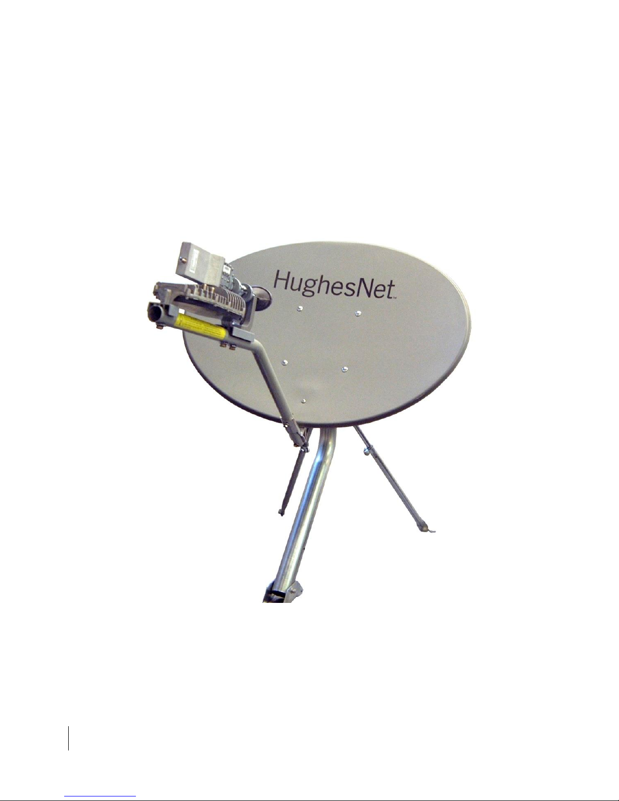
Figure 1 shows the AN8-074P antenna, with radio assembly, assembled and
installed on a trimast mount.
Figure 1: Hughes model AN8-074P 0.74 m satellite antenna

Chapter 1 • Overview
1037749-0001 Revision F
13
Task
For details, see…
1
Explain the installation process to the customer.
2
Conduct a site survey with the customer to identify
a suitable location for the antenna.
Selecting the installation site on page 14 and Antenna
Site Preparation and Mount Installation Guide
(1035678-0001)
3
Power on and install the IDU.
Note: You must install the IDU before installing the
antenna so you can determine the antenna
pointing values (azimuth, elevation and tilt).
IDU installation guide
4
Determine the most suitable method for mounting
the antenna; then install the antenna mast.
Note: The antenna mast must be plumb. The
antenna cannot be adjusted to correct for a mast
that is not plumb.
Installing the antenna mount on page 14 and Antenna
Site Preparation and Mount Installation Guide
(1035678-0001)
5
Assemble the antenna (Az/El mount, feed support
arms, reflector, and other parts).
Chapter 3 – Installing the antenna and radio assembly
on page 25
6
Install the radio assembly and feed horn.
Installing the radio assembly on page 31 Installing the
feed horn on page 36
7
Install the antenna assembly on the mast.
Installing the antenna assembly onto the mast on page
39
8
Install the IFL transmit and receive cables between
the IDU and the antenna.
Chapter 4 – Cabling and connections on page 43
9
Ground the antenna assembly.
Grounding on page 45
10
Point the antenna.
Pointing procedure: Ka-Band Antenna Pointing Guide
(1037663-0001)
Mechanical adjustments for pointing:
Chapter 5 – Adjusting antenna azimuth and elevation
Antenna installation summary
This section lists the basic steps and related tasks for installing the satellite antenna.
Follow all steps in the order in which they are presented here and elsewhere in this
guide. For detailed information on each task, refer to the listed section or chapter in
this guide or other listed documents.
Table 1: Satellite antenna installation summary
When the antenna is properly pointed you can commission the IDU as instructed in
the IDU installation guide.

14
Chapter 1 • Overview
1037749-0001 Revision F
Tasks related to antenna installation
This section discusses tasks related to antenna installation and explains where to
find additional information.
Selecting the installation site
Before selecting an installation site, check the installation reference sheet to see if a
customer-specific installation site has been pre-determined and specified. Also,
refer to the HughesNet Antenna Site Preparation and Mount Installation Guide
(1035678-0001), which discusses the factors that you should consider when
selecting an antenna installation site.
The first and most important consideration when choosing a prospective antenna
site is whether the area can provide an acceptable line of sight (LOS) to the satellite.
A site with a clear, unobstructed view of the southern sky is necessary. Also,
consider obstructions that may occur in the future, such as the growth of trees.
Select your antenna site before performing the installation, so that the antenna will
be able to receive the strongest signal available.
As with any type of construction, a local building permit may be required before
installing the antenna. It is the property owner's responsibility to obtain necessary
permits and comply with local building codes.
Installing the antenna mount
Before installing the antenna itself, you must first install a suitable antenna mount.
If the system requires a pole mount installation, be sure to obtain information
about the underground utilities in the proposed location. Have the appropriate
utility company mark the location of any underground telephone wires, storm
drains, etc. Also, because soils vary widely in composition and load capacity, it may
be necessary to consult a local professional engineer to determine the appropriate
foundation design.
For pole mounts that require a concrete base, you must allow at least 24 hr for the
concrete to cure before installing the antenna. Be sure to plan and schedule the
installation accordingly.
For complete information regarding antenna mount installation, including various
mounting methods, refer to:
The customer-specific installation reference sheet
The HughesNet Antenna Site Preparation and Mount Installation Guide
(1035678-0001)
Refer to the installation reference sheet for any customer-specific guidelines
concerning the mount installation. Use only the installation method described in the
reference sheet.
If the installation reference sheet does not specify a method, use only the mount
installation methods documented in the HughesNet Antenna Site Preparation and
Mount Installation Guide (1035678-0001). Most installations in a commercial,
industrial, or institutional environment use a non-penetrating roof mount.

Chapter 1 • Overview
1037749-0001 Revision F
15
Installing the IDU
See the installation guide for the specific IDU you are installing.
Grounding
The antenna assembly must be grounded. For grounding information, refer to your
training, best grounding practices, the Hughes Field Service Bulletin (FSB) HNS
Broadband Requirements for RG-6 and RG-11 IFL Cable Connectors, Ground Blocks
and Ground Block Location (FSB 050518_01), and applicable parts of the National
Electrical Code (NEC).
Approved cables
For a list of approved coaxial cable types for the IFL between the antenna and the
IDU, see the Hughes FSB, IFL Cable, Approved List (with lengths) for SPACEWAY
Domestic Installations (FSB 080202_01). The FSB lists the maximum cable length for
each approved cable type for all relevant radio types.
Because it is impossible to predict the requirements specific to each installation site,
you must use your own judgment and best practices to determine how to route and
connect the IFL transmit and receive cables.

Antenna parts and recommended tools
1037749-0001 Revision F
17
Metal components may contain sharp edges. Use care when unpacking and
handling antenna parts.
Chapter 2
Antenna parts and recommended tools
This chapter identifies the main components and parts provided with the AN8-074P
Ka-band antenna kit. It includes the following sections:
Antenna kit components
Small hardware parts list on page 22
Tools on page 23
Antenna kit components
When you receive the equipment, unpack and inspect the antenna components and
hardware to make sure all parts have been received in good condition.
If any parts appear to have been damaged in transit, immediately contact the
freight carrier. If any parts appear to be missing or damaged, but not as a result of
handling in transit, contact your dealer or distributor.
The antenna kit is shipped in two boxes; the radio assembly is shipped separately in
a third box.
Note: To avoid potential damage, leave all components in their protective
packages until required.
18
Antenna parts and recommended tools
1037749-0001 Revision F
The main components of the antenna kit are:
Az/El mount assembly
Reflector bracket and tilt plate
Antenna reflector
Feed support arm
Radio assembly (shipped separately)
Feed horn
The following sections describe and illustrate each component of the antenna kit.
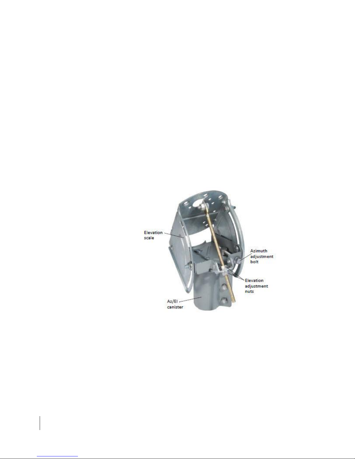
Az/El mount assembly
The Az/El mount assembly, shown in Figure 2, includes components that allow you
to adjust the antenna elevation and azimuth—the Az/El canister, the elevation
scale, and the azimuth and elevation adjustment tools.
The Az/El canister supports the antenna and secures it to the mast. The elevation
scale is used to measure the angle of antenna elevation. The azimuth and elevation
adjustment tools are used to finely adjust the azimuth and elevation of the reflector
during antenna pointing. See the HughesNet Ka-Band Antenna Pointing Guide
(1037663-0001) for detailed instructions.
Figure 2: Az/El mount assembly
 Loading...