

Hughes AN6-074S Installation Manual

Hughes
Installation Manual for
.74 m Ku-band Upgradeable
Antenna Model AN6-074S
1036469-0001
Revision D
March 31, 2006

Copyright © 2005, 2006 Hughes Network Systems, LLC
All rights reserved. This publication and its contents are proprietary to Hughes Network Systems,
LLC. No part of this publication may be reproduced in any form or by any means without the written
permission of Hughes Network Systems, LLC, 11717 Exploration Lane, Germantown, Maryland
20876.
Hughes Network Systems, LLC has made every effort to ensure the correctness and completeness
of the material in this document. Hughes Network Systems, LLC shall not be liable for errors
contained herein. The information in this document is subject to change without notice. Hughes
Network Systems, LLC makes no warranty of any kind with regard to this material, including, but not
limited to, the implied warranties of merchantability and fitness for a particular purpose.
Trademarks
Hughes, Hughes Network Systems, and HughesNet are trademarks of Hughes Network Systems,
LLC. All other trademarks are the property of their respective owners.
Important safety information
For your safety and protection, read this entire installation manual
before you attempt to install the satellite antenna. In particular,
read this safety section carefully. Keep this safety information
where you can refer to it if necessary.
Types of warnings used
in this manual
This section introduces the various types of warnings used in this
manual to alert you to possible safety hazards.
DANGER
Indicates an imminently hazardous situation, which, if not
avoided, will result in death or serious injury.
WARNING
Indicates a potentially hazardous situation, which, if not
avoided, could result in death or serious injury.
CAUTION
Indicates a potentially hazardous situation, which, if not
avoided, may result in minor or moderate injury.
CAUTION
Indicates a situation or practice that might result in property
damage.
• Important safety information
1036469-0001 Revision D
iii
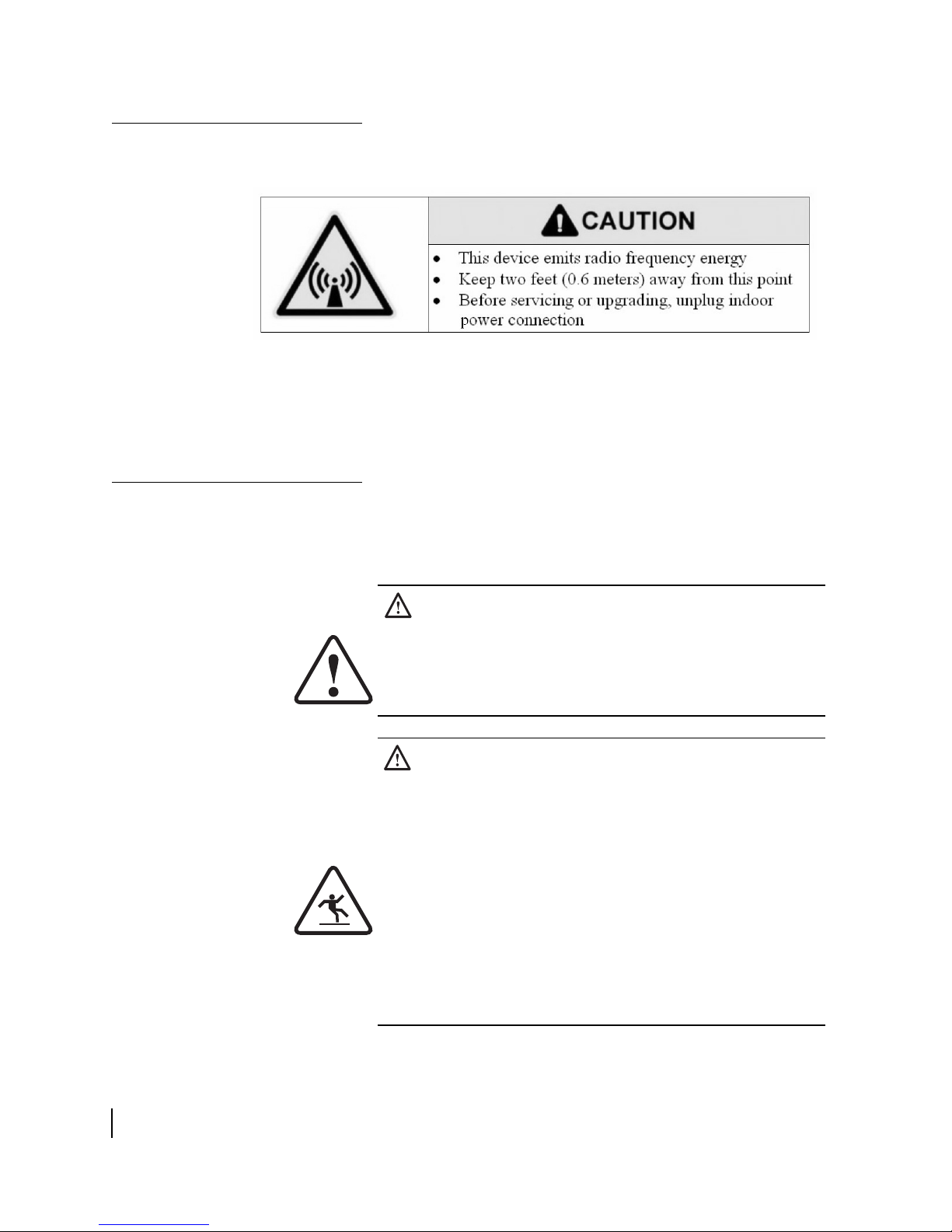
Product warning labels
The following safety alert label is affixed to each side of the
satellite antenna feed arm:
This label advises that the antenna emits radio frequency (RF)
energy. Because of this potential safety hazard, observe all
cautions in the following section (
Antenna installation safety)
concerning RF radiation.
Antenna installation
safety
Observe the following precautions when installing the satellite
antenna. This manual also includes additional safety alerts where
appropriate concerning specific installation
procedures.
WARNING
Only Hughes-certified installers can install or service
Hughes earth stations and components. All
Hughes-certified installers must expressly acknowledge the
Hughes requirements for installations.
DANGER
If you work on a roof, tower, or other high structure or use a
ladder or scaffold to access the work site, follow these
precautions to prevent personal injury or death:
• Walk only on sound roof structures.
• Make sure the antenna assembly and installation
surface are structurally sound so they can support all
loads (equipment weight, ice, and wind).
• Use appropriate safety equipment (for example, a
lifeline), depending on the work location.
• Follow all safety precautions from the manufacturers of
all safety equipment and other equipment used.
• Perform as many procedures as possible on the ground.
• Important safety information
iv
1036469-0001 Revision D
DANGER
• To avoid electric shock, stay at least 20 ft from power
lines.
• If any part of the antenna or mount assembly comes in
contact with a power line, call your local power
company to remove it.
Failure to heed these warnings could result in serious injury
or death.
Do not try to remove it yourself.
WARNING
• Do not work in high wind or rain or if a storm, lightning,
or other adverse weather conditions are present or
approaching.
• Do not attempt to assemble, move, or mount the
antenna on a windy day. Even a slight wind can
unexpectedly create strong, unexpected forces on the
antenna surface.
• Important safety information
1036469-0001 Revision D
v
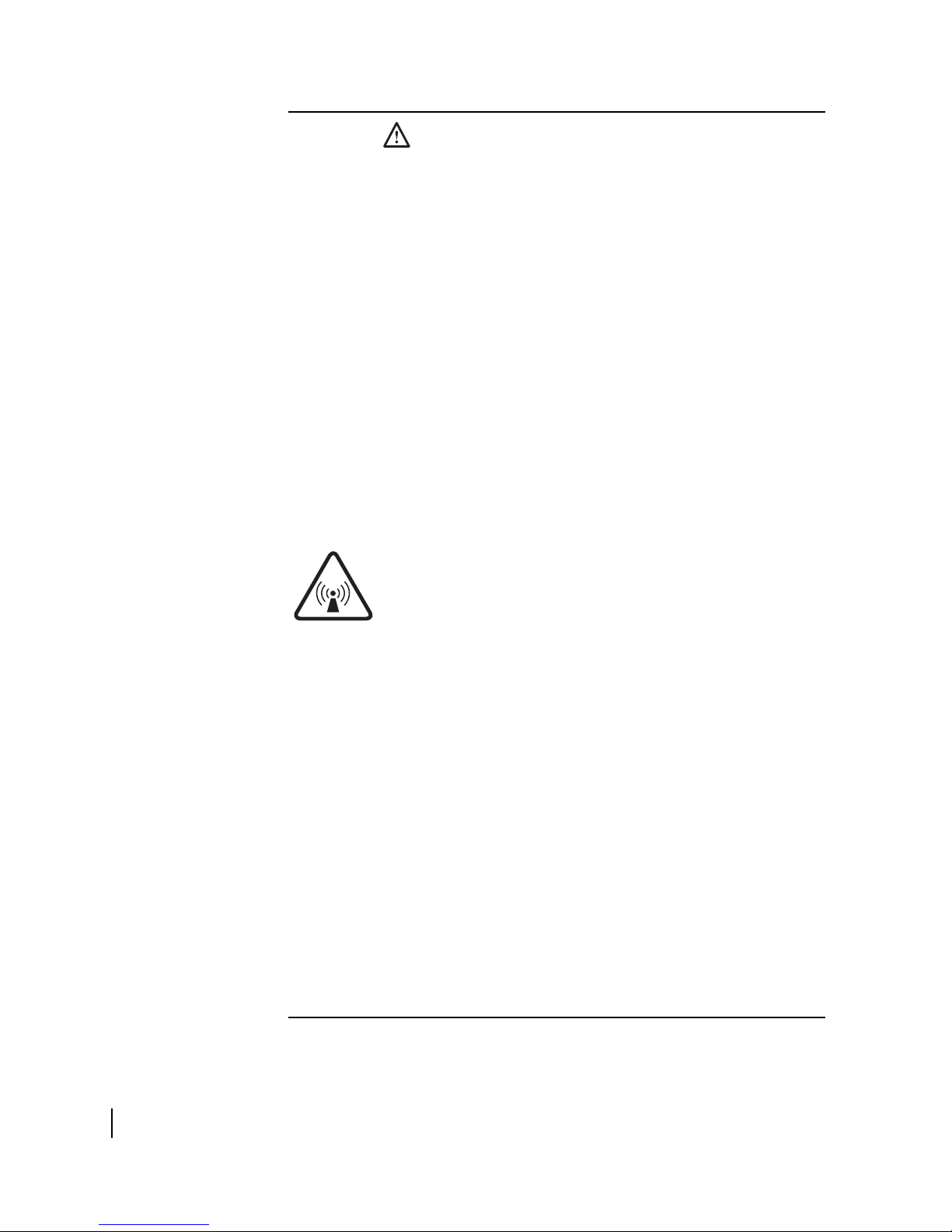
CAUTION
Observe these precautions to avoid exposure to RF
radiation, a potential safety hazard:
• The antenna must be installed in a location or manner
not readily accessible to children and in a manner that
prevents human exposure to potentially harmful levels
of radiation.
• Antennas mounted in Puerto Rico, the continental
United States, or at any site with greater than a 30°
elevation angle must be installed such that the lower lip
of the antenna reflector is at least 5 ft above any surface
upon which a person might be expected to stand, and 3
ft 3 in. from any opening (such as a door or window) in a
building or adjacent structure.
• Antennas mounted in Canada, Alaska, Hawaii, or any
site with less than a 30° elevation must be installed such
that the lower lip of the antenna reflector is at least
5
ft 9 in. above any surface upon which a person might
be expected to stand, and 3 ft 3 in. from any opening
(such as a door or window) in a building or adjacent
structure.
• The antenna must be mounted such that no object
which could reasonably be expected to support a
person is within 6 ft 7 in. of the edges of a cylindrical
space projecting outward from the antenna reflector
toward the satellite.
• If the above distance requirements cannot be met, the
antenna must be mounted in a controlled area
inaccessible to the general public, such as a fenced
enclosure or a roof.
• The antenna must be mounted such that there is no
object outside the controlled area which could
reasonably be expected to support a person within
6
ft 7 in. of the edges of a cylindrical space projecting
outward from the antenna reflector toward the satellite.
• A fenced installation must have a locked entry, and the
fenced area must be large enough to protect the general
public from exposure to potentially harmful levels of
radiation.
• Access to a roof installation in a commercial, industrial,
or institutional environment must be limited by a door or
a permanently fastened ladder that is locked to deny
access to the general public.
• Important safety information
vi
1036469-0001 Revision D
Failure to observe these cautions could result in injury to
eyes or other personal injury.
CAUTION
• All installations of any type or size must carry an
industry standard and government approved
Hazard Caution
the antenna reflector.
• A fenced or roof installation in a commercial, industrial,
or institutional environment must carry a
Hazard Caution
permanently mounted access ladder that is within plain
sight of anyone approaching the antenna from the front
or sides of the reflector.
Failure to observe these cautions could result in injury to
eyes or other personal injury.
label on the feed arm and on the back of
sign on the access door, gate, or
Some installations may require additional precautions. See the
Antenna Site Preparation and Mount Installation Guide
(1035678-0001).
Radiation
Radiation
• Important safety information
1036469-0001 Revision D
vii

viii
• Important safety information
1036469-0001 Revision D

Contents
Important safety information . . . . . . . . . . . . . . . . . . . . . iii
Types of warnings used in this manual . . . . . . . . . . . . . . . . . . . iii
Product warning labels . . . . . . . . . . . . . . . . . . . . . . . . . . . . . . . . iv
Antenna installation safety . . . . . . . . . . . . . . . . . . . . . . . . . . . . . iv
About this document . . . . . . . . . . . . . . . . . . . . . . . . . . xvii
Scope and audience . . . . . . . . . . . . . . . . . . . . . . . . . . . . . . . . .xvii
Organization . . . . . . . . . . . . . . . . . . . . . . . . . . . . . . . . . . . . . . .xvii
Related publications . . . . . . . . . . . . . . . . . . . . . . . . . . . . . . . . .xvii
Revision record. . . . . . . . . . . . . . . . . . . . . . . . . . . . . . . . . . . . .xvii
Chapter 1
Overview . . . . . . . . . . . . . . . . . . . . . . . . . . . . . . . . . . . . . . .1
Broadband satellite system components. . . . . . . . . . . . . . . . . . . .1
Antenna installation summary . . . . . . . . . . . . . . . . . . . . . . . . . . .3
Tasks related to antenna installation . . . . . . . . . . . . . . . . . . . . . .4
Selecting the installation site . . . . . . . . . . . . . . . . . . . . . . . . . .4
Installing the antenna mount . . . . . . . . . . . . . . . . . . . . . . . . . .4
Grounding. . . . . . . . . . . . . . . . . . . . . . . . . . . . . . . . . . . . . . . . .4
Installing the IDU. . . . . . . . . . . . . . . . . . . . . . . . . . . . . . . . . . .4
Cables and cabling . . . . . . . . . . . . . . . . . . . . . . . . . . . . . . . . . .4
Chapter 2
Antenna components, tools, and materials . . . . . . . . . . .5
Antenna kit components. . . . . . . . . . . . . . . . . . . . . . . . . . . . . . . .5
Antenna reflector . . . . . . . . . . . . . . . . . . . . . . . . . . . . . . . . . . .6
Reflector bracket . . . . . . . . . . . . . . . . . . . . . . . . . . . . . . . . . . .6
Polarization plate . . . . . . . . . . . . . . . . . . . . . . . . . . . . . . . . . . .7
Elevation bracket and canister . . . . . . . . . . . . . . . . . . . . . . . . .7
Feed arm and radio assembly . . . . . . . . . . . . . . . . . . . . . . . . . .8
Trimast (or other antenna mount). . . . . . . . . . . . . . . . . . . . . . .8
Hardware and materials . . . . . . . . . . . . . . . . . . . . . . . . . . . . . . . .9
Required tools. . . . . . . . . . . . . . . . . . . . . . . . . . . . . . . . . . . . . . . .9
Chapter 3
Assembling and installing the antenna . . . . . . . . . . . . .11
Unpacking the antenna . . . . . . . . . . . . . . . . . . . . . . . . . . . . . . . .11
Assembling the antenna . . . . . . . . . . . . . . . . . . . . . . . . . . . . . . .11
Attaching the polarization plate . . . . . . . . . . . . . . . . . . . . . . .12
• Contents
1036469-0001 Revision D
ix

Installing a shim for vertical transmit polarization. . . . . . . . .14
Attaching the radio assembly to the feed arm . . . . . . . . . . . .17
Attaching the reflector bracket to the reflector. . . . . . . . . . . . 20
Attaching the feed arm to the reflector bracket . . . . . . . . . . .21
Mounting the antenna. . . . . . . . . . . . . . . . . . . . . . . . . . . . . . . . .22
Installing the fine elevation pointing tool. . . . . . . . . . . . . . . .24
Chapter 4
Cabling and connections . . . . . . . . . . . . . . . . . . . . . . . . .25
Routing the cables at the ODU. . . . . . . . . . . . . . . . . . . . . . . . . .26
Connecting the transmit and receive cables . . . . . . . . . . . . . . . .27
Transmit cable . . . . . . . . . . . . . . . . . . . . . . . . . . . . . . . . . . . .27
Receive cable . . . . . . . . . . . . . . . . . . . . . . . . . . . . . . . . . . . . .28
Ground connection . . . . . . . . . . . . . . . . . . . . . . . . . . . . . . . . . . .29
Chapter 5
Pointing the antenna . . . . . . . . . . . . . . . . . . . . . . . . . . . .31
Antenna pointing overview . . . . . . . . . . . . . . . . . . . . . . . . . . . .32
Determining the pointing values . . . . . . . . . . . . . . . . . . . . . .32
Using the installation software . . . . . . . . . . . . . . . . . . . . . . . .32
Peaking the signal. . . . . . . . . . . . . . . . . . . . . . . . . . . . . . . . . .33
Personnel requirements . . . . . . . . . . . . . . . . . . . . . . . . . . . . .33
Pointing parameters . . . . . . . . . . . . . . . . . . . . . . . . . . . . . . . .33
Outdoor pointing interface . . . . . . . . . . . . . . . . . . . . . . . . . . .34
OPI block . . . . . . . . . . . . . . . . . . . . . . . . . . . . . . . . . . . . . .35
Prerequisites for antenna pointing . . . . . . . . . . . . . . . . . . . . . . .35
Adjusting the antenna. . . . . . . . . . . . . . . . . . . . . . . . . . . . . . . . .36
Adjusting polarization . . . . . . . . . . . . . . . . . . . . . . . . . . . . . . . .37
Adjusting elevation. . . . . . . . . . . . . . . . . . . . . . . . . . . . . . . . . . .39
Coarse elevation adjustment. . . . . . . . . . . . . . . . . . . . . . . .40
Fine elevation adjustment. . . . . . . . . . . . . . . . . . . . . . . . . .40
Setting azimuth. . . . . . . . . . . . . . . . . . . . . . . . . . . . . . . . . . . . . .42
Setting azimuth. . . . . . . . . . . . . . . . . . . . . . . . . . . . . . . . . . . .42
Receive pointing. . . . . . . . . . . . . . . . . . . . . . . . . . . . . . . . . . . . .44
Adjusting azimuth . . . . . . . . . . . . . . . . . . . . . . . . . . . . . . . . .44
Peaking the signal. . . . . . . . . . . . . . . . . . . . . . . . . . . . . . . . . .45
Isolating the transmit signal . . . . . . . . . . . . . . . . . . . . . . . . . . . .46
Manual ACP test. . . . . . . . . . . . . . . . . . . . . . . . . . . . . . . . . . .46
Automatic ACP test . . . . . . . . . . . . . . . . . . . . . . . . . . . . . . . .47
Final steps. . . . . . . . . . . . . . . . . . . . . . . . . . . . . . . . . . . . . . . . . .48
Removing the fine elevation pointing tool . . . . . . . . . . . . . . .48
Checking for safety labels and signs . . . . . . . . . . . . . . . . . . .48
Subsequent steps. . . . . . . . . . . . . . . . . . . . . . . . . . . . . . . . . . .48
• Contents
x
1036469-0001 Revision D

Acronyms and abbreviations . . . . . . . . . . . . . . . . . . . . .49
Index . . . . . . . . . . . . . . . . . . . . . . . . . . . . . . . . . . . . . . . . .51
• Contents
1036469-0001 Revision D
xi

xii
• Contents
1036469-0001 Revision D

Figures
Chapter 1
1. The .74 m satellite antenna installed on a trimast. . . . . . . . . . . . . . . . . . . . . . . . .2
Chapter 2
2. Antenna reflector . . . . . . . . . . . . . . . . . . . . . . . . . . . . . . . . . . . . . . . . . . . . . . . . .6
3. Reflector bracket. . . . . . . . . . . . . . . . . . . . . . . . . . . . . . . . . . . . . . . . . . . . . . . . . .6
4. Polarization plate . . . . . . . . . . . . . . . . . . . . . . . . . . . . . . . . . . . . . . . . . . . . . . . . .7
5. Elevation bracket . . . . . . . . . . . . . . . . . . . . . . . . . . . . . . . . . . . . . . . . . . . . . . . . .7
6. Feed arm and attached feed horn . . . . . . . . . . . . . . . . . . . . . . . . . . . . . . . . . . . . .8
7. Trimast in various configurations. . . . . . . . . . . . . . . . . . . . . . . . . . . . . . . . . . . . .8
Chapter 3
8. Fastening the polarization plate to the elevation bracket . . . . . . . . . . . . . . . . . .12
9. Securing the polarization plate . . . . . . . . . . . . . . . . . . . . . . . . . . . . . . . . . . . . . .13
10. Shim location next to TRIA . . . . . . . . . . . . . . . . . . . . . . . . . . . . . . . . . . . . . . . .14
11. Horizontal shim and vertical shim for transmit polarization . . . . . . . . . . . . . . .15
12. Direction of TRIA rotation for vertical polarization . . . . . . . . . . . . . . . . . . . . .16
13. TRIA position for horizontal and vertical transmit polarization . . . . . . . . . . . .16
14. Feed arm and feed horn . . . . . . . . . . . . . . . . . . . . . . . . . . . . . . . . . . . . . . . . . . .17
15. O-ring on back end of feed horn. . . . . . . . . . . . . . . . . . . . . . . . . . . . . . . . . . . . .18
16. Radio assembly in position to be attached to feed arm . . . . . . . . . . . . . . . . . . .18
17. Attaching the radio assembly to the feed horn . . . . . . . . . . . . . . . . . . . . . . . . . .19
18. Radio assembly attached to feed arm . . . . . . . . . . . . . . . . . . . . . . . . . . . . . . . . .19
19. Attaching the reflector bracket to the reflector. . . . . . . . . . . . . . . . . . . . . . . . . .20
20. Attaching the feed arm to the reflector bracket . . . . . . . . . . . . . . . . . . . . . . . . .21
21. Sliding the antenna assembly onto the mast. . . . . . . . . . . . . . . . . . . . . . . . . . . .23
22. Installing the fine elevation pointing tool. . . . . . . . . . . . . . . . . . . . . . . . . . . . . .24
Chapter 4
23. Transmit and receive cable configurations. . . . . . . . . . . . . . . . . . . . . . . . . . . . .26
24. Connecting the transmit cable . . . . . . . . . . . . . . . . . . . . . . . . . . . . . . . . . . . . . .27
25. Connecting the receive cable to the LNB. . . . . . . . . . . . . . . . . . . . . . . . . . . . . .28
26. Ground screw on the transmitter . . . . . . . . . . . . . . . . . . . . . . . . . . . . . . . . . . . .29
Chapter 5
27. OPI (optional tool) . . . . . . . . . . . . . . . . . . . . . . . . . . . . . . . . . . . . . . . . . . . . . . .34
28. OPI installation. . . . . . . . . . . . . . . . . . . . . . . . . . . . . . . . . . . . . . . . . . . . . . . . . .34
• Figures
1036469-0001 Revision D
xiii

29. OPI block . . . . . . . . . . . . . . . . . . . . . . . . . . . . . . . . . . . . . . . . . . . . . . . . . . . . . .35
30. Adjusting azimuth, elevation, and polarization . . . . . . . . . . . . . . . . . . . . . . . . .36
31. Adjusting polarization . . . . . . . . . . . . . . . . . . . . . . . . . . . . . . . . . . . . . . . . . . . .37
32. Polarization adjustments on the antenna . . . . . . . . . . . . . . . . . . . . . . . . . . . . . .37
33. Adjusting elevation. . . . . . . . . . . . . . . . . . . . . . . . . . . . . . . . . . . . . . . . . . . . . . .39
34. Elevation adjustments on the antenna . . . . . . . . . . . . . . . . . . . . . . . . . . . . . . . .39
35. Elevation pointer. . . . . . . . . . . . . . . . . . . . . . . . . . . . . . . . . . . . . . . . . . . . . . . . .40
36. Adjusting the antenna azimuth . . . . . . . . . . . . . . . . . . . . . . . . . . . . . . . . . . . . . .42
37. Loosening the canister nuts . . . . . . . . . . . . . . . . . . . . . . . . . . . . . . . . . . . . . . . .43
38. Rotating the antenna to adjust azimuth. . . . . . . . . . . . . . . . . . . . . . . . . . . . . . . .43
xiv
• Figures
1036469-0001 Revision D

Tables
Chapter 2
1. Hardware parts shipped with antenna. . . . . . . . . . . . . . . . . . . . . . . . . . . . . . . . . .9
2. Tools needed to install the antenna. . . . . . . . . . . . . . . . . . . . . . . . . . . . . . . . . . . .9
• Tables
1036469-0001 Revision D
xv

xvi
• Tables
1036469-0001 Revision D

About this document
Scope and audience
Organization
This manual explains how to assemble, install, and point the
Hughes model AN6-074S antenna. It is written for qualified
installers who are familiar with satellite antenna installation
practices and are capable of properly applying the information
presented.
This manual is divided into the following chapters:
• Chapter 1 – Overview includes a summary of the antenna
installation steps and tells you where to find information
about tasks related to antenna installation.
• Chapter 2 – Antenna components, tools, and materials
describes the components and parts provided in the antenna
kit. It also lists the tools and materials needed for installation.
• Chapter 3 – Assembling and installing the antenna provides
instructions for installing the antenna.
• Chapter 4 – Cabling and connections explains how to route
and connect cables to the outdoor unit (ODU).
• Chapter 5 – Pointing the antenna explains how to point the
antenna at the satellite and acquire the satellite signal.
Related publications
Revision record
For information on preparing the antenna site, including
mounting options, see Antenna Site Preparation and Mount
Installation Guide (1035678-0001).
The following table presents the revision record of this
document:
Revision Date of issue Scope
A September 28, 2005 Production release
B December 16, 2005 Added instruction to use extra
C February 8, 2006 Minor corrections
D March 31, 2006 New Hughes branding
cable to allow for future antenna
upgrade. Minor corrections.
• About this document
1036469-0001 Revision D
xvii

xviii
• About this document
1036469-0001 Revision D

Chapter 1
Overview
The Hughes model AN6-074S .74 m antenna is designed for both
Ku-band and Ka-band applications.
This chapter presents an overview of the Hughes broadband
satellite system, a summary of the antenna installation steps, and
information about tasks related to antenna installation. These
topics are included in the following sections:
• Broadband satellite system components on page 1
• Antenna installation summary on page 3
• Tasks related to antenna installation on page 4
Broadband satellite
system components
The .74 m antenna (Figure 1 on page 2) is a part of the broadband
satellite system, which consists of the following major
components:
• Indoor unit (IDU)
• Antenna assembly (the ODU)
• Cables for connecting the IDU to the ODU and the computer
• Software
Chapter 1 • Overview
1036469-0001 Revision D
1

Figure 1 shows the .74 m antenna installed on a trimast mounted
on a wall.
Antenna
reflector
Radio
Az/el assembly
Feed arm
Trimast
(one of several possible
mounting options)
T0143012
Figure 1: The .74 m satellite antenna installed on a trimast
Chapter 1 • Overview
2
1036469-0001 Revision D

Antenna installation
summary
The antenna installation steps and related tasks are summarized
below. The steps in bold type are documented in this manual.
Perform tasks in the order they are presented in this manual (the
same order as listed below).
1. Choose an installation site.
2. Select a method for mounting the antenna.
3. Install the antenna mount.
4. Install the IDU.
Note: Install the IDU before installing the antenna so you
can run the installation software to determine the pointing
coordinates (azimuth, elevation, and polarization).
5. Assemble the antenna.
(Chapter 3 – Assembling and installing the antenna)
6. Attach the radio and transmitter to the feed arm.
(Chapter 3 – Assembling and installing the antenna)
7. Attach the feed arm (with radio attached) to the antenna
reflector bracket.
(Chapter 3 – Assembling and installing the antenna)
8. Attach the reflector to the reflector bracket.
(Chapter 3 – Assembling and installing the antenna)
9. Install the antenna on the mount.
(Chapter 3 – Assembling and installing the antenna)
10. Ground the antenna assembly.
11. Run transmit and receive cables between the IDU and ODU
locations.
12. Connect the transmit and receive cables to the ODU.
(Chapter 4 – Cabling and connections)
13. Point the antenna.
(Chapter 5 – Pointing the antenna)
For the steps not shown in bold type, see the following section,
Tasks related to antenna installation.
Chapter 1 • Overview
1036469-0001 Revision D
3

Tasks related to antenna
installation
This section explains where you can find information on tasks
related to antenna installation.
Selecting the installation
site
Installing the antenna
mount
Factors you should consider in selecting an installation site are
discussed in the Hughes Antenna Site Preparation and Mount
Installation Guide (1035678-0001). For enterprise business
installations, the installation site may be specified in the
customer-specific installation specification.
A suitable antenna mount must be installed before the antenna
can be installed. For pole mounts that require a concrete base, you
must allow at least 24 hr for the concrete to cure before you can
install the antenna. Plan accordingly.
Before installing the antenna, use a level to make sure the mast is
plumb. This is a critical requirement because the antenna
assembly cannot be adjusted to correct for a mast that is not
plumb.
For complete information concerning antenna mount installation,
including various mounting methods, refer to:
• The customer-specific installation specification (if
applicable)
• The Hughes Antenna Site Preparation and Mount
Installation Guide
If the installation is part of an enterprise business network, refer
to the customer-specific installation specification for
customer-specific guidelines concerning mount installation. Use
only the mount installation method specified in the installation
specification.
Installing the IDU
Cables and cabling
Chapter 1 • Overview
4
1036469-0001 Revision D
Grounding
Use only the antenna mount installation methods documented in
the Hughes Antenna Site Preparation and Mount Installation
Guide. Most installations for an enterprise or business use a
non-penetrating roof mount.
The entire antenna assembly must be grounded. For grounding
information, refer to your training, best grounding practices, and
applicable parts of the National Electrical Code (NEC).
See the IDU installation manual.
For cable specifications, see the IDU manual. How the cable is
run depends on the specific installation site. Route and connect
the inter-facility link (IFL) cable according to your training and
best practices.
 Loading...