

Hughes 9450 Installation Manual

Hughes 9450 Mobile Satellite
Terminal Series
Installation Guide
Document No. 3004129-0001
Revision E
17 November 2017

Copyright © 2013, 2017 Hughes Network Systems, LLC
All rights reserved. This publication and its contents are proprietary to Hughes Network Systems,
LLC. No part of this publication may be reproduced in any form or by any means without the written
permission of Hughes Network Systems, LLC, 11717 Exploration Lane, Germantown, Maryland
20876.
Hughes Network Systems, LLC has made every effort to ensure the correctness and completeness
of the material in this document. Hughes Network Systems, LLC shall not be liable for errors
contained herein. The information in this document is subject to change without notice. Hughes
Network Systems, LLC makes no warranty of any kind with regard to this material, including, but not
limited to, the implied warranties of merchantability and fitness for a particular purpose.
Trademarks
Hughes and Hughes Network Systems are trademarks of Hughes Network Systems, LLC. All other
trademarks are the property of their respective owners.

Contents
Understanding safety alert messages ....................................................................................... 3
Messages concerning personal injury ........................................................................................................ 3
Safety symbols ............................................................................................................................ 3
Chapter 1 Introduction ........................................................................................................ 4
Hughes 9450 mobile satellite terminals ..................................................................................................... 4
Indoor Unit (IDU) ...................................................................................................................................... 5
Physical dimensions ............................................................................................................................... 5
Power port .............................................................................................................................................. 5
4X RJ-45 Ethernet with Power over Ethernet (PoE) ports..................................................................... 6
ISDN port ............................................................................................................................................... 6
RJ-11 ports ............................................................................................................................................. 7
Antenna port ........................................................................................................................................... 7
WLAN port ............................................................................................................................................ 7
SIM card ................................................................................................................................................. 8
Chapter 2 System power requirements .............................................................................. 9
Fuse ............................................................................................................................................................ 9
Power cable ................................................................................................................................................ 9
Chapter 3 Standard cable connections ............................................................................. 10
Ignition sense (white wire) ....................................................................................................................... 10
Chassis grounding .................................................................................................................................... 10
Chapter 4 Package materials ............................................................................................ 11
Chapter 5 Vehicular installation....................................................................................... 12
Basic installation procedure ..................................................................................................................... 12
Installation notes ...................................................................................................................................... 12
Common IDU mounting information ...................................................................................................... 13
Power Management ................................................................................................................................. 14
Charge Guard Wiring Diagram ............................................................................................................ 14
Chapter 6 The antenna Outdoor Unit (ODU) ................................................................. 16
Physical dimensions ................................................................................................................................. 16
Antenna cable lengths and types .............................................................................................................. 17
Installing the antenna ............................................................................................................................... 17
Magnetic mounting (optional) ............................................................................................................. 17
C10 Magnetic Mount Installation ........................................................................................................ 18
C11 Magnetic Mount Installation ........................................................................................................ 19
Permanent mount installation ............................................................................................................... 20
Drainage of the antenna ....................................................................................................................... 21
Extreme Conditions.............................................................................................................................. 22
1
3004129-0001 Revision E

Figures
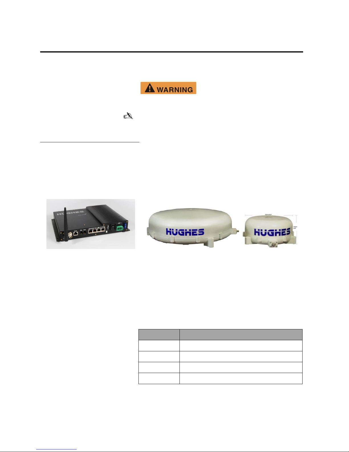
Figure 1-1. 9450 IDU (left) and Class 10 antenna (middle) Class 11 antenna (right) .............................. 4
Figure 1-2. 9450 Indoor Unit (IDU) ........................................................................................................ 5
Figure 1-3. Inserting SIM card in the SIM card holder............................................................................ 8
Figure 3-1. Chassis ground .................................................................................................................... 10
Figure 5-1. Common Indoor Unit mounting dimensions ....................................................................... 13
Figure 5-2 Charge Guard Features ........................................................................................................ 14
Figure 5-3 Charge Guard Wiring Diagram ........................................................................................... 15
Figure 5-4 Charge Guard Guide............................................................................................................ 15
Figure 6-1. C10 antenna unit ................................................................................................................. 16
Figure 6-2 C11 antenna unit ................................................................................................................. 16
Tables
Table 1. 9450 Variants ............................................................................................................................. 4
Table 2. Power port pin out ...................................................................................................................... 5
Table 3. RJ-45 Ethernet port pinout ......................................................................................................... 6
Table 4. ISDN port pin out....................................................................................................................... 7
Table 5. RJ-11 port pinout ....................................................................................................................... 7
Table 6. System power requirements ....................................................................................................... 9
Table 7. Power cable pinout ..................................................................................................................... 9
Table 8. Package materials .................................................................................................................... 11
2
3004129-0001 Revision E
Understanding safety alert messages
WARNING indicates a potentially hazardous situation, which if
not avoided, could result in death or serious injury.
CAUTION indicates a potentially hazardous situation, which if
not avoided, could result in minor or moderate injury.
Messages concerning
personal injury
Safety alert messages call attention to potential safety hazards
and tell you how to avoid them. These messages are identified
by the signal words WARNING or CAUTION, as illustrated
below. To avoid possible property damage, personal injury, or in
some cases possible death, read and comply with all safety alert
messages.
The signal words WARNING and CAUTION indicate hazards
that could result in personal injury or in some cases death, as
explained below. Each of these signal words indicates the
severity of the potential hazard.
The generic safety alert symbol calls attention to a
potential personal injury hazard. It appears next to the
WARNING and CAUTION signal words as part of the signal
word label. Other symbols may appear next to WARNING or
CAUTION to indicate a specific type of hazard (for example,
fire or electric shock).
Safety symbols
3
3004129-0001 Revision E
Chapter 1 Introduction
This product must be installed by Authorized Service Personnel.
Note: Damages resulting in the failure to conform to the
instructions found herein, as well as standard installation
practices, will be the responsibility of the installer.
9450 Version
Interfaces
9450
Ethernet (with PoE), POTS, ISDN, WLAN
9450E
Ethernet (with PoE), POTS, ISDN
9450T
Ethernet (with PoE), POTS
9450L
Ethernet
The purpose of this guide is to provide assistance to personnel
installing the Hughes 9450 mobile satellite terminal into a
vehicle.
Hughes 9450 mobile
satellite terminals
The mobile satellite terminals are composed of four parts: the
transceiver or Indoor Unit (IDU), the antenna or Outdoor Unit
(ODU), the power connector/cable, and a 10 meter RF cable.
Figure 1-1. 9450 IDU (left) and Class 10 antenna (middle) Class 11 antenna (right)
The Hughes IDU has multiple interfaces that various Terminal
Equipment (TE) devices such as laptops, phones, etc., can
connect to: four PoE/Ethernet (RJ-45), ISDN, two POTS
(RJ-11) and Wireless Local Area Network (WLAN).
There are multiple versions of the 9450. The IDU housing is
common but the different versions have different user interfaces.
Table 1. 9450 Variants
4
3004129-0001 Revision E
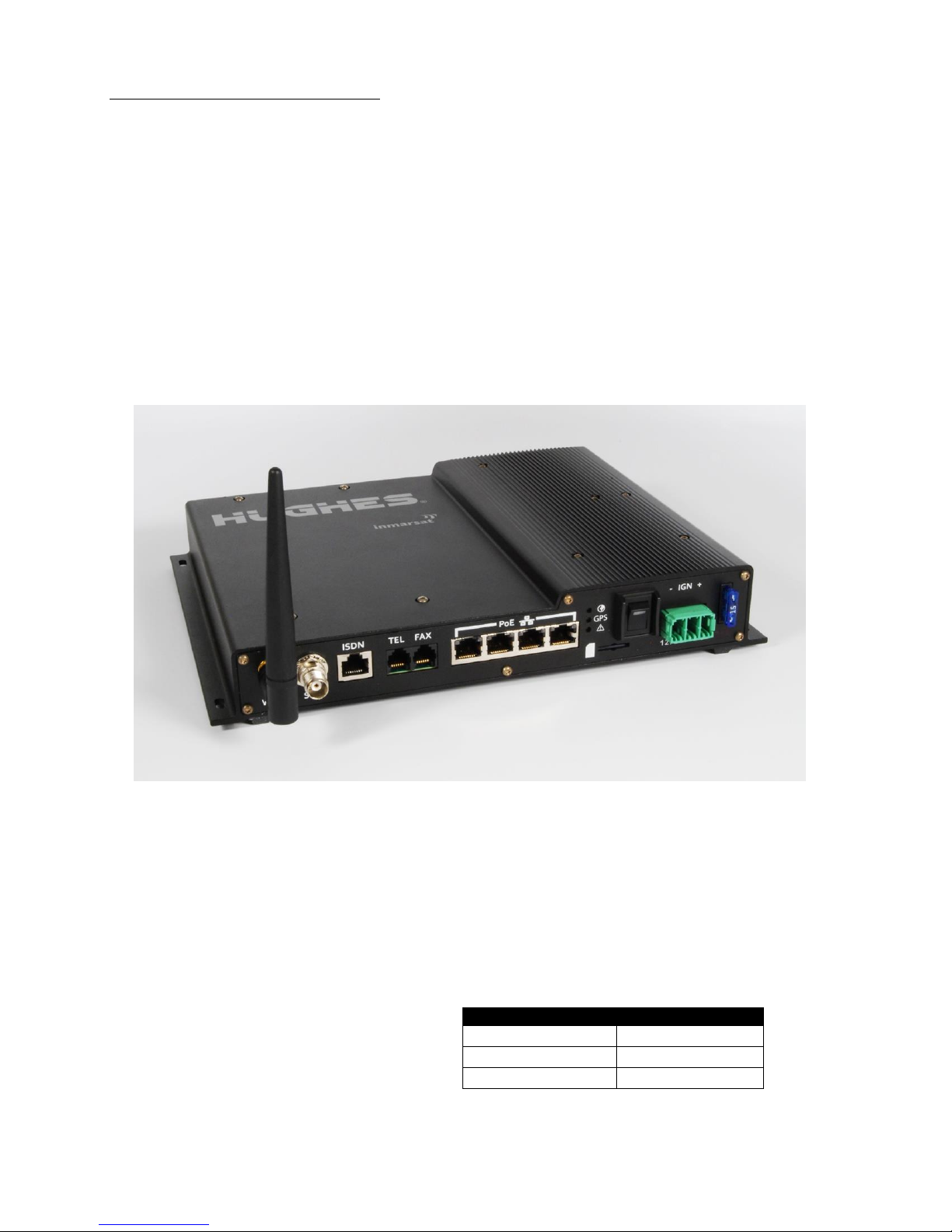
Indoor Unit (IDU)
Table 2. Power port pin out
Line type
Pin number
+V power line
1
Ignition Sense
2
-V power line
3
Physical dimensions
The IDU provides all of the TE interfaces, plus the interface for
the antenna (ODU) and manages the communications over the
Inmarsat BGAN network. Communication to the ODU is
provided by the RF cable from the IDU.
IDU: Size: 46 mm x 281 mm x 233 mm
Weight: 2.2 kg
RF cable: 10 meter coaxial LMR195 or equivalent (<10 dB
loss@ 1.6GHz and 50 Ohm impedance), TNC
connectors
Power port
Figure 1-2. 9450 Indoor Unit (IDU)
The power port is the connection from the power supply (vehicle
battery or some other 12 or 24 Vdc power source) to the IDU.
The power cable has a +V power line, an ignition sense line and
a –V power line.
5
3004129-0001 Revision E

4X RJ-45 Ethernet with Power over Ethernet (PoE) ports
Table 3. RJ-45 Ethernet port pinout
Pin
1
RX+ 2 RX-
3
TX+
4
NC 5 NC 6 TX- 7 NC 8 NC
Note: The 48 Vdc for PoE devices is supplied over the TX, RX
pairs. They are only active when an 802.3af compliant device is
plugged in. The other pairs (4, 5, 7, and 8) are unused.
Note: Class 4 (802.3at) PD devices are not supported.
There are four RJ-45 ports with Power over Ethernet (PoE) on the
IDU. (The 9450L does not have PoE.) The ports supply standard
PoE according to the IEEE 802.3af standard (48 Vdc up to
15.4 W) and 10/100BaseT Ethernet. The pinout of the ports
supports a direct straight-through connection to a PC with a
standard Ethernet cable. Table 3, shows the pinout of the Ethernet
connector.
ISDN port
The total power supplied by the PoE is limited to 30.8 W
maximum for 12 V installations and 61.6 W maximum for 24 V
installations. The IDU automatically detects the class of the
device plugged in and will apply power such that the total cannot
exceed these limits. If the user attempts to connect a combination
of devices that require more than this, the IDU will not power
any devices that would cause the limit to be exceeded.
There is one ISDN port on the IDU of the 9450 and 9450E. It
provides 4 kbps voice, 3.1 kHz audio, and 64 kbps data
communication. The following table lists the pinout of the ISDN
connector.
6
3004129-0001 Revision E
 Loading...