


 Loading...
HP Z220 SFF, Z220 CMT, Z420, Z620,
and Z820 Workstations
Maintenance and Service Guide
Copyright Information
© Copyright 2012, 2013 Hewlett-Packard
Development Company, L.P
Third Edition: February 2013
First Edition: April 2012
669531-003
Warranty
Hewlett-Packard Company shall not be liable for technical or editorial errors or omissions contained herein or for incidental or consequential damages in connection with the furnishing, performance, or use of this material. The information in this document is provided “as is” without warranty of any kind, including, but not limited to, the implied warranties of merchantability and fitness for a particular purpose, and is subject to change without notice. The warranties for HP products are set forth in the express limited warranty statements accompanying such products.
Nothing herein should be construed as constituting an additional warranty.
The information contained herein is subject to change without notice. The only warranties for HP products and services are set forth in the express warranty statements accompanying such products and services. Nothing herein should be construed as constituting an additional warranty. HP shall not be liable for technical or editorial errors or omissions contained herein.
Trademark Credits
Windows is a U.S. registered trademark of Microsoft Corporation.
Intel, Core, Pentium, and Xeon are trademarks are trademarks of Intel Corporation in the U.S. and other countries.
FireWire is a trademark of Apple Computer, Inc., registered in the U.S. and other countries.
ENERGY STAR is a registered trademark owned by the U.S. Environmental Protection Agency (EPA).

About this guide
This guide provides service and maintenance information, technical details and configuration guidance for the HP Z220 SFF, Z220 CMT, Z420, Z620, and Z820 Workstations.


 IMPORTANT: Removal and replacement procedures are now available in videos on the HP website.
Go to the HP Customer Self-Repair Services Media Library at http://www.hp.com/go/sml.
Guide topics
Hardware overview on page 1
System management on page 39
Component replacement information and guidelines on page 77
Diagnostics and troubleshooting on page 116
Configuring password security and resetting CMOS on page 159
Linux technical notes on page 163
Configuring RAID devices on page 167
System board designators on page 179


 NOTE: View the HP Z220 SFF, Z220 CMT, Z420, Z620, and Z820 Workstation Series User Guide at http://www.hp.com/support/workstation_manuals.
iii

Table of contents
1 Hardware overview ......................................................................................................... |
1 |
HP Z220 SFF Workstation components ....................................................................................... |
1 |
HP Z220 SFF Workstation front panel components ........................................................ |
2 |
HP Z220 SFF Workstation rear panel components ........................................................ |
3 |
HP Z220 SFF Workstation chassis components ............................................................. |
4 |
HP Z220 SFF Workstation system board component ...................................................... |
5 |
HP Z220 SFF Workstation system board architecture ..................................................... |
6 |
Workstation specifications .......................................................................................... |
7 |
HP Z220 CMT Workstation components ..................................................................................... |
8 |
HP Z220 CMT Workstation front panel components ...................................................... |
9 |
HP Z220 CMT Workstation rear panel components .................................................... |
10 |
HP Z220 CMT Workstation chassis components ......................................................... |
11 |
HP Z220 CMT Workstation system board component .................................................. |
12 |
HP Z220 CMT Workstation system board architecture ................................................. |
13 |
Workstation specifications ........................................................................................ |
14 |
HP Z420 Workstation components ........................................................................................... |
15 |
HP Z420 Workstation front panel ............................................................................. |
16 |
HP Z420 Workstation rear panel .............................................................................. |
17 |
HP Z420 Workstation chassis components ................................................................. |
18 |
HP Z420 Workstation system board components ........................................................ |
19 |
HP Z420 Workstation system board architecture ......................................................... |
20 |
HP Z420 Workstation specifications .......................................................................... |
21 |
HP Z620 Workstation components ........................................................................................... |
23 |
HP Z620 Workstation front panel ............................................................................. |
23 |
HP Z620 Workstation rear panel .............................................................................. |
24 |
HP Z620 Workstation chassis components ................................................................. |
25 |
HP Z620 Workstation system board components ........................................................ |
26 |
HP Z620 Workstation system board architecture ......................................................... |
27 |
HP Z620 Workstation specifications .......................................................................... |
28 |
HP Z820 Workstation components ........................................................................................... |
30 |
HP Z820 Workstation front panel ............................................................................. |
30 |
HP Z820 Workstation rear panel .............................................................................. |
31 |
HP Z820 Workstation chassis components ................................................................. |
32 |
HP Z820 Workstation system board components ........................................................ |
33 |
HP Z820 Workstation system board architecture ......................................................... |
34 |
HP Z820 Workstation specifications .......................................................................... |
35 |
v
Environmental specifications .................................................................................................... |
37 |
ENERGY STAR qualification .................................................................................................... |
37 |
Ensuring proper ventilation ...................................................................................................... |
38 |
2 System management ...................................................................................................... |
39 |
Power management and performance features .......................................................................... |
39 |
ERP compliance mode ............................................................................................. |
39 |
Hyper-Threading Technology (HTT) ............................................................................ |
40 |
SATA Power Management ....................................................................................... |
40 |
Intel Turbo Boost Technology .................................................................................... |
40 |
HP Cool Tools (Windows 7 only) .............................................................................. |
40 |
Non-Uniform Memory Access (NUMA) ...................................................................... |
41 |
BIOS ROM ............................................................................................................................ |
41 |
Computer Setup (F10) Utility .................................................................................................... |
42 |
Computer Setup (F10) functionality ............................................................................ |
42 |
Accessing Computer Setup (F10) Utility ...................................................................... |
43 |
Computer Setup (F10) Utility menu ............................................................................ |
44 |
Desktop management ............................................................................................................. |
60 |
Initial computer configuration and deployment ............................................................ |
61 |
Installing a remote system ......................................................................................... |
61 |
Copying a setup configuration to another computer ..................................................... |
62 |
Updating and managing software ............................................................................. |
63 |
HP Client Management Solutions .............................................................................. |
63 |
Altiris Client Management Solutions .......................................................................... |
63 |
HP SoftPaq Download Manager ............................................................................... |
64 |
System Software Manager ....................................................................................... |
64 |
ROM Flash ............................................................................................................. |
64 |
Remote ROM Flash ................................................................................... |
64 |
HPQFlash ................................................................................................ |
64 |
FailSafe Boot Block .................................................................................................. |
64 |
Recovering the computer from Boot Block Recovery mode ............................. |
65 |
Workstation security ................................................................................................ |
65 |
Asset tracking .......................................................................................... |
66 |
SATA hard disk drive security .................................................................... |
67 |
DriveLock applications ............................................................... |
68 |
Using DriveLock ........................................................................ |
68 |
Password security ..................................................................................... |
70 |
Establishing a setup password using Computer Setup (F10) Utility ... |
70 |
Establishing a power-on password using computer setup ................ |
71 |
Entering a power-on password .................................................... |
71 |
Entering a setup password ......................................................... |
72 |
vi
|
Changing a power-on or setup password ..................................... |
72 |
|
Deleting a power-on or setup password ....................................... |
73 |
|
National keyboard delimiter characters ....................................... |
73 |
|
Clearing passwords ................................................................... |
74 |
Chassis security ....................................................................................... |
74 |
|
|
Smart Cover Sensor (optional) .................................................... |
74 |
|
Side access panel solenoid lock .................................................. |
75 |
|
Cable lock (optional) ................................................................. |
75 |
Fault notification and recovery .................................................................................. |
75 |
|
Drive Protection System ............................................................................. |
75 |
|
ECC fault prediction ................................................................................. |
75 |
|
Thermal sensors ....................................................................................... |
75 |
|
Programmable power button (Windows only) ............................................................. |
76 |
|
Changing the power button configuration (Windows only) ............................ |
76 |
|
3 Component replacement information and guidelines ....................................................... |
77 |
|
Warnings and cautions ........................................................................................................... |
|
78 |
Service considerations ............................................................................................................ |
|
79 |
Tools and software requirements ............................................................................... |
79 |
|
Electrostatic discharge (ESD) information .................................................................... |
79 |
|
Product recycling ................................................................................................................... |
|
81 |
Component replacement guidelines .......................................................................................... |
81 |
|
Battery ................................................................................................................... |
|
81 |
Cable management ................................................................................................. |
|
82 |
CPU (processor) and CPU heatsink ............................................................................ |
83 |
|
Expansion slots ....................................................................................................... |
|
84 |
Card configuration restrictions for power supplies ........................................ |
84 |
|
Choosing an expansion card slot ............................................................... |
84 |
|
HP Z220 |
SFF Workstation slot identification and description ......................... |
85 |
HP Z220 |
SFF Workstation installation sequence recommendations ................. |
86 |
HP Z220 |
CMT Workstation slot identification and description ....................... |
87 |
HP Z220 |
CMT Workstation installation sequence recommendations ............... |
88 |
HP Z420 |
Workstation slot identification and description ............................... |
89 |
HP Z420 |
Workstation installation sequence recommendations ....................... |
90 |
HP Z620 |
Workstation slot identification and description ............................... |
91 |
HP Z620 |
Workstation installation sequence recommendations ....................... |
92 |
HP Z820 |
Workstation slot identification and description ............................... |
93 |
HP Z820 |
Workstation installation sequence recommendations ....................... |
94 |
Hard disk drives and optical disc drives ..................................................................... |
95 |
|
Handling hard disk drives ......................................................................... |
95 |
|
Removal and replacement tips ................................................................... |
95 |
|
vii
Drive installation and cabling scenarios ...................................................... |
96 |
HP Z220 SFF Workstations — SATA cable connection guidelines ... |
96 |
HP Z220 CMT Workstations — SATA cable connection |
|
guidelines ................................................................................ |
96 |
HP Z420 Workstations — Intel AHCI SATA controller guidelines ..... |
97 |
HP Z420 Workstations — LSI 9212-4i RAID controller guidelines .... |
98 |
HP Z620 Workstations — Intel AHCI SATA controller guidelines ..... |
99 |
HP Z620 Workstations — LSI 9212-4i RAID controller guidelines .. |
100 |
HP Z820 Workstation cabling guidelines ................................... |
101 |
Memory ............................................................................................................... |
102 |
Supported DIMM configurations ............................................................... |
102 |
BIOS errors and warnings ....................................................................... |
103 |
DIMM installation guidelines .................................................................... |
103 |
HP Z220 SFF Workstation DIMM installation order .................................... |
104 |
HP Z220 CMT Workstation DIMM installation order ................................... |
104 |
HP Z420 Workstation DIMM installation order .......................................... |
105 |
HP Z620 Workstation DIMM installation order .......................................... |
106 |
HP Z820 Workstation DIMM installation order .......................................... |
107 |
Power supply ........................................................................................................ |
108 |
Power supply specifications ..................................................................... |
108 |
Power consumption and heat dissipation ................................................... |
110 |
Resetting the power supply ...................................................................... |
110 |
System board ....................................................................................................... |
110 |
System cabling ...................................................................................... |
111 |
HP Z220 SFF Workstation system cabling .................................. |
111 |
HP Z220 CMT Workstation system cabling ................................ |
112 |
HP Z420 Workstation system cabling ........................................ |
113 |
HP Z620 Workstation system cabling ........................................ |
114 |
HP Z820 Workstation system cabling ........................................ |
115 |
4 Diagnostics and troubleshooting ................................................................................... |
116 |
Calling support .................................................................................................................... |
117 |
Locating ID labels ................................................................................................................. |
118 |
Locating warranty information ............................................................................................... |
119 |
Diagnosis guidelines ............................................................................................................ |
119 |
Diagnosis at startup ............................................................................................... |
119 |
Diagnosis during operation .................................................................................... |
120 |
Troubleshooting checklist ....................................................................................................... |
121 |
HP troubleshooting resources and tools ................................................................................... |
122 |
HP Support Assistant .............................................................................................. |
122 |
Online support ...................................................................................................... |
122 |
viii
Troubleshooting a problem ...................................................................... |
123 |
Instant Support and Active Chat ............................................................... |
123 |
Customer Advisories, Customer and Security Bulletins, and Customer Notices |
123 |
Product Change Notifications .................................................................. |
123 |
Helpful hints ......................................................................................................... |
124 |
At startup .............................................................................................. |
124 |
During operation .................................................................................... |
124 |
Customer Self-Repair program ................................................................. |
125 |
Troubleshooting scenarios and solutions .................................................................................. |
126 |
Solving minor problems ......................................................................................... |
126 |
Solving hard drive problems ................................................................................... |
128 |
Solving display problems ....................................................................................... |
130 |
Solving audio problems ......................................................................................... |
132 |
Solving printer problems ........................................................................................ |
133 |
Solving power supply problems .............................................................................. |
134 |
Testing power supply .............................................................................. |
134 |
Self-troubleshooting with HP Vision Diagnostics ........................................................................ |
136 |
Overview ............................................................................................................. |
136 |
Downloading and accessing HP Vision Diagnostics ................................................... |
137 |
Accessing HP Vision Diagnostics on the computer ..................................................... |
137 |
Creating and using a bootable USB key ................................................... |
138 |
Creating and using a bootable DVD ......................................................... |
138 |
Using the HP Memory Test utility .............................................................. |
138 |
User interface ....................................................................................................... |
139 |
Survey tab ............................................................................................. |
140 |
Test tab ................................................................................................. |
141 |
Status tab .............................................................................................. |
142 |
History tab ............................................................................................ |
142 |
Errors tab .............................................................................................. |
143 |
Help tab ............................................................................................... |
143 |
Saving and printing information in HP Vision Diagnostics ........................................... |
144 |
Self-troubleshooting with HP PC Hardware Diagnostics ............................................................. |
145 |
Downloading HP PC Hardware Diagnostics ............................................................. |
146 |
Accessing HP PC Hardware Diagnostics .................................................................. |
147 |
User interface ....................................................................................................... |
147 |
Running HP PC Hardware Diagnostics ..................................................................... |
148 |
System information ................................................................................. |
148 |
Hardware diagnostic tests ....................................................................... |
149 |
Diagnostic codes and errors .................................................................................................. |
150 |
Diagnostic LED and audible (beep) codes ................................................................ |
150 |
LED color definitions .............................................................................................. |
154 |
ix
POST error messages ............................................................................................ |
154 |
5 Configuring password security and resetting CMOS ...................................................... |
159 |
Preparing to configure passwords .......................................................................................... |
159 |
Resetting the password jumper ............................................................................................... |
160 |
Clearing and resetting the CMOS .......................................................................................... |
161 |
Using the CMOS button to reset CMOS ................................................................... |
161 |
Using Computer Setup (F10) Utility to reset CMOS .................................................... |
162 |
Appendix A Linux technical notes .................................................................................... |
163 |
System RAM ........................................................................................................................ |
163 |
Audio ................................................................................................................................. |
163 |
Network cards ..................................................................................................................... |
164 |
Hyper-Threading Technology ................................................................................................. |
164 |
NVIDIA Graphics Workstations ............................................................................................. |
165 |
AMD Graphics Workstations ................................................................................................. |
166 |
Appendix B Configuring RAID devices .............................................................................. |
167 |
RAID hard drive maximum and associated storage controller options ......................................... |
167 |
Supported RAID configurations .............................................................................................. |
168 |
Configuring Intel SATA RAID ................................................................................................. |
169 |
Configuring system BIOS ....................................................................................... |
170 |
Configuring RAID with the Intel utility ....................................................................... |
171 |
Configuring RAID on an LSI 2308 or LSI 9212-4i controller ....................................................... |
172 |
RAID 0 configuration ............................................................................................. |
172 |
RAID 1 configuration ............................................................................................. |
173 |
RAID 1E/10 configuration ..................................................................................... |
174 |
Configuring RAID on an LSI 9260-8i MegaRAID controller ........................................................ |
175 |
RAID 0 ................................................................................................................. |
175 |
Software RAID solution ......................................................................................................... |
177 |
Software RAID considerations ................................................................................. |
177 |
Performance considerations .................................................................................... |
177 |
Configuring software RAID ..................................................................................... |
178 |
Appendix C System board designators ............................................................................ |
179 |
HP Z220 SFF Workstation ..................................................................................................... |
179 |
HP Z220 CMT Workstation ................................................................................................... |
180 |
HP Z420 and Z620 Workstation system board designators ...................................................... |
181 |
HP Z820 Workstations ......................................................................................................... |
183 |
x
Index ............................................................................................................................... |
186 |
xi
1 Hardware overview
This chapter presents an overview of workstation hardware components.
Topics
HP Z220 SFF Workstation components on page 1
HP Z220 CMT Workstation components on page 8
HP Z420 Workstation components on page 15
HP Z620 Workstation components on page 23
HP Z820 Workstation components on page 30
Environmental specifications on page 37
ENERGY STAR qualification on page 37
Ensuring proper ventilation on page 38
HP Z220 SFF Workstation components
For complete and current information on supported accessories and components for the workstation, see http://partsurfer.hp.com.
Topics
HP Z220 SFF Workstation front panel components on page 2
HP Z220 SFF Workstation rear panel components on page 3
HP Z220 SFF Workstation chassis components on page 4
HP Z220 SFF Workstation system board component on page 5
HP Z220 SFF Workstation system board architecture on page 6
Workstation specifications on page 7
HP Z220 SFF Workstation components |
1 |
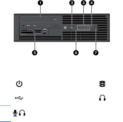
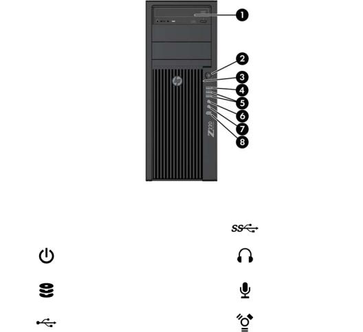
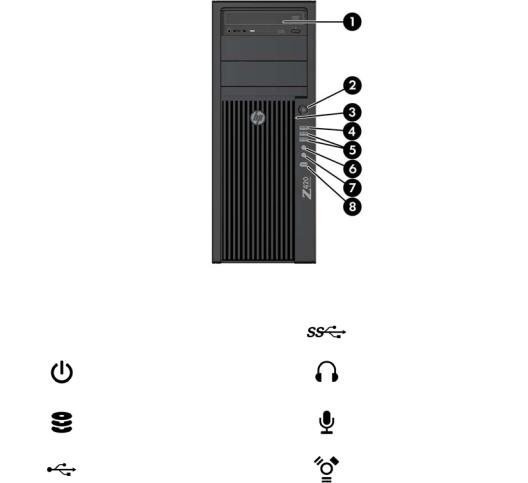
HP Z220 SFF Workstation front panel components
Figure 1-1 Front panel components
Table 1-1 |
Component description |
|
|
|
|
|
|
|
|
1 |
Optical drive |
5 |
Optional media card reader (shown) |
|
or optional second hard disk drive |
||||
|
|
|
||
|
|
|
|
|
2 |
Power button |
6 |
Hard drive or optical drive activity |
|
light |
||||
|
|
|
||
|
|
|
|
|
3 |
USB 2.0 ports (4, black) |
7 |
Headphones connector |
Microphone or headphones connector
4(software selectable, default mode is microphone)
2 Chapter 1 Hardware overview
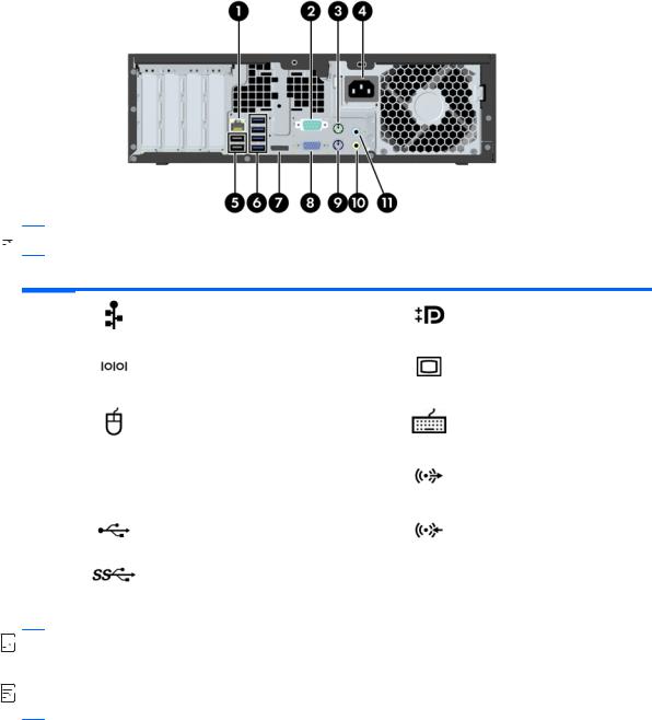
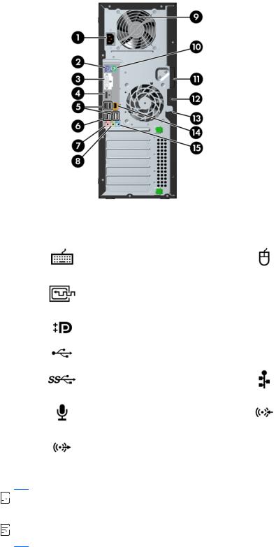
HP Z220 SFF Workstation rear panel components
Figure 1-2 Rear panel components
 NOTE: The labels for the rear panel connectors use industry-standard icons and colors.
Table 1-2 Component descriptions
1 |
RJ–45 network connector |
7 |
DisplayPort (DP) |
||
|
|
|
|
|
|
2 |
Serial port |
|
8 |
VGA (monitor) (blue) |
|
|
|
||||
|
|
|
|
|
|
3 |
PS/2 mouse connector (green) |
9 |
PS/2 keyboard connector |
||
(purple) |
|||||
|
|
|
|
||
|
|
|
|
||
4 |
Power cord connector |
10 |
Audio line-out connector (green) |
||
|
|
|
|
|
|
5 |
USB 2.0 ports (2) |
(back) |
11 |
Audio line-in connector (blue) |
|
|
|
|
|
|
|
6 |
USB 3.0 ports (4) |
(blue) |
|
|
|
|
|
|
|
|
|


 NOTE: The DP and VGA ports are not supported when the system is configured with Intel® Xeon® E3-12x0 v2 processors. Also, if a discrete graphics card is installed, these ports are disabled by default.


 NOTE: Simultaneous usage of integrated Intel HD graphics and discrete graphics cards (in order to drive more than two displays) can be enabled using the Computer (F10) Setup Utility. However, HP recommends using only discrete graphics cards when attaching three or more displays.
HP Z220 SFF Workstation components |
3 |
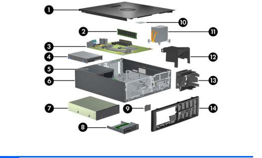
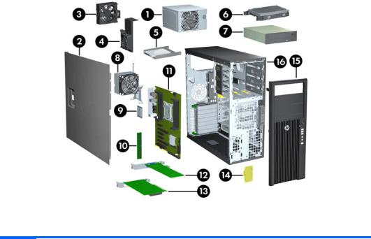
HP Z220 SFF Workstation chassis components
For complete and current information on supported accessories and components for the computer, see http://partsurfer.hp.com.
The following image shows the components of a typical computer layout. Drive configurations can vary. Figure 1-3 Chassis components
Table 1-3 Component descriptions
1 |
Access panel |
8 |
Optional media reader or second hard disk drive |
|
|
|
|
2 |
Memory module (DIMM) |
9 |
Speaker |
|
|
|
|
3 |
System board |
10 |
CPU |
|
|
|
|
4 |
Hard disk drive |
11 |
Heatsink |
|
|
|
|
5 |
Power supply |
12 |
Airflow guide |
|
|
|
|
6 |
Chassis |
13 |
System fan |
|
|
|
|
7 |
Optical drive |
14 |
Front bezel |
|
|
|
|
4 Chapter 1 Hardware overview
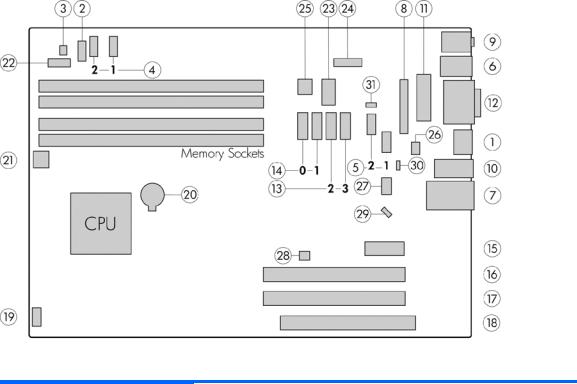
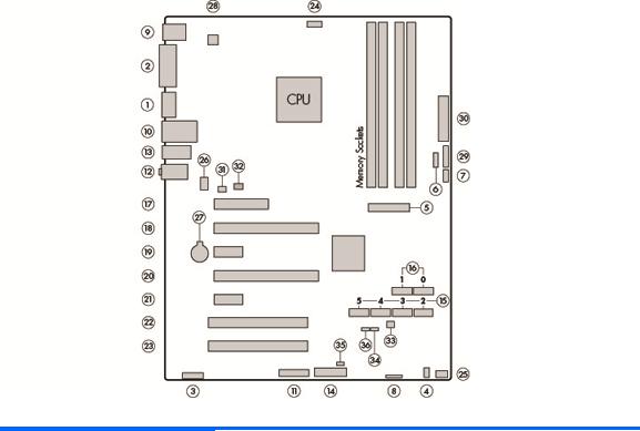
HP Z220 SFF Workstation system board component
The following illustration and table identify computer system board components.
Figure 1-4 System board component locations
Table 1-4 System board component descriptions
|
I/O |
|
SATA |
|
Power |
|
|
|
|
|
|
|
|
1 |
Display Port |
13 |
AHCI 3Gb/s |
20 |
Battery |
|
|
|
|
|
|
|
|
2 |
Front audio |
14 |
AHCI 6Gb/s |
21 |
CPU power |
|
|
|
|
|
|
||
3 |
Front speaker |
NOTE: Only the port labeled |
22 |
Front power button/LED |
||
|
|
eSATA is eSATA compatible. |
|
|
||
4 |
Front USB 2.0 |
23 |
Main power |
|||
|
|
|||||
|
|
|
|
|
|
|
5 |
Internal USB 2.0 |
|
PCI/PCIe |
24 |
Power COMM |
|
|
|
|
|
|
|
|
6 |
Keyboard/mouse |
15 |
PCIe2 x1 |
25 |
SATA power |
|
|
|
|
|
|
|
|
7 |
Network/rear USB 2.0 |
16 |
PCIe2 x16 (4) |
|
Security |
|
|
|
|
|
|
|
|
8 |
Parallel (optional) |
17 |
PCIe3 x16 |
26 |
Chassis solenoid lock |
|
|
|
|
|
|
|
|
9 |
Rear audio |
18 |
PCI 32/33 |
27 |
Hood sense |
|
|
|
|
|
|
||
10 |
Rear USB 3.0 |
NOTE: For related expansion |
|
Service |
||
|
|
|
card slot information, see |
|
|
|
11 |
Serial (optional) |
|
28 |
Clear CMOS button |
||
Expansion slots on page 84 |
||||||
|
|
|
|
|
|
|
12 |
VGA/serial |
|
Cooling |
29 |
Crisis recovery jumper |
|
|
|
|
|
|
|
|
|
|
19 |
Chassis fan |
30 |
ME/AMT flash override |
|
|
|
|
|
|
|
|
|
|
|
|
31 |
Password jumper |
|
|
|
|
|
|
|
|
HP Z220 SFF Workstation components |
5 |
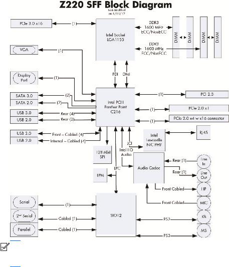
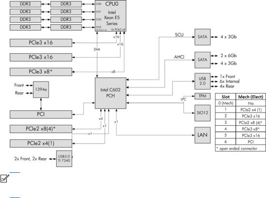
HP Z220 SFF Workstation system board architecture
This section describes the system architectures.
The following figure shows the typical system board block diagram.
Figure 1-5 System board block diagram


 NOTE: The PCIe designators indicate the mechanical connector size and number of electrical PCIe lanes routed to an expansion slot. For example, x16(8) means that the expansion slot is mechanically a x16 length connector, with 8 PCIe lanes supported.
6 Chapter 1 Hardware overview

Workstation specifications
HP Z220 SFF
|
Intel Series C216 chipset: |
|
|
● Support for the Intel® Xeon® Processor E3 v2 Family, third-generation Intel Core processors up to |
|
|
95 W, or Intel Pentium® G640 procesors |
|
Processor |
● Integrated 2-channel memory controller |
|
|
||
technology |
● Microarchitecture improvements |
|
|
● Integrated graphics (some models) |
|
|
● Advanced Vector Extensions (AVX) to increase floating point performance |
|
|
● Intel DMI2 interface connecting the processor to the I/O controller |
|
|
|
|
Power supply |
● 240 W, 90% efficient, 80 PLUS Gold, compatible with ENERGY STAR® Version 5 requirements |
|
● Supports European Union ERP Lot 6 tier2 power limit of less than 0.5W in off mode |
||
|
||
|
|
|
|
● Dual in-line memory modules (DIMMs) based on DDR3 1600 MHz technology |
|
|
● Supports error checking and correcting (ECC) and non-ECC DIMMs |
|
Memory |
● Two direct-attach memory channels enable low-latency access and fast data transfer for improved |
|
performance |
||
technology |
● Up to 32 GB system memory (8 GB DIMMs) |
|
|
||
|
● 1600 MHz 2, 4, 8 GB ECC unbuffered DIMM |
|
|
● 1600 MHz 2, 4, 8 GB non ECC unbuffered DIMM |
|
|
|
|
|
Supports: |
|
|
● PCIe Gen3 (PCIe3) bus speeds; can support dual PCIe Gen2 graphics cards in mechanical PCIe |
|
|
x16 slots |
|
|
● Multiple graphics cards, provided their total power usage is within 45 W |
|
Graphics cards |
● Up to two displays with integrated Intel HD graphics (depending on processor type) |
|
● Up to four 2D displays or two 3D displays |
||
|
NOTE: Most supported Intel Core processors provide Intel HD Graphics 2000/2500/4000; Intel |
|
|
Xeon processors with model designations that end in "---5" provide Intel HD Graphics P4000. |
|
|
NOTE: To drive more than two displays, use the Computer (F10) Setup Utility to intermix integrated |
|
|
Intel HD graphics and discrete graphics cards (with three or more displays, HP recommends using only |
|
|
discrete graphics cards). |
|
|
|
|
|
● RAID configurations for SATA RAID levels 0, 1 |
|
|
● Supports eSATA (3.0 Gbps) using an optional adapter |
|
I/O technology |
● Six external and four internal USB 2.0 ports |
|
|
● Four external USB 3.0 ports |
|
|
● Parallel and serial headers that can be used with an optional PCI bulkhead connector |
|
|
|
HP Z220 SFF Workstation components |
7 |

HP Z220 CMT Workstation components
For complete and current information on supported accessories and components for the computer, see http://partsurfer.hp.com.
Topics
HP Z220 CMT Workstation front panel components on page 9
HP Z220 CMT Workstation rear panel components on page 10
HP Z220 SFF Workstation chassis components on page 4
HP Z220 SFF Workstation system board component on page 5
HP Z220 SFF Workstation system board architecture on page 6
8 Chapter 1 Hardware overview
HP Z220 CMT Workstation front panel components
Figure 1-6 Front panel components
Table 1-5 |
Component descriptions |
|
|
|
|
|
|
|
|
1 |
Optical drive |
5 |
USB 3.0 ports (2) (blue) |
|
|
|
|
|
|
2 |
Power button |
6 |
Headphone connector |
|
|
|
|
|
|
3 |
Hard drive activity light |
7 |
Microphone connector |
|
|
|
|
|
|
4 |
USB 2.0 ports (1) (black) |
8 |
1394a FireWire® connector (optional |
|
and plugged unless configured) |
||||
|
|
|
||
|
|
|
|
HP Z220 CMT Workstation components |
9 |
HP Z220 CMT Workstation rear panel components
Figure 1-7 Rear panel components
Table 1-6 |
Component descriptions |
|
|
|
|
|
|
|
|
1 |
Power cord connector |
9 |
Power supply Built-In Self Test (BIST) LED |
|
|
|
|
|
|
2 |
PS/2 keyboard connector (purple) |
10 |
PS/2 mouse connector (green) |
|
|
|
|
|
|
3 |
DVI-I connector |
|
11 |
Universal chassis clamp opening |
|
|
|
|
|
4 |
Display Port (DP) connector |
12 |
Cable lock slot |
|
|
|
|
|
|
5 |
USB 2.0 ports (4) |
(black) |
13 |
Padlock loop |
|
|
|
|
|
6 |
USB 3.0 ports (2) |
(blue) |
14 |
RJ-45 network connector |
|
|
|
|
|
7 |
Microphone connector (pink) |
15 |
Audio line-in connector (blue) |
|
|
|
|
|
|
8 |
Audio line-out connector (green) |
|
|
|
|
|
|
|
|


 NOTE: The DP and DVI-I ports are not supported when the system is configured with Intel Xeon E3-12x0 v2 processors. Also, if a discrete graphics card is installed these ports are disabled by default.


 NOTE: Simultaneous usage of integrated Intel HD graphics and discrete graphics cards (in order to drive more than two displays) can be enabled using the Computer (F10) Setup Utility. However, HP recommends using only discrete graphics cards when attaching three or more displays.
10 Chapter 1 Hardware overview
HP Z220 CMT Workstation chassis components
The following figure shows the chassis components of a typical HP Z220 CMT Workstation layout. Drive configurations can vary.
Figure 1-8 Chassis components
Table 1-7 Workstation component descriptions
Item |
Description |
Item |
Description |
|
|
|
|
1 |
Power supply |
8 |
Memory module (DIMM) |
|
|
|
|
2 |
Side access panel |
9 |
PCIe card |
|
|
|
|
3 |
Rear system fan |
10 |
PCI card |
|
|
|
|
4 |
Optical drive |
11 |
Speaker |
|
|
|
|
5 |
CPU heatsink |
12 |
Hard disk drive |
|
|
|
|
6 |
CPU |
13 |
Front bezel |
|
|
|
|
7 |
System board |
14 |
Chassis |
|
|
|
|
HP Z220 CMT Workstation components |
11 |
HP Z220 CMT Workstation system board component
The following illustration and table identify workstation system board components.
Figure 1-9 System board component locations
Table 1-8 System board component descriptions
|
I/O |
|
SATA |
|
Power |
|
|
|
|
|
|
1 |
Display Port |
15 |
AHCI 3Gb/s |
27 |
Battery |
|
|
|
|
|
|
2 |
DVI video |
16 |
AHCI 6Gb/s |
28 |
CPU power |
|
|
|
|
|
|
3 |
Front audio |
|
PCI/PCIe |
29 |
Front power button/LED |
|
|
|
|
|
|
4 |
Front speaker |
17 |
PCIe2 x8 (4) |
30 |
Main power |
|
|
|
|
|
|
5 |
Front USB 2.0/3.0 |
18 |
PCIe3 x16 |
|
Security |
|
|
|
|
|
|
6 |
Internal USB 2.0 |
19 |
PCIe2 x1 |
31 |
Chassis solenoid lock |
|
|
|
|
|
|
7 |
Internal USB 2.0 |
20 |
PCIe2 x16 (4) |
32 |
Hood sense |
|
|
|
|
|
|
8 |
Internal USB 2.0 |
21 |
PCIe2 x1 |
|
Service |
|
|
|
|
|
|
9 |
Keyboard/mouse |
22 |
PCI 32/33 |
33 |
Clear CMOS button |
|
|
|
|
|
|
10 |
Network/rear USB 2.0 |
23 |
PCI 32/33 |
34 |
Crisis recovery jumper |
|
|
|
|
|
|
11 |
Parallel (optional) |
|
Cooling |
35 |
ME/AMT flash override |
|
|
|
|
|
|
12 |
Rear audio |
24 |
CPU fan |
36 |
Password jumper |
|
|
|
|
|
|
13 |
Rear USB 2.0/3.0 |
25 |
Front fan |
NOTE: For related expansion card slot |
|
|
|
|
|
|
information, see Expansion slots |
14 |
Serial (optional) |
26 |
Rear fan |
|
|
|
on page 84 |
||||
|
|
|
|
|
|
12 Chapter 1 Hardware overview

HP Z220 CMT Workstation system board architecture
The following figure shows the typical system board block diagram.
Figure 1-10 System board block diagram


 NOTE: The PCIe designators indicate the mechanical connector size and number of electrical PCIe lanes routed to an expansion slot. For example, x16(8) means that the expansion slot is mechanically a x16 length connector, with 8 PCIe lanes supported.
HP Z220 CMT Workstation components |
13 |

Workstation specifications
HP Z220 CMT
|
Intel Series C216 chipset: |
|
|
● Support for the Intel Xeon Processor E3 v2 Family or third-generation Intel Core processors up to |
|
|
95 W |
|
Processor |
● Integrated 2-channel memory controller |
|
|
||
technology |
● Microarchitecture improvements |
|
|
● Integrated graphics (some models) |
|
|
● Advanced Vector Extensions (AVX) to increase floating point performance |
|
|
● Intel DMI2 interface connecting the processor to the I/O controller |
|
|
|
|
Power supply |
● 400 W, 90% efficient, 80 PLUS Gold, compatible with ENERGY STAR Version 5 requirements |
|
● Supports European Union ERP Lot 6 tier2 power limit of less than 0.5 W in off mode |
||
|
||
|
|
|
|
● Dual in-line memory modules (DIMMs) based on DDR3 1600MHz technology |
|
|
● Supports error checking and correcting (ECC) and non-ECC DIMMs |
|
Memory |
● Two direct-attach memory channels enable low-latency access and fast data transfer for improved |
|
performance |
||
technology |
● Up to 32 GB system memory (8 GB DIMMs) |
|
|
||
|
● 1600 MHz 2, 4, 8 GB ECC unbuffered DIMM |
|
|
● 1600 MHz 2, 4, 8 GB non ECC unbuffered DIMM |
|
|
|
|
|
Supports: |
|
|
● PCIe Gen3 (PCIe3) bus speeds; can support dual PCIe Gen2 graphics cards in mechanical PCIe |
|
|
x16 slots |
|
|
● Multiple graphics cards, provided their total power usage is within 150 W |
|
Graphics cards |
● Up to two displays with integrated Intel HD graphics (depending on processor type) |
|
● Up to four 2D displays or two 3D displays |
||
|
NOTE: Most supported Intel Core processors provide Intel HD Graphics 2000/2500/4000; Intel |
|
|
Xeon processors with model designations that end in "---5" provide Intel HD Graphics P4000. |
|
|
NOTE: To drive more than two displays, use the Computer (F10) Setup Utility to intermix integrated |
|
|
Intel HD graphics and discrete graphics cards (with three or more displays, HP recommends using only |
|
|
discrete graphics cards). |
|
|
|
|
|
● RAID configurations for SATA RAID levels 0, 1 |
|
|
● Supports eSATA (3.0 Gbps) using an optional adapter |
|
I/O technology |
● Six external and four internal USB 2.0 ports |
|
|
● Four external USB 3.0 ports |
|
|
● Parallel and serial headers that can be used with an optional PCI bulkhead connector |
|
|
|
14 Chapter 1 Hardware overview

HP Z420 Workstation components
For complete and current information on supported accessories and components for the computer, see http://partsurfer.hp.com.
Topics
HP Z420 Workstation front panel on page 16
HP Z420 Workstation rear panel on page 17
HP Z420 Workstation chassis components on page 18
HP Z420 Workstation system board components on page 19
HP Z420 Workstation system board architecture on page 20
HP Z420 Workstation specifications on page 21
HP Z420 Workstation components |
15 |
HP Z420 Workstation front panel
Figure 1-11 Front panel components
Table 1-9 |
Component descriptions |
|
|
|
|
|
|
1 |
Optical drive |
5 |
USB 3.0 ports (2, blue) |
|
|
|
|
2 |
Power button |
6 |
Headphone connector |
|
|
|
|
3 |
Hard drive activity light |
7 |
Microphone connector |
|
|
|
|
4 |
USB 2.0 port (black) |
8 |
IEEE–1394a FireWire® connector |
|
|
|
|
16 Chapter 1 Hardware overview

HP Z420 Workstation rear panel
Figure 1-12 Rear panel components
Table 1-10 Component descriptions
1
2
3
4
5
6
Power supply Built-In Self Test |
9 |
Audio line-out connector (green) |
|
(BIST) LED |
|||
|
|
||
Universal chassis clamp opening |
10 |
Microphone connector (pink) |
|
PS/2 mouse connector (green) |
11 |
AMT-enabled RJ-45 network |
|
connector (orange) |
|||
|
|
||
USB 2.0 ports (4, black) |
12 |
USB 3.0 ports (2, blue) |
|
Security slot |
13 |
IEEE-1394a FireWire connector |
|
(white) |
|||
|
|
||
Padlock loop |
14 |
PS/2 keyboard connector |
|
(purple) |
|||
|
|
7 |
Audio line-in connector (blue) |
15 |
Rear power button |
|
|
|
|
8 |
Graphics card connector |
16 |
Power cord connector |
|
|
|
|
HP Z420 Workstation components |
17 |
HP Z420 Workstation chassis components
Figure 1-13 Chassis components
Table 1-11 Component descriptions
1 |
Power supply |
9 |
CPU |
|
|
|
|
2 |
Side access panel |
10 |
Memory module (DIMM) |
|
|
|
|
3 |
Rear system fan |
11 |
System board |
|
|
|
|
4 |
Memory airflow guide |
12 |
PCIe card |
|
|
|
|
5 |
Hard disk drive |
13 |
PCI card |
|
|
|
|
6 |
Hard disk drive |
14 |
Speaker |
|
|
|
|
7 |
Optical drive |
15 |
Front bezel |
|
|
|
|
8 |
Heatsink |
16 |
Chassis |
|
|
|
|
18 Chapter 1 Hardware overview
HP Z420 Workstation system board components
Figure 1-14 System board component locations
Table 1-12 System board component descriptions
|
I/O |
SATA (SAS optional) |
|
Cooling |
|
Security |
|
|
|
|
|
|
|
|
|
1 |
Front 1394a |
14 |
AHCI 3Gb/s |
25 |
CPU0 fan |
34 |
Chassis solenoid lock |
|
|
|
|
|
|
|
|
2 |
Front audio |
15 |
AHCI 6Gb/s |
26 |
Front fan |
35 |
Chassis intrusion sensor |
|
|
|
|
|
|
|
|
3 |
Front speaker |
16 |
HDD LED |
27 |
Memory fan |
|
Service |
|
|
|
|
|
|
|
|
4 |
Front USB 2.0 |
17 |
SCU 3Gb/s |
28 |
Rear fan |
36 |
Clear CMOS button |
|
|
|
|
|
|
|
|
5 |
Front USB 3.0 |
18 |
SAS (optional) |
|
Power |
37 |
ME/AMT flash override |
|
|
|
|
|
|
|
|
6 |
Internal USB 2.0 |
|
PCI/PCIe |
29 |
Battery |
38 |
Password jumper |
|
|
|
|
|
|
|
|
7 |
Keyboard/mouse |
19 |
PCIe2 x4 (1) |
30 |
Front power button/LED |
|
|
|
|
|
|
|
|
|
|
8 |
Network |
20 |
PCIe3 x16 |
31 |
Main power |
|
|
|
|
|
|
|
|
|
|
9 |
Rear 1394a |
21 |
PCIe2 x8 (4) |
32 |
CPU/MEM power |
|
|
|
|
|
|
|
|
|
|
10 |
Rear audio |
22 |
PCIe3 x8 |
33 |
Rear power button/LED |
|
|
|
|
|
|
|
|
||
11 |
Rear USB 2.0 |
23 |
PCIe3 x16 |
|
For related expansion card slot information, see Expansion |
||
|
|
|
|
|
slots on page 84 |
|
|
12 |
Rear USB 3.0 |
24 |
PCI 32/33 |
|
|
|
|
|
|
|
|
||||
|
|
|
|
|
|
|
|
13 |
Serial (optional) |
|
|
|
|
|
|
|
|
|
|
|
|
|
|
HP Z420 Workstation components |
19 |
HP Z420 Workstation system board architecture
Figure 1-15 HP Z420 Workstation system board block diagram


 NOTE: The PCIe designators indicate the mechanical connector size and number of electrical PCIe lanes routed to an expansion slot. For example, x16(8) means that the expansion slot is mechanically a x16 length connector, with 8 PCIe lanes supported.
20 Chapter 1 Hardware overview
Loading...