


 Loading...
HP UPS T1000/1500
User Guide
April 2006 (First Edition)
Part Number 404317-001a
© Copyright 2006 Hewlett-Packard Development Company, L.P.
The information contained herein is subject to change without notice. The only warranties for HP products and services are set forth in the express warranty statements accompanying such products and services. Nothing herein should be construed as constituting an additional warranty. HP shall not be liable for technical or editorial errors or omissions contained herein.
April 2006 (First Edition)
Part Number 404317-001a
Audience assumptions
This guide is for the person who operates, configures, maintains, and troubleshoots UPSs. HP assumes you are qualified in the servicing of high-voltage equipment and trained in recognizing hazards in products with hazardous energy levels.

Contents |
|
Component identification............................................................................................................... |
6 |
UPS front panel......................................................................................................................................... |
6 |
UPS front panel controls and LED indicators .................................................................................................. |
7 |
UPS T1000 NA/JPN/TWN rear panel ........................................................................................................ |
8 |
UPS T1500 NA/JPN/TWN rear panel ........................................................................................................ |
9 |
UPS T1000 INTL rear panel...................................................................................................................... |
10 |
UPS T1500 INTL rear panel...................................................................................................................... |
11 |
Installation ................................................................................................................................. |
12 |
Precautions............................................................................................................................................. |
12 |
Electrical requirements ............................................................................................................................. |
12 |
Checking the battery recharge date ........................................................................................................... |
13 |
Connecting the batteries........................................................................................................................... |
13 |
Selecting the UPS voltage configuration...................................................................................................... |
14 |
Connecting the host computer ................................................................................................................... |
15 |
Connecting the serial communications port ....................................................................................... |
15 |
Connecting the USB communications port ......................................................................................... |
16 |
Connecting the Network Transient Protectors............................................................................................... |
16 |
Connecting the UPS to utility power ........................................................................................................... |
17 |
Connecting devices to the UPS.................................................................................................................. |
17 |
Charging the UPS batteries....................................................................................................................... |
17 |
Powering up the UPS ............................................................................................................................... |
18 |
UPS operations........................................................................................................................... |
19 |
Initiating a self-test ................................................................................................................................... |
19 |
Silencing an audible alarm....................................................................................................................... |
19 |
Audible alarm conditions................................................................................................................ |
19 |
Powering down the UPS ........................................................................................................................... |
19 |
Power management .................................................................................................................... |
21 |
HP Power Manager features ..................................................................................................................... |
21 |
Maintenance .............................................................................................................................. |
22 |
Updating the UPS firmware ...................................................................................................................... |
22 |
Replacing the batteries............................................................................................................................. |
22 |
Important battery safety information ................................................................................................. |
22 |
Battery care and storage guidelines ................................................................................................. |
22 |
UPS battery replacement procedure ................................................................................................. |
23 |
Cleaning battery spills ............................................................................................................................. |
26 |
Troubleshooting .......................................................................................................................... |
28 |
UPS does not start ................................................................................................................................... |
28 |
Audible alarm sounds .............................................................................................................................. |
28 |
UPS operates on battery only .................................................................................................................... |
28 |
UPS frequently switches between utility and battery power............................................................................ |
29 |
UPS does not provide the expected backup time ......................................................................................... |
29 |
UPS emits a slight clicking noise ................................................................................................................ |
29 |
Power LED flashes ................................................................................................................................... |
29 |
Voltage Configuration LED is green ........................................................................................................... |
29 |
Output Load Level LED is red or flashing red ............................................................................................... |
30 |
Battery Charge LED is red......................................................................................................................... |
30 |
Battery Warning LED is amber .................................................................................................................. |
30 |
Contents |
3 |
Site Wiring Fault LED is red ...................................................................................................................... |
30 |
Specifications............................................................................................................................. |
31 |
T1000 physical specifications ................................................................................................................... |
31 |
T1500 physical specifications ................................................................................................................... |
31 |
UPS input specifications ........................................................................................................................... |
31 |
T1000 output specifications...................................................................................................................... |
32 |
T1500 output specifications...................................................................................................................... |
32 |
T1000 power protection specifications....................................................................................................... |
32 |
T1500 power protection specifications....................................................................................................... |
32 |
Voltage specifications .............................................................................................................................. |
32 |
Output tolerance specifications ................................................................................................................. |
33 |
Output feature specifications..................................................................................................................... |
33 |
Battery specifications ............................................................................................................................... |
33 |
Battery runtime........................................................................................................................................ |
33 |
Environmental specifications ..................................................................................................................... |
33 |
Spares....................................................................................................................................... |
35 |
Ordering spares...................................................................................................................................... |
35 |
T1000 UPS spare parts list ....................................................................................................................... |
35 |
T1500 UPS spare parts list ....................................................................................................................... |
35 |
Hardware options ................................................................................................................................... |
35 |
Technical support........................................................................................................................ |
36 |
Before you contact HP.............................................................................................................................. |
36 |
HP contact information............................................................................................................................. |
36 |
Warranty information.................................................................................................................. |
37 |
Limited warranty ..................................................................................................................................... |
37 |
$250,000 Computer Load Protection Guarantee......................................................................................... |
37 |
Pre-Failure Battery Warranty ..................................................................................................................... |
37 |
Regulatory compliance notices ..................................................................................................... |
39 |
Regulatory compliance identification numbers ............................................................................................. |
39 |
Federal Communications Commission notice............................................................................................... |
39 |
FCC rating label............................................................................................................................ |
39 |
Class A equipment......................................................................................................................... |
40 |
Class B equipment ......................................................................................................................... |
40 |
Declaration of conformity for products marked with the FCC logo, United States only....................................... |
40 |
Modifications.......................................................................................................................................... |
41 |
Cables................................................................................................................................................... |
41 |
Canadian notice (Avis Canadien).............................................................................................................. |
41 |
European Union regulatory notice ............................................................................................................. |
41 |
Disposal of waste equipment by users in private households in the European Union ......................................... |
42 |
Japanese notice ...................................................................................................................................... |
42 |
BSMI notice ............................................................................................................................................ |
42 |
Korean notice ......................................................................................................................................... |
43 |
Battery replacement notice........................................................................................................................ |
43 |
Power cord statement for Japan................................................................................................................. |
43 |
Electrostatic discharge................................................................................................................. |
44 |
Preventing electrostatic discharge .............................................................................................................. |
44 |
Grounding methods to prevent electrostatic discharge.................................................................................. |
44 |
Acronyms and abbreviations........................................................................................................ |
45 |
Contents 4
Index......................................................................................................................................... |
46 |
Contents 5
Component identification
In this section |
|
|
UPS front panel........................................................................................................................................ |
6 |
|
UPS front panel controls and LED indicators................................................................................................. |
7 |
|
UPS T1000 |
NA/JPN/TWN rear panel....................................................................................................... |
8 |
UPS T1500 |
NA/JPN/TWN rear panel....................................................................................................... |
9 |
UPS T1000 |
INTL rear panel..................................................................................................................... |
10 |
UPS T1500 |
INTL rear panel..................................................................................................................... |
11 |
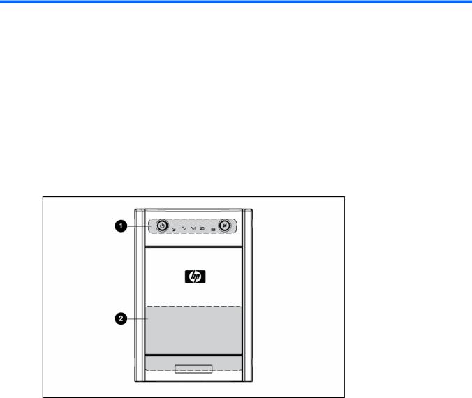
UPS front panel
Item |
Description |
|
|
1 |
Control buttons and LED display |
|
|
2 |
Battery compartment |
|
|
Component identification 6
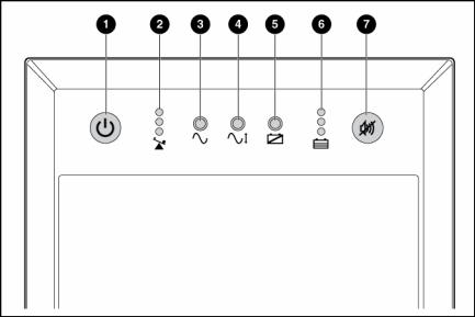
UPS front panel controls and LED indicators
Item |
Description |
Function |
|
|
|
1 |
Power On/Standby |
Turns the UPS power on and off, and places the UPS in Standby mode.1 |
|
button |
|
2 |
Output Load Level LED |
Shows approximately how much of the UPS power capacity is used to |
|
|
support the equipment connected to the output receptacles. |
|
|
Red—Maximum load |
|
|
Amber—Medium load |
|
|
Green—Light load |
|
|
|
3 |
Power LED |
Green—The UPS is on and supplying connected equipment with AC |
|
|
power. |
|
|
Flashing green—The UPS is operating from its internal batteries during a |
|
|
blackout or severe brownout. If the blackout or brownout is prolonged, |
|
|
save any open files and shut down the connected equipment. |
|
|
|
4 |
Voltage Correction LED |
Green—The UPS is automatically correcting high or low AC voltage on |
|
|
the utility line without the assistance of battery power. The UPS will emit a |
|
|
slight clicking noise. |
5 |
Battery Warning LED |
Amber—During a self-test, the UPS found that the batteries must be |
|
|
recharged. Charge the batteries and repeat the self-test ("Initiating a self- |
|
|
test" on page 19). |
|
|
|
Component identification 7
Item |
Description |
Function |
|
|
|
6 |
Battery Charge LED |
When the UPS is operating from utility power (the Power LED is green), |
|
|
the Battery Charge LED indicates the approximate charge state of the |
|
|
batteries: |
|
|
Red—The batteries are beginning to charge. |
|
|
Amber—The batteries are midway through charging. |
|
|
Green—The batteries are fully charged. |
|
|
When the UPS is operating on battery power during a blackout or severe |
|
|
brownout (the Power LED is flashing green), the Battery Charge LED |
|
|
indicates the approximate amount of remaining battery energy: |
|
|
Red—The batteries have a low level of energy. |
|
|
Amber—The batteries have a medium amount of energy. |
|
|
Green—The batteries have a high amount of energy. |
|
|
Periodically initiate a self-test ("Initiating a self-test" on page 19) to |
|
|
determine the energy level of the batteries before a blackout or brownout |
|
|
occurs. |
7 |
Mute/Test button |
Silences UPS alarms and initiates a self-test ("Initiating a self-test" on |
|
|
page 19). |
|
|
|
1  IMPORTANT: While in Standby mode, the UPS maintains the charge on the batteries, but no power is available at the output receptacles. The UPS remains in Standby mode until an alternate mode is selected or until utility power is removed.
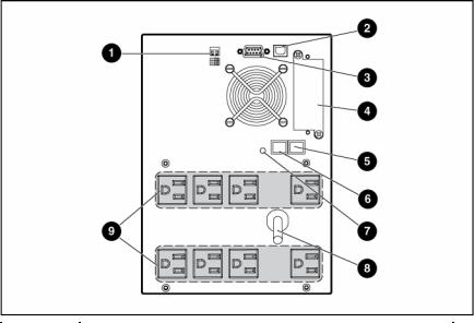
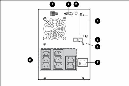
UPS T1000 NA/JPN/TWN rear panel
Item |
Description |
|
|
1 |
Voltage configuration DIP switches |
|
|
2 |
USB communications port |
|
|
3 |
Serial communications port |
|
|
4 |
Option slot |
|
|
5 |
Network Transient Protector IN jack |
|
|
Component identification 8
Item |
Description |
|
|
6 |
Network Transient Protector OUT jack |
|
|
7 |
Site Wiring Fault LED |
|
|
8 |
Input power cord with NEMA 5-15 plug |
|
|
9 |
Eight NEMA 5-15 output receptacles for surge and battery |
|
backup protection. |
|
|
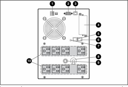
UPS T1500 NA/JPN/TWN rear panel
Item |
Description |
|
|
1 |
Voltage configuration DIP switches |
|
|
2 |
Serial communications port |
|
|
3 |
USB communications port |
|
|
4 |
Option slot |
|
|
5 |
Network Transient Protector IN jack |
|
|
6 |
Network Transient Protector OUT jack |
|
|
7 |
Site Wiring Fault LED |
|
|
8 |
Input power cord with NEMA 5-15 plug |
|
|
9 |
Input circuit breaker |
|
|
10 |
Eight NEMA 5-15 output receptacles for surge and battery |
|
backup protection. |
|
|
Component identification 9
UPS T1000 INTL rear panel
Item |
Description |
|
|
1 |
Voltage configuration DIP switches |
|
|
2 |
Serial communications port |
|
|
3 |
USB communications port |
|
|
4 |
Option slot |
|
|
5 |
Network Transient Protector IN jack |
|
|
6 |
Network Transient Protector OUT jack |
|
|
7 |
Input power receptacle (IEC-320-C14) for country-specific plug |
|
attachment |
8 |
Eight IEC-320-C13 output receptacles for surge and battery |
|
backup protection |
|
|
Component identification 10
UPS T1500 INTL rear panel
Item |
Description |
|
|
1 |
Voltage configuration DIP switches |
|
|
2 |
Serial communications port |
|
|
3 |
USB communications port |
|
|
4 |
Option slot |
|
|
5 |
Network Transient Protector IN jack |
|
|
6 |
Network Transient Protector OUT jack |
|
|
7 |
Input circuit breaker |
|
|
8 |
Input power receptacle (IEC-320-C14) for country-specific |
|
plug attachment |
9 |
Eight IEC-320-C13 output receptacles for surge and battery |
|
backup protection |
|
|
Component identification 11

Installation
In this section |
|
Precautions............................................................................................................................................ |
12 |
Electrical requirements ............................................................................................................................ |
12 |
Checking the battery recharge date.......................................................................................................... |
13 |
Connecting the batteries.......................................................................................................................... |
13 |
Selecting the UPS voltage configuration .................................................................................................... |
14 |
Connecting the host computer.................................................................................................................. |
15 |
Connecting the Network Transient Protectors ............................................................................................. |
16 |
Connecting the UPS to utility power.......................................................................................................... |
17 |
Connecting devices to the UPS................................................................................................................. |
17 |
Charging the UPS batteries...................................................................................................................... |
17 |
Powering up the UPS .............................................................................................................................. |
18 |
Precautions
Save these instructions. This document contains important safety instructions that should be followed during installation, operation, and maintenance of the UPS and batteries.
WARNING: A risk of personal injury from electric shock and hazardous energy levels exists. The installation of options and routine maintenance and service of this product must be performed by individuals who are knowledgeable about the procedures, precautions, and hazards associated with AC power products.
WARNING: To prevent personal injury from earth conductor leakage current:
•Do not operate the UPS while disconnected from the utility power source.
•Disconnect load devices before disconnecting the UPS from the utility power source.
WARNING: To prevent personal injury, prepare the area and observe all materials handling procedures when transporting the UPS. When fully assembled, the UPS weighs 20.3 kg (44.8 lb).
WARNING: To prevent personal injury, prepare the area and observe all materials handling procedures when transporting the UPS. When fully assembled, the UPS weighs 15.9 kg (35 lb).
Electrical requirements
WARNING: To prevent fire or electric shock, install the unit in a temperatureand humidity-controlled indoor environment, free of conductive contaminants.
Installation 12
Checking the battery recharge date
Before unpacking the UPS, check the date on the battery recharge date label that is affixed to the shipping carton.
IMPORTANT: Do not use the battery if the recharge date has passed. If the date on the battery recharge date label has passed without the battery being recharged, contact an HP authorized service representative for directions.
Connecting the batteries
WARNING: The unit contains sealed lead-acid battery modules. To prevent fire or chemical burns:
•Do not attempt to recharge batteries after removal from the unit.
•Do not disassemble, crush, or puncture the batteries.
•Do not short the external contacts of the batteries.
•Do not immerse the batteries in water.
•Do not expose to temperatures higher than 40°C (104°F).
WARNING: To prevent personal injury from hazardous energy:
•Remove watches, rings, or other metal objects.
•Use tools with insulated handles.
•Do not place tools or metal parts on top of batteries.
IMPORTANT: Before performing the following tasks, be sure that the unit is powered down and disconnected from the utility power source.
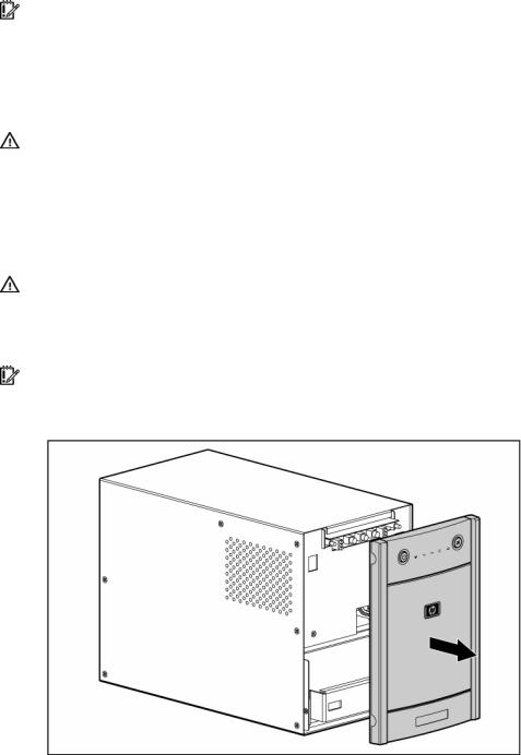
1.Remove the UPS front bezel.
Installation 13

2.Connect the negative (black) lead to the negative battery terminal.
NOTE: A small amount of arcing may occur when connecting the batteries. This is normal and does not damage the unit or present any safety concern.
3.Replace the UPS front bezel.
Selecting the UPS voltage configuration
Using a small tool, position the DIP switches according to the desired voltage configuration as identified on the rear panel of the UPS and in the following table.
NOTE: The DIP switches must be set before powering up the unit. The unit does not change operating modes while powered up.
NOTE: An asterisk (*) indicates the default setting.
|
Output voltage |
Input voltage range |
DIP switch 2 |
DIP switch 1 |
|
|
|
|
|
Installation 14
|
Output voltage |
Input voltage range |
DIP switch 2 |
DIP switch 1 |
|
|
|
|
|
|
|
T1000/1500 |
100 V* |
90–106 V |
Down |
Up |
|
NA/JPN/TWN |
(JPN/TWN) |
|
|
|
|
|
|
|
|
|
|
|
110 V |
99–116 V |
Up |
Down |
|
|
|
|
|
|
|
|
120 |
V* (NA) |
108–127 V |
Down |
Down |
|
|
|
|
|
|
|
120 |
V |
108-127 V |
Up |
Up |
|
|
|
|
|
|
T1000/1500 INTL |
220 V |
198–233 V |
Down |
Up |
|
|
|
|
|
|
|
|
230 |
V* (INTL) |
207–243 V |
Up |
Down |
|
|
|
|
|
|
|
230 |
V |
207-243 V |
Down |
Down |
|
|
|
|
|
|
|
240 V |
216–254 V |
Up |
Up |
|
|
|
|
|
|
|
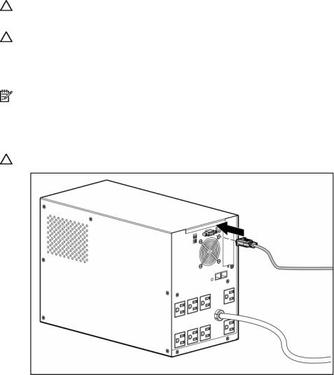
Connecting the host computer
CAUTION: Use only the computer interface cable supplied with the UPS to connect the communications port to the host computer.
CAUTION: Using a USB to serial converter cable will damage the UPS.
Connect the UPS to a host computer using either the USB cable or the DB9 serial cable included with the UPS. Install HP Power Manager software 4.1 or later on the host computer. See the HP website (http://www.hp.com/go/rackandpower) to download the latest version of HP Power Manager.
NOTE: To install and configure the software, see the software user guide. The software user guide is available for download from the HP website (http://www.hp.com/go/rackandpower).
Connecting the serial communications port
CAUTION: Using a USB to serial converter cable will damage the UPS.
Installation 15
Loading...