


T770
Table of contents
 Loading...
DESIGNJET T770 & T1200 printer series
Service manual

© 2010 Hewlett-Packard Development
Company, L.P.
1st edition
Legal notices
This document contains proprietary
information that is protected by copyright.
All rights are reserved. No part of this
document may be photocopied, reproduced,
or translated to another language without
the prior written consent of Hewlett-Packard
Company.

Table of contents
1 Troubleshooting ................................................................................................................ 1
Using the Front Panel ................................................................................................................ 2
General troubleshooting ........................................................................................................... 3
Paper-handling troubleshooting .................................................................................................. 6
Print-quality troubleshooting ....................................................................................................... 6
Ink-supplies troubleshooting ..................................................................................................... 32
Connectivity troubleshooting .................................................................................................... 48
2 System Error Codes ......................................................................................................... 53
Introduction ........................................................................................................................... 54
Printer logs ............................................................................................................................ 54
What to do if the Front Panel is blank ....................................................................................... 55
Continuable and Non-Continuable Error Codes ......................................................................... 56
System Error Code Brief Descriptions ........................................................................................ 56
System Error Codes—Full Descriptions ...................................................................................... 58
Appendix A: How to troubleshoot SE 79:04 .............................................................................. 77
Appendix B: Updating firmware in diagnostics boot mode .......................................................... 89
Appendix C: Obtaining the printer log and the diagnostics package ............................................ 90
Appendix D: How to check the display list memory for an HP-GL/2 job ........................................ 92
3 Diagnostics Menu ........................................................................................................... 94
Introduction ........................................................................................................................... 95
Diagnostic Tests and Utilities .................................................................................................... 96
4 Service Menu ................................................................................................................ 12 8
Introduction ......................................................................................................................... 129
Service Utilities .................................................................................................................... 129
Service Calibrations ............................................................................................................. 147
5 Parts and Diagrams ...................................................................................................... 159
Introduction ......................................................................................................................... 160
Printer Support ..................................................................................................................... 161
Center Covers (Front) ............................................................................................................ 162
Roll Covers .......................................................................................................................... 163
Center Covers (Rear) ............................................................................................................ 164
Right Cover ......................................................................................................................... 165
ENWW iii

Left Cover ........................................................................................................................... 166
Right Hand Assemblies ......................................................................................................... 167
Left Hand Assemblies ............................................................................................................ 168
Carriage Assembly ............................................................................................................... 169
Scan-Axis Assemblies ........................................................................................................... 170
Paper Path Assemblies (Front) ................................................................................................ 171
Paper Path Assemblies (Rear) ................................................................................................. 172
Roll Supports ....................................................................................................................... 173
Tools 1 ............................................................................................................................... 174
Tools 2 ............................................................................................................................... 175
Miscellaneous Parts .............................................................................................................. 176
6 Removal and Installation .............................................................................................. 177
Introduction ......................................................................................................................... 180
Customer Self Repair parts .................................................................................................... 182
Service Calibration Guide to Removal and Installation .............................................................. 184
Belt Assembly ...................................................................................................................... 187
Bin Assembly ....................................................................................................................... 188
Bi-stable Springs (T1200 only) ............................................................................................... 191
Bumpers, Left and Right ......................................................................................................... 197
Cable Harness ..................................................................................................................... 200
Carriage and Cutter Assembly ............................................................................................... 208
Carriage Bushing, Rear ........................................................................................................ 217
Carriage Cover and Carriage Latch ....................................................................................... 219
Carriage Rail Oiler .............................................................................................................. 224
Carriage PCA ...................................................................................................................... 226
Cleanout ............................................................................................................................. 231
Converger ........................................................................................................................... 233
Cover, Front ........................................................................................................................ 235
Cover, Left .......................................................................................................................... 236
Cover, Rear ......................................................................................................................... 240
Cover, Right ........................................................................................................................ 241
Cover, Top .......................................................................................................................... 244
Cutter Assembly ................................................................................................................... 247
Drop Detector ...................................................................................................................... 251
EE Box ................................................................................................................................ 253
Electronics Module Main PCA and PSU .................................................................................. 256
Encoder Disk and Encoder Sensor .......................................................................................... 260
Encoder Strip ....................................................................................................................... 262
Encoder Strip, spring and attachment nut ................................................................................ 263
Formatter ............................................................................................................................ 266
Freewheel Assembly ............................................................................................................. 267
Front Panel .......................................................................................................................... 270
Front Trim, Left ..................................................................................................................... 273
Front Trim, Right ................................................................................................................... 275
Full Bleed Foam ................................................................................................................... 277
Hard Disk Drive ................................................................................................................... 278
iv ENWW

Ink Cartridge Door, Left ........................................................................................................ 279
Ink Cartridge Door, Right ...................................................................................................... 281
Ink Supply Station, Left .......................................................................................................... 283
Ink Supply Tubes .................................................................................................................. 287
Ink Supply Tubes Support Rail ................................................................................................ 294
Line Sensor .......................................................................................................................... 296
Media Advance Drive .......................................................................................................... 302
Media Lever ........................................................................................................................ 309
Media Lever Position Sensor .................................................................................................. 311
Media Output Assembly ....................................................................................................... 313
Out-of-paper Sensor ............................................................................................................. 315
Panel, Left ........................................................................................................................... 318
Pen to Paper Space (PPS) Solenoid ......................................................................................... 320
Pinch Arm Assembly (T1200 only) .......................................................................................... 322
Pinchwheel Assembly ........................................................................................................... 325
Print Zone Overdrive ............................................................................................................ 333
PSU .................................................................................................................................... 337
Real-time Clock Battery ......................................................................................................... 339
Roll Cover Bumpers, Lower .................................................................................................... 340
Roll Cover Bumpers, Upper ................................................................................................... 343
Roll Cover, Lower (T1200 only) ............................................................................................. 346
Roll Cover, Upper ................................................................................................................ 350
Roll Guide, Left .................................................................................................................... 352
Roll Guide, Right .................................................................................................................. 353
Roll Support, Lower Left (T1200 only) ..................................................................................... 354
Roll Support, Lower Right (T1200 only) ................................................................................... 355
Roll Support Sensor, Lower Left (T1200 only) ........................................................................... 357
Roll Support Sensor, Upper Left (T1200 only) .......................................................................... 358
Roll Support, Upper Left ........................................................................................................ 359
Roll Support, Upper Right ...................................................................................................... 361
Scan-axis Motor ................................................................................................................... 363
Service Station ..................................................................................................................... 367
Single-sheet Sensor ............................................................................................................... 371
Spindle ............................................................................................................................... 373
Spittoon, Left ....................................................................................................................... 374
Starwheel Assembly ............................................................................................................. 375
Starwheel Lifter, Left .............................................................................................................. 377
Starwheel Lifter, Right ........................................................................................................... 379
Starwheel Motor .................................................................................................................. 382
Trailing Cable ..................................................................................................................... 384
Wall Spacers ...................................................................................................................... 391
Window ............................................................................................................................. 394
Window Position Sensor ....................................................................................................... 398
7 Preventive Maintenance ............................................................................................... 400
Preventive Maintenance ........................................................................................................ 401
Preventive Maintenance Kits .................................................................................................. 406
ENWW v

Appendix A Front-panel menu maps ............................................................................... 408
HP Designjet T770 ............................................................................................................... 409
HP Designjet T770 HD .......................................................................................................... 410
HP Designjet T1200 ............................................................................................................. 411
Appendix B CSR installation fliers .................................................................................... 412
Cutter assembly ................................................................................................................... 413
Freewheel assembly ............................................................................................................. 415
Freewheel assembly (screwdriver) .......................................................................................... 417
Left side panel (T1200) ......................................................................................................... 419
Pinch arm assembly .............................................................................................................. 421
Pinch arm assembly (screwdriver) ........................................................................................... 423
Roll cover upper bumpers ...................................................................................................... 425
Roll cover upper bumpers (screwdriver) ................................................................................... 427
vi ENWW

1 Troubleshooting
●
Using the Front Panel
●
General troubleshooting
●
Paper-handling troubleshooting
●
Print-quality troubleshooting
●
Ink-supplies troubleshooting
●
Connectivity troubleshooting
ENWW 1
Troubleshooting
Using the Front Panel
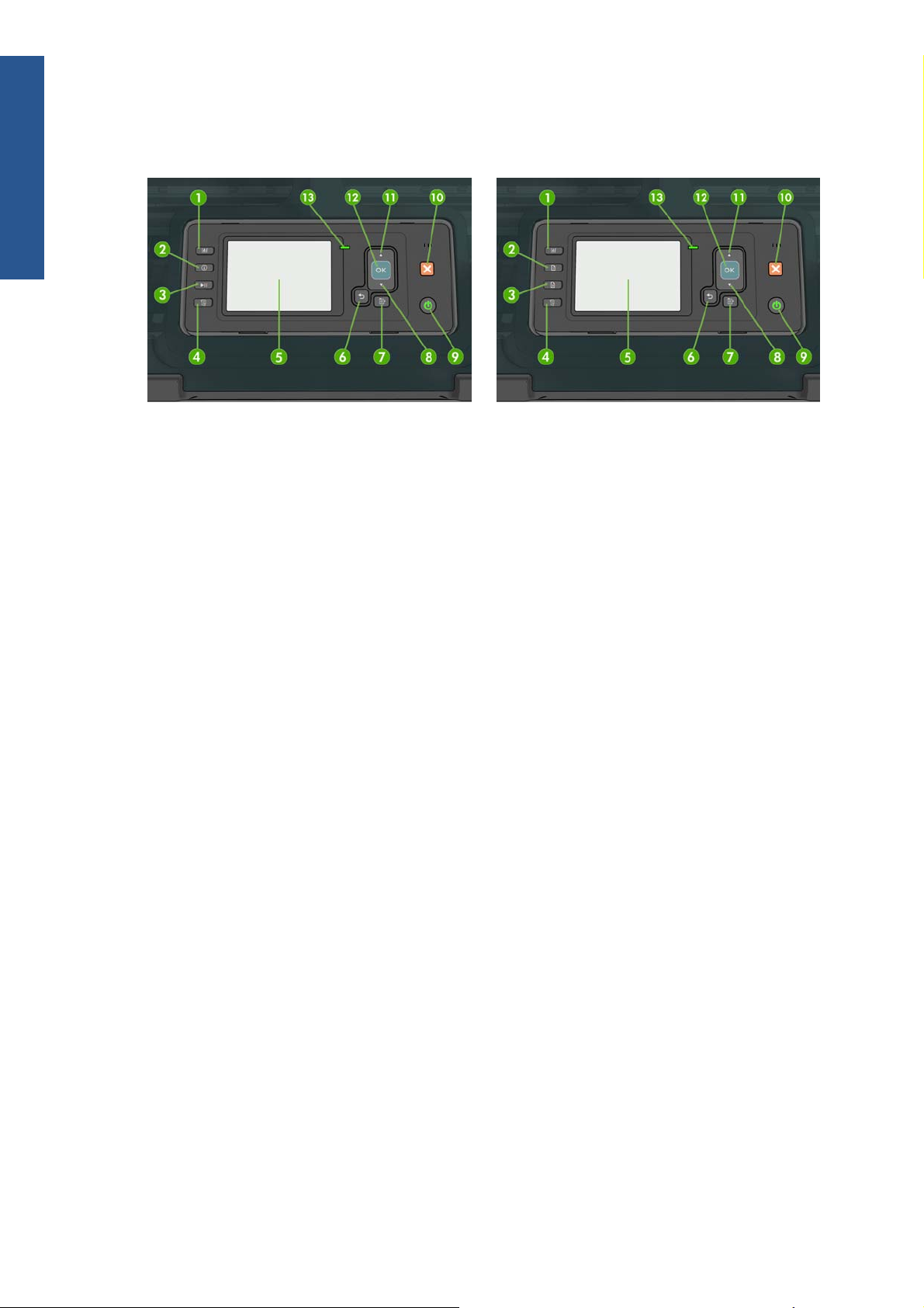
HP Designjet T1200 series HP Designjet T770 series
The front panel has the following components, starting with the four direct-access keys:
1. View ink levels key.
2. View information key. By pressing this key repeatedly, you can see information about all loaded
papers (roll 1, roll 2, sheet) and about the printer's connection to the computer.
3. Pause printing key (T1200 series) pauses printing after finishing the current page. Press the key
again to restart printing. This can be useful, for instance, when you want to change or load a roll.
Unload paper key (T770 series) unloads the currently-loaded paper (roll or sheet).
4. Form feed and cut key.
5. Front-panel display - Displays errors, warnings and information on using your printer.
6. Back key - To go to the previous step in a procedure or interaction. To go to the upper level, or
leave the option in the menu, or when given an option.
7. Menu key - Press to return to the main menu of the front-panel display. If you are already on the
main menu it will display the status screen.
8. Down key - To go down in a menu or option, or to decrease a value, for example when
configuring the front-panel display contrast or the IP address.
9. Power key - To turn the printer off or on, it also has a light to indicate the printer's status. If the
power key light is off the printer is off. If the power key light is blinking green, the printer is
starting up. If the power key light is green on, the printer is on. If the power key light is amber on,
the printer is in standby. If the power key light is blinking amber, the printer needs attention.
10. Cancel key - To abort a procedure or interaction.
11. Up key - To go up in a menu or option, or to increase a value, for example when configuring the
front-panel display contrast or the IP address.
2 Chapter 1 Troubleshooting ENWW
Troubleshooting

12. OK key - To confirm an action while in a procedure or interaction. To enter in a submenu in the
menu. To select a value when given an option. If the status screen is displayed, this key takes you
to the main menu.
13. Status light - Indicates the printer's status. If the Status light is solid green, the printer is ready. If it
is flashing green, the printer is busy. If it is solid amber, there is a system error. If it is flashing
amber, the printer needs attention.
Table 1-1 Service Key Combinations
Label Description
Diagnostic mode With the printer off, press and hold the Up and OK keys.
While holding the Up and OK keys down, press the Power
key to turn on the printer. Wait until the HP logo appears in
the front-panel display, then release all three keys.
Service menu (service engineers only) From the main menu, press and hold the Up and Cancel
keys.
Service menu (for users) From the main menu, press and hold the Down and Cancel
keys.
For a full list of front-panel options and how to reach them, see Front-panel menu maps on page 408.
General troubleshooting
This chapter will guide you through the relevant steps to take when troubleshooting the printer.
Troubleshooting system error codes
System Error Codes on page 53 contains a list of system error codes and their respective descriptions
and recommended corrective actions. Try only one recommended action at a time and check whether
the error code has disappeared.
If you have an error code which is not documented in this Service Manual or you have an error which
you cannot resolve, then report the error to the HP Response Center or the nearest HP Support Office.
When reporting the error, have the following information ready:
●
Model and Serial Number of the printer.
●
Which firmware revision the printer is using (See Note below). Check firmware in Utilities /
Statistics / Code rev.
●
The complete error number (See Note below).
●
The Service Configuration Print.
●
The Current configuration sheet.
●
Which software application the customer is using (name, version, etc.).
NOTE: When reporting the System Error Code, make sure that you supply the full Error Code and the
firmware version. Without this information, HP Support Personnel cannot help you.
ENWW
General troubleshooting
3
Troubleshooting

Performing a service test on a failed assembly
If possible, always perform a Service Test on the component/assembly that you are about to replace,
just to make sure that is the component/assembly that has failed.
NOTE: If the test on that component/assembly passes, you should not replace it.
For information on the Service Tests and how to use them see
Diagnostics Menu on page 94.
Performing the necessary service calibrations
Is the printer calibrated correctly after replacing a component? For information on the Service
Calibrations and how to use them see
Service Menu on page 128.
NOTE: Remember that certain Calibrations are required even if an Assembly has been disassembled
to gain access to another Assembly or Component.
Solving print-quality problems
Whenever a print-quality problem appears, it is advisable to print the Diagnostic Print to help diagnose
the problem. The Diagnostic Print will help you differentiate between possible printhead errors and
other problems such as incorrect front-panel selection, driver or RIP configuration or mechanical
problems.
The Front Panel is blank
See What to do if the Front Panel is blank on page 55.
The printer does not power on
See What to do if the Front Panel is blank on page 55.
The printer continuously rejects printheads
1. Clean the flex contacts on the Printhead and in the Carriage Assembly using the Carriage
Interconnect Wiper and try again.
2. If all the Printheads are rejected (the status message on the Front Panel does not show "OK" for
all the Printheads) then perform the Electronic Module Test. See
Electronics Module Test
on page 106.
Cover sensors are not working
1. Perform the Sensors Test. See Sensors Test on page 113.
2. Check that the cable for the faulty sensor is not damaged and is connected correctly.
3. Replace the faulty Sensor.
4 Chapter 1 Troubleshooting ENWW
Troubleshooting

The line sensor has problems detecting paper
1. Check the type of paper that is being used since the Line sensor may have problems detecting
transparent paper or some types of Non-HP paper. Try loading white HP paper in to the printer
and check that the Line sensor detects it.
2. The Line Sensor is not calibrated correctly. Perform the Line Sensor Calibration. See
Line Sensor
Calibration on page 155.
3. The Line Sensor is damaged or faulty. Replace the Line Sensor. See
Line Sensor on page 296.
Troubleshooting paper jams and printhead crashes
The failure modes "paper jam" and "head crash" are grouped together because in many cases a
paper jam causes the paper to lift up into the Carriage path and cause a Printhead crash, thus causing
many paper jam failures to be reported as head crashes.
1. Did the paper jam occur when loading paper?
●
If the client has had paper jams, it is common for pieces of paper to get stuck in the paper
path. Clear the paper path.
NOTE: When clearing a paper jam, sometimes paper is stuck in the paper path. To clear this,
you must lift the Media Lever and insert thicker paper into the paper path to push out the paper
that is still stuck there.
2. Is the customer using non-HP paper?
●
The use of non-HP paper can easily be the cause of paper jams and head crashes (especially
head crashes because HP paper is specially formulated to avoid cockle, one of the primary
causes of head crashes). If the paper is not HP approved, advise the customer to use HP
paper and check to see whether the problem is now solved.
Banding at variable extreme environmental conditions
Since the Accuracy Calibration has been done at normal environmental conditions, printing in extreme
environmental conditions will cause banding because the advance of the Media Advance Roller does
not correspond to the same conditions that the calibration was done in. To solve the problem, try the
following:
Perform the Accuracy Calibration in the new environmental conditions (Refer to the User’s Guide).
Worm marks on HP Coated paper with light area fills
Light bands (S-shaped) in Paper axis direction where light area fills are printed, causing unacceptable
Image Quality defect.
●
Print the Service Configuration Print and check whether the humidity level is very low (below 30%).
Increasing humidity may help in reducing the severity of the problem.
NOTE: The paper is causing the problem and not the printer. Do not attempt to try to replace printer
parts to solve this problem.
ENWW
General troubleshooting
5
Troubleshooting

The basket was damaged during printer setup
1. There are three plastic parts that could break during printer installation and need replacing.
2. Check the parts table and graphics in Parts and Diagrams to identify what service parts you must
order. See
Printer Support on page 161.
3. Replace the component. See
Bin Assembly on page 188.
Paper-handling troubleshooting
Roll paper The Front Panel indicates that paper is misaligned or incorrectly positioned
●
The roll may be loaded the wrong way. The paper should load over the roll toward you.
●
Check that the paper is correctly loaded onto the spindle.
●
The paper may be loaded at an angle. The right-hand edge must be aligned with the blue line on the
Print Platen.
●
Check that the Right Roll Support is properly attached and screwed to the printer.
The Rewinder, located on the Right Roll Support, should maintain proper back tension. If the Right Roll
Support is misaligned or not properly attached to the printer, the Rewinder will not function properly.
To further diagnose problems with the Rewinder, see
Rewinder Test on page 114.
Sheet paper
●
The sheet must be loaded with the right-hand edge against the white line on the upper roll cover.
●
The paper may be crumpled or warped or may have irregular edges.
●
If hand-cut paper is used, the edges may not form a right-angle or they may be rough. If possible,
hand-cut paper should not be used. Only purchased sheet paper should be used in the printer.
●
If you have problems with paper jams, check that the Overdrive is not obstructed by bits of paper or
using the Turn Drive Roller Service Utility. See
Turn Drive Roller on page 130.
Check that the Right Roll Support is properly attached and screwed to the printer.
The Rewinder, located on the Right Roll Support, should maintain proper back tension. If the Right Roll
Support is misaligned or not properly attached to the printer, the Rewinder will not function properly.
To further diagnose problems with the Rewinder, See
Rewinder Test on page 114.
Print-quality troubleshooting
Print-quality troubleshooting actions
NOTE: For some print-quality problems, a Call Agent can try to troubleshoot the printer by requesting
the Customer to perform certain actions. Using this process, most problems can resolved without the
need of an on-site visit.
Use the Print Quality Troubleshooting Wizard to help customers with their print quality or color
problems. For information about how to use the Print Quality Troubleshooting Wizard, see
Print Quality
Troubleshooting Wizard on page 30.
6 Chapter 1 Troubleshooting ENWW
Troubleshooting

When faced with a Print Quality problem, perform the following actions in order to resolve the
problem:
1. Printer Configuration:
●
Check that the paper type loaded corresponds to the paper type selected in the front panel
and in the software. You can check the paper type selected by pressing the View
information key on the Front Panel.
●
Make sure that the correct Print Quality settings are used for different types of print content.
See
Print-quality troubleshooting actions on page 6 for further information.
●
Dry time should be set to “Optimal”.
2. Perform Printhead recovery (Main Menu/Image Quality Maintenance/Clean Printheads).
3. Paper:
●
Select the correct paper type through the front panel when loading it.
●
Make sure that HP or HP-approved paper is being used.
4. Perform the Printhead Alignment (Main Menu/Image Quality Maintenance/Align Printheads),
using the same paper type with which you were experiencing unacceptable image quality, if
feasible (some paper types are not suitable for Printhead Alignment).
5. Check whether the latest version of the firmware is installed. If not, install the latest firmware
revision.
The Service Image Quality Diagnostic Print
What is the Service Image Quality Diagnostic Print?
The printer contains an internal Image Quality Test which helps you to diagnose the possible source of
any image quality defects. The Service IQ Diagnostic Print is available in the following options:
1. Image Quality Service Best Plot. This plot helps you to diagnose in more detail the possible source
of any image quality defects. It is accessible through the Service Utility Menu.
The Image Quality Service Best Plot uses the Best Print Mode and is divided in to three parts as
follows:
●
Diagnostic Part 1: Printhead Reliability Test. The purpose of this test is to identify which
Printhead is faulty.
●
Diagnostic Part 2: Printhead Alignment Test. This test is designed to check any color-to-color
and bi-directional misalignment the printer may have.
●
Diagnostic Part 3: Printheads and Paper Advance test. This test is designed to check whether
the Printheads and the Media Advance Mechanism are working correctly.
2. Image Quality Service Normal Plot. This plot is the same as the Image Quality Service Best Plot but
uses the Normal Print Mode.
3. Advanced Diagnostic Plot. These tests provide more information of the IQ defects that we could
find in the Image Quality Service plot. For more information, see
The Advanced Diagnostic Prints
on page 12.
ENWW
Print-quality troubleshooting
7
Troubleshooting
Considerations for Printing the Diagnostic Print
1. The IQ Diagnostic Print prints in A3 and B sizes so you must have paper loaded (roll or sheet) that
is this size or larger.
2. Use the same type of paper that the customer was using when they found the image quality
problem.
3. If the customer is using non-HP paper and after the Image Quality Test you still have the same
image quality problems, change to genuine HP paper and repeat the Image Quality Test.
If you do see problems with the Image Quality Test, continue with the Advanced Diagnostic
procedures which will help you diagnose the problem.
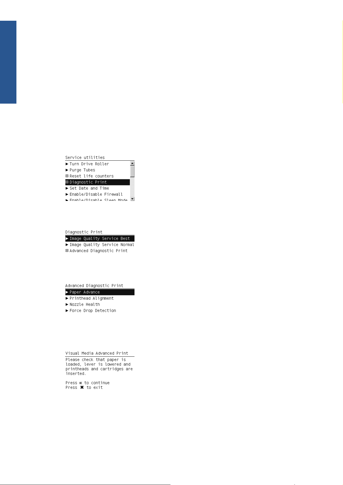
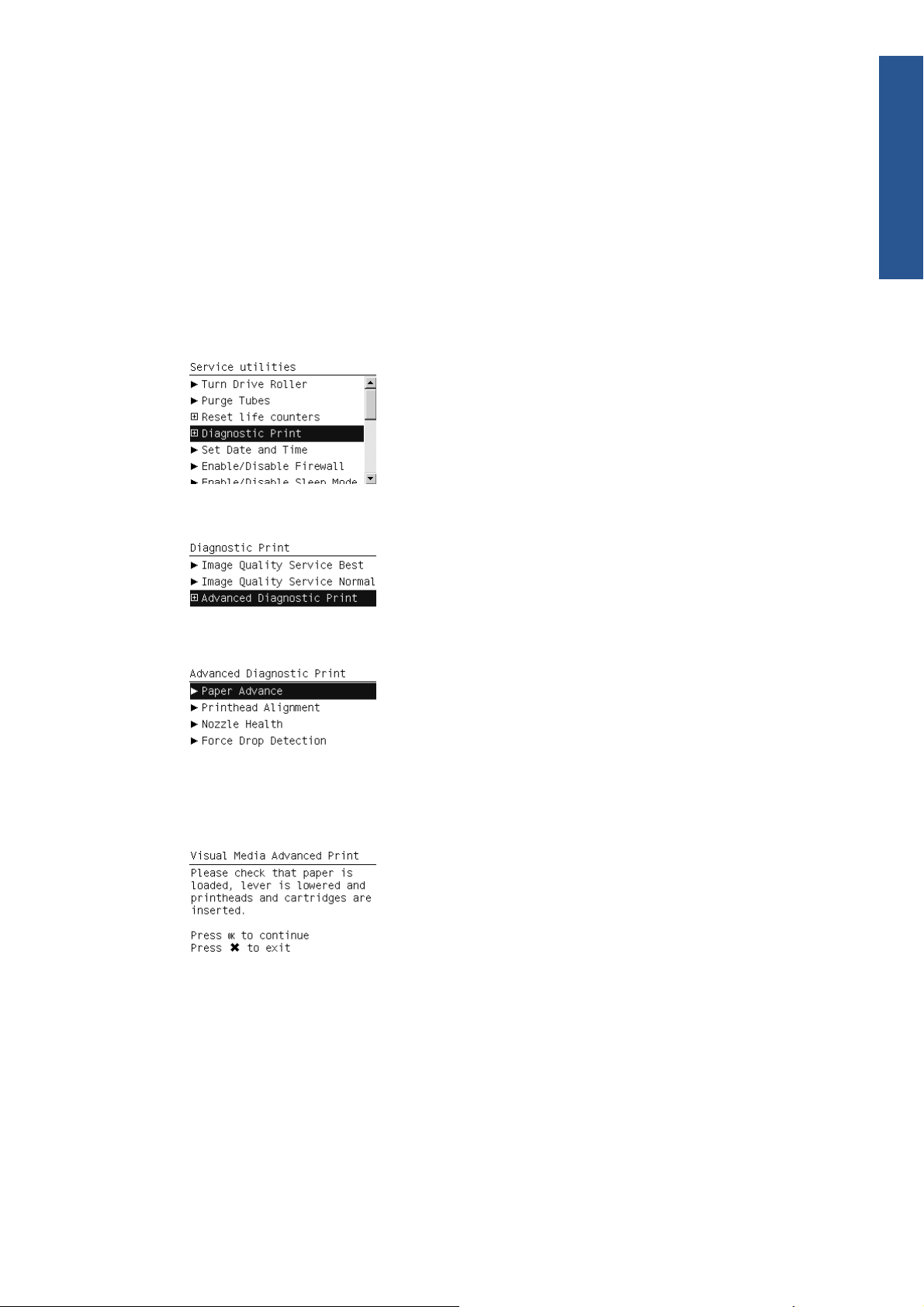
Printing the Diagnostic Print
1. In the Service Utilities submenu, scroll to “Diagnostic Print” and press OK.
2. You will be given three options. Use the Arrow keys to make the selection and press the OK key
to start printing the required Diagnostic Print or to enter the Advanced Diagnostics menu.
3. If you selected Advanced Diagnostics Print in the previous step, use the Arrow keys to make
the required selection,and press the Enter key to start printing.
4. Make sure paper is loaded, the Media Lever is lowered and that the Ink System is correctly
installed. Press the OK key to print the Diagnostic Print or press Cancel to exit without printing the
Diagnostic Print.
5. The selected Diagnostic Print will now be printed.
Reading the Diagnostic Print results
Diagnostic Part 1: Printhead Reliability
8 Chapter 1 Troubleshooting ENWW
Troubleshooting
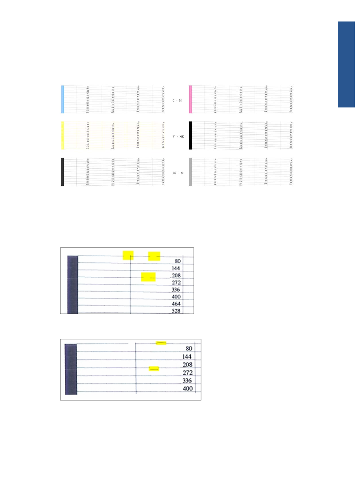
The Nozzle Print Test test is designed to check that the Printhead nozzles print correctly.
The nozzles check (top of the plot) is printed in a one-pass full swath mode. The diagnostics test prints
out every single nozzle of each Printhead without applying an error hiding or alignment algorithm.
For each Printhead, you can see both the adjacent and the consecutive nozzles.
If any nozzles are not printing correctly they will be shown on the right of each Printhead Nozzle test.
There is a series of numbered stepped diagonal lines. If one or more of the nozzles are clogged,
malfunctioning or mis-positioned, you will see that the stepped lines are broken or misdirected in one or
more places.
Below, the stepped lines highlighted in yellow are broken. When the line is completely broken, this
means the nozzle is out.
Below, the stepped lines highlighted in yellow are misdirected. When the line is misdirected, this means
the nozzle is malfunctioning or out of position.
On the left of each Printhead Nozzle test, there is a series of horizontal straight lines. If one or more
nozzles are misdirected there will be unequal spaces between the corresponding lines.
Corrective action
If the printer has nozzle defects, you can still get perfect print quality results. The printer can
automatically compensate for nozzle defects, so there is no need to replace the Printhead.
ENWW
Print-quality troubleshooting
9
Troubleshooting
The method of improving Nozzle Defects is to:
1. Recover the Printheads, using the Front Panel Main Menu/Image Quality Maintenance/Clean
Printheads option.
2. Reprint the Printhead Nozzles Test Plot to check that the defective nozzles have been corrected.
3. If the problem continues, replace the defective Printhead.
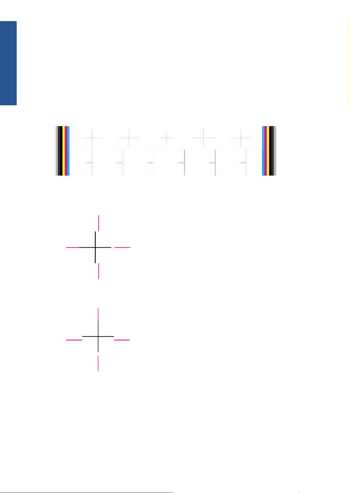
Diagnostic Part 2: Printhead Alignment
This test is designed to check any color-to-color and bi-directional misalignment the printer may have.
1. If the printer is experiencing horizontal misalignment problems, the Alignment Test will show
something like this:
2. If the printer is experiencing vertical misalignment problems, the Alignment Test will show
something like this:
10 Chapter 1 Troubleshooting ENWW
Troubleshooting

3. If the printer is experiencing bi-directional misalignment problems, the Alignment Test will show
something like this:
Corrective action
Perform the Printhead Alignment (Main Menu/Image Quality Maintenance/Align Printheads), using the
same paper type with which you were experiencing unacceptable image quality, if feasible (some
paper types are not suitable for Printhead Alignment).
Diagnostic Part 3: Printheads & Paper Advance
This test is designed to check whether the Printheads and the Paper Advance Mechanism are working
correctly. This part of the Image Quality Test should not be used to check for color consistency or
accuracy.
Banding
If the printer is experiencing a banding problem, you will see repetitive horizontal bands within the
printed image.
●
Darker horizontal bands or lines repeated along the vertical band (from top to bottom at the same
distance).
●
Whiter horizontal bands or lines along the vertical band (from top to bottom at the same distance).
The plot is printed in Best or Normal mode (according to the menu option selected) with Error Hiding
ON. The top band has 100% ink density patches while the bottom band has 50% ink density patches.
ENWW
Print-quality troubleshooting
11
Troubleshooting

Troubleshooting Banding Problems
If banding does not occur in all the colors, then it is more than likely a Printhead problem. In this
case, try the following:
1. Check that the appropriate print quality settings are being used (refer to the User’s Guide for more
information).
2. Recover the printheads using the option through the Front Panel (Main Menu/Image Quality
Maintenance/Clean Printheads). Reprint the Diagnostic Print or the print file and if the problem
persists, replace the faulty Printhead.
If banding does occur in all the colors, then it is more than likely a Paper Advance problem:
●
If the bands are light, it means that the paper has advanced too much.
●
If the bands are dark, it means that the paper hasn’t advanced enough.
●
In high quality modes, graininess in all colors can indicate problems either with alignment or
Paper Advance.
Corrective action
In order to solve problems that result in banding, try the following
1. Check that the appropriate print quality settings are being used (refer to the User’s Guide for more
information).
2. Check that the loaded paper is the same type as selected in the printer. You can check the paper
type selected through the Front Panel (Main Menu/Paper menu/View loaded paper).
3. If the customer is using low-quality paper, try recommending better-quality paper (preferably HP
paper). Printer performance can only be guaranteed by using recommended papers.
4. Perform Paper Advance Calibration using the same type of paper that will be used for the final
print (Main Menu/Image Quality Maintenance/Paper Advance Calibration/Calibrate Paper
Advance).
If there is white point banding in only one color band and the problem cannot be fixed using the
Printhead recoveries, in some cases using the Force Drop Detection option can fix this issue.
No Printing Defects Found in the Diagnostic Print
If all the test patterns from the Diagnostic Print are correct and you still experience Image Quality
problems, you can use the following procedures to resolve the problem.
●
Reading the Advanced Diagnostic Print Results
●
Printhead Alignment
●
Nozzle Health
●
Force Drop Detection
The Advanced Diagnostic Prints
What are the Advanced Diagnostic Prints?
These tests provide more information about the IQ defects found in the Image Quality Service plot.
12 Chapter 1 Troubleshooting ENWW
Troubleshooting
The Advanced Diagnostic Print is divided into the following parts:
●
Visual Media Advanced Diagnostic. Used to check advance reliability.
●
Printhead Alignment Diagnostic. Used to check pen alignment reliability.
●
Visual Nozzle health Diagnostic. Used to check nozzle health reliability.
●
Force Drop Detection. Used to reset the nozzle health historic database and force new drop
detection.
Printing the Advanced Diagnostics Print
1. In the Service Utilities submenu, scroll to “Diagnostic Print” and press OK.
2. You will be given three options. Use the Arrow keys to select Advanced Diagnostic Print.
3. Use the Arrow keys to select the option you want, and press the OK key to start printing.
4. Make sure paper is loaded, the Media Lever is lowered and that the Ink System is correctly
installed. Press the OK key to print the Diagnostic Print or press Cancel to exit without printing the
Diagnostic Print.
5. The selected Advanced Diagnostic Print will now be printed and, if necessary, automatically
scanned.
Reading the Advanced Diagnostic Print results
Paper Advance
This plot helps you to visually check any alignment problems of the printer. You use it to precisely
measure the paper advance error with a one dot row accuracy, and to check the stability of the paper
advance.
ENWW
Print-quality troubleshooting
13
Troubleshooting
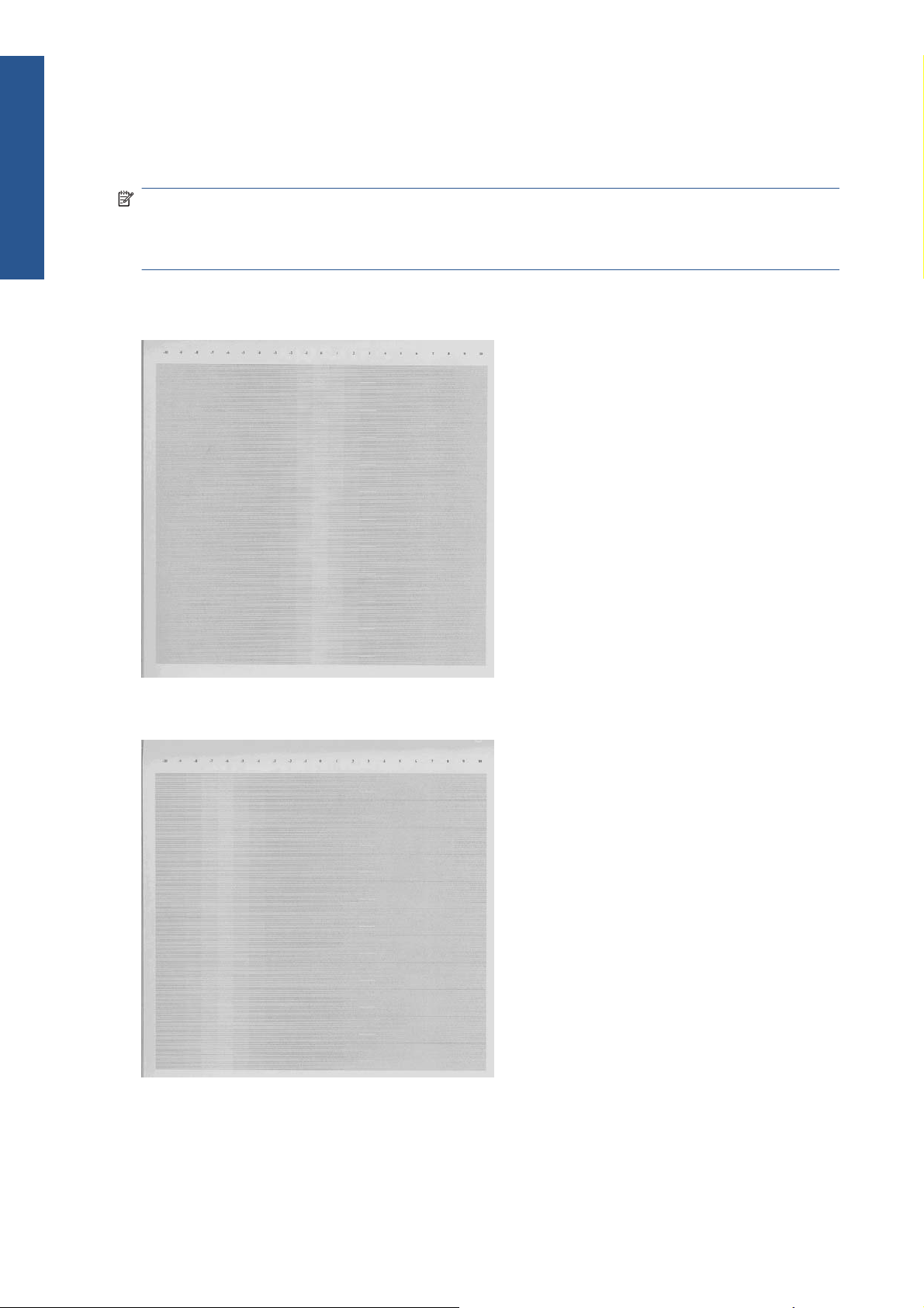
The whitest vertical line should be positioned in the 0 offset column with minor variations between +2
and -2 columns. If the offset is not positioned on the 0 column or between +2 and -2 columns and the
whitest vertical varies greatly, the printer requires Paper Advance Calibration (Main Menu/Image
Quality Maintenance/Paper Advance Calibration/Calibrate Paper Advance).
NOTE: It is very important to check that the loaded paper is the same paper type as selected in the
front panel. You can check the paper type selected through the Front Panel (Main Menu/Paper menu/
View loaded paper). The wrong type of paper selected will produce an offset error in the Paper
Advance.
The following plot shows correct paper advance, there is a straight white line positioned close to the 0
column for the majority of the points.
The following plot shows a bad paper advance, there is a straight white line positioned close to the -6
column, instead of the 0 column for the majority of the points.
14 Chapter 1 Troubleshooting ENWW
Troubleshooting

Corrective action
To fix Paper Advance problems, try the following:
1. Check the Paper Advance Calibration Status. This can be done by going to Main Menu/Paper/
View Loaded Paper. At the bottom, the Front Panel displays the Paper Advance Calibration status.
There are three status messages:
●
DEFAULT. The paper loaded is recognized as HP paper, which is already optimized and
calibrated for the printer. Do not calibrate the Paper Advance for this paper.
●
RECOMMENDED. The paper loaded is not recognized as HP paper, and Paper Advance
values have not been customized for this paper type. In this case, calibrate the Paper
Advance from the user menu.
●
OK. This indicates that the paper loaded has been calibrated before. If the printer continues
to have banding and graininess problems, calibrate the Paper Advance from the user menu.
NOTE: Whenever the printer's firmware is upgraded, the paper advance calibration values
will be reset to factory default.
2. To calibrate the Paper Advance from the user menu, go to Main Menu/Image Quality
Maintenance/Paper Advance Calibration/Calibrate Paper Advance.
NOTE: It is very important to check that the loaded paper is the same paper type as selected in
the front panel. You can check the paper type selected through the Front Panel (Main Menu/Paper
menu/View loaded paper). The wrong type of paper selected will produce an offset error in the
Paper Advance.
NOTE: Some paper types are not suitable for Paper Advance Calibration. Do not use colored
papers or transparent materials such as translucent bond, clear film, matte film, tracing paper, or
vellum.
Paper Advance calibration from the user menu will only calibrate the Paper Advance for the paper
type loaded in the printer at that moment.
3. If Calibrate Paper Advance has mostly solved the problem, try Adjust Paper Advance to fine tune
the Paper Advance (Main Menu/Image Quality Maintenance/Paper Advance Calibration/
Adjust Paper Advance).
Select the percentage of change from -100% to 100%. To correct light banding, decrease the
percentage. To correct dark banding, increase the percentage.
4. The Paper Advance calibration from the service menu will calibrate the Paper Advance for all
paper types. This action is recommended when:
●
The Paper Advance calibration from the user menu does not solve the problem.
●
The Paper Advance problems affect all paper types.
The procedure for Paper Advance Calibration from the service menu is documented in Chapter 5,
Service Calibrations. See
Paper Advance Calibration on page 148.
Printhead Alignment
NOTE: To ensure you obtain meaningful results, use the same type of paper that the customer was
using when they encountered the image quality problem.
ENWW
Print-quality troubleshooting
15
Troubleshooting
This plot helps you to visually check any alignment problems of the printer. You use it to precisely
measure the alignment error with a 3 dot row accuracy. For the printer to be considered correctly
aligned, the results must be within ±3 dot row.
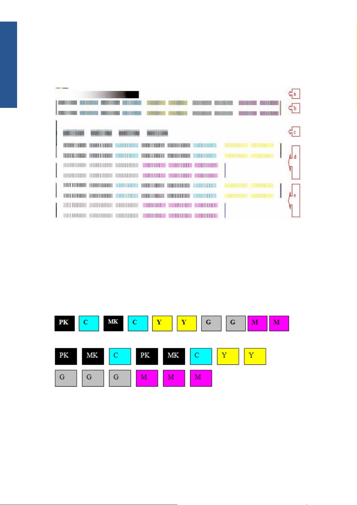
The illustration shows the complete Printhead Alignment that identifies each of the specific alignment test
results covered.
The Printhead Alignment Diagnostic print shows the following diagnostic test results:
a Line Sensor Calibration
b Pen to Pen Align
c Carriage thetaZ
d Bidirectional align (high
e Bidirectional align (Low)
For tests a, b, and c, the order of the color band is:
For tests e and f, the order of the color band is:
Once the printer has correctly printed and scanned the Printhead Alignment Diagnostic print, the Front
Panel displays the results. The top row displays the printhead, and the left column displays the test.
The results are separated onto two screens. Use the Arrow keys to display the second results screen.
16 Chapter 1 Troubleshooting ENWW
Troubleshooting
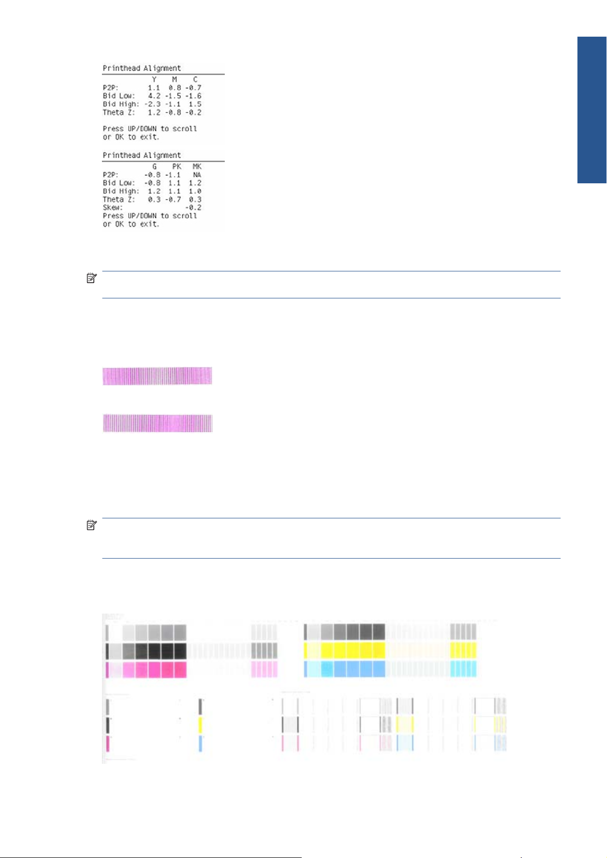
Any printhead with a test result containing a number that is not within the ±3 dot row range is
misaligned.
NOTE: The mK printhead is used as a reference to test the other printheads. If all the printheads fail
the Pen to Pen tests, it is the mK printhead that is misaligned.
Reading the Printhead Alignment Diagnostic Print
The following plot shows correct printhead alignment for all patterns. The clear band is in the center of
the pattern.
The following plot shows bad printhead alignment. The clear band is not in the center of the pattern.
Corrective action
●
If any of the printheads are misaligned beyond the ±3 dot row range, perform a Printhead
Alignment.
●
If a Printhead Alignment does not correct the problem, replace the bad printhead.
NOTE: If the customer is using non-HP paper and after the Image Quality Test you still have the same
image quality problems, change to genuine HP paper and repeat the Image Quality Test. The best
alignment calibration is obtained using HP Photo Paper.
Nozzle Health
The print contains three separate parts.
ENWW
Print-quality troubleshooting
17
Troubleshooting

a The Variable Frequency Nozzle health plot with odd/even nozzles separation. This is used to detect
misdirected nozzles, weak nozzles, or nozzles not working correctly at all frequencies.
b Inspector measuring tool test plot.
NOTE: Test b should not be used by Service Engineers.
c Nozzle Print Test which is also part of the Image Quality Service Plot. This test is designed to
check that the Printhead nozzles print correctly. The test prints out every single nozzle of each
Printhead. No error hiding or Printhead Alignment algorithm is applied. For each Printhead, you can
see both the adjacent and the consecutive nozzles.
This is what you would see in the Nozzle Print Test part if there are nozzles not printing correctly:
1. On the right of each Printhead Nozzle test, there is a series of numbered stepped diagonal lines.
If one or more of the nozzles are malfunctioning or mis-positioned, you will see that the stepped
lines are broken or misdirected in one or more places.
2. On the left of each Printhead Nozzle test, there is a series of horizontal straight lines. If one or
more nozzles are misdirected there will be unequal spaces between the corresponding lines.
Corrective action for Nozzle Defects
If the printer has nozzle defects, it does not mean that you will not get perfect print quality results. The
printer has automatic procedures to hide many nozzle defects.
1. Recover the Printheads using the option through the Front Panel (Main menu/Image quality
maintenance/clean printheads).
2. Reprint the Nozzle Print test to check that the defective nozzles have been corrected.
3. If the problem continues, replace the defective Printhead.
Force Drop Detection
If the Nozzle Print Test plot has persistent white point banding in only one color that cannot be fixed
with a printhead recovery, you can use this option to resolve the problem by resetting the nozzle health
database so that all nozzles are assumed to be correct.
Once the nozzle health database has been reset, drop detection is forced.
The normal cause of this white point banding in a single color is the incorrect detection of failed
nozzles by the drop detector.
Perform the test as follows.
1. Select Advanced Diagnostic Print.
2. Select Force Drop Detection.
18 Chapter 1 Troubleshooting ENWW
Troubleshooting
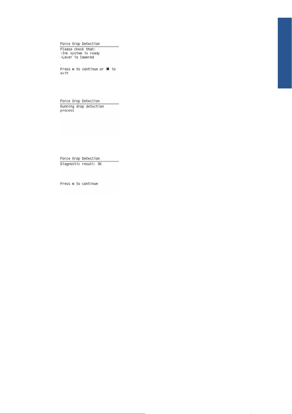
3. Make sure the Media Lever is lowered and the ink system ready, then press OK.
4. The printer runs the drop detection.
5. Press OK to end the test and return to the menu.
Troubleshooting print-quality problems
General advice
1. To achieve the best performance from the printer, only genuine HP accessories and supplies
should be used.
2. Make sure that the paper type selected in the Front Panel is the same as the paper type loaded
into the printer.
3. Make sure to use the most appropriate print quality settings for your purposes. A lower print
quality is likely to be seen if the print quality slider has been moved to the Speed end of the
scale, or the custom quality level set to Fast.
4. Check that the environmental conditions (temperature, humidity) are within the temperature/
humidity range as specified for the printer (refer to the User’s Guide for more information).
5. Check that the ink cartridges and printheads have not exceeded their expiration dates.
Horizontal lines across the image (banding)
When you look at the image you have printed, there are horizontal lines across the print. Here are two
examples of what you might see if you have this problem:
ENWW
Print-quality troubleshooting
19
Troubleshooting

Corrective action
1. Check that the paper type loaded corresponds to the paper type selected in the front panel and in
the software. You can check the paper type selected by pressing the View information key on
the Front Panel.
2. Check that the appropriate print quality settings are being used (refer to the User’s Guide for more
information) and reprint the image. In some cases print quality problems can be resolved by
selecting a higher print quality level.
3. Print the Service Image Diagnostics Print, and clean any printheads that need cleaning. Reprint the
job in case the problem has been solved.
4. Check the paper advance calibration status. If the status is PENDING, calibrate the paper
advance: at the Front Panel, select the Image Quality Maintenance icon, then Paper advance
calibration > Calibrate paper advance.
5. After calibration, reprint the job.
6. Try again with a new roll of paper.
7. Watch the printer carriage when it reaches the end of its swath. If there is an unexpected delay,
this may cause the banding.
If this is the case, the following corrective measures can be taken:
●
Do not use the computer while printing. Close applications that use a large amount of
computer resources.
●
Convert the file to PDF. Formats like PDF require less resources to print, which may solve your
banding problem.
This delay is possibly the result of the following:
●
The user is performing tasks with other applications while printing (particularly image
processing applications). These applications are using too many computer resources, and the
computer cannot effectively process the print job.
●
The file to be printed is complex, and the computer does not have the capacity to print such
complex files.
●
If printing over a LAN, it is possible that the LAN is too slow to meet the requirements of the
print job.
20 Chapter 1 Troubleshooting ENWW
Troubleshooting
Lines are missing, too thin, or too thick
Shown below is an example of what you might see if you have this problem:
Corrective action
1. Check that the paper type loaded corresponds to the paper type selected in the front panel and in
the software. You can check the paper type selected by pressing the View information key on
the Front Panel.
2. Check that the appropriate print quality settings are being used (refer to the User’s Guide for more
information). Select the custom print quality options in the Print dialog, and if you are using best
quality and glossy paper, try turning on the Maximum detail option. Reprint the job in case the
problem has been solved.
3. If the resolution of the image is greater than the printing resolution, a loss of line quality may be
seen. You can find the Max. Application Resolution option in the Windows driver dialog's
Advanced tab, under Document Options > Printer Features. Reprint the job in case the problem
has been solved.
4. Check the Printhead alignment status. If the status is PENDING, perform the Printhead Alignment
(Main Menu/Image Quality Maintenance/Align Printheads). After alignment reprint the job.
5. Check the paper advance calibration status. If the status is PENDING, calibrate the paper
advance: at the Front Panel, select the Image Quality Maintenance icon, then Paper advance
calibration > Calibrate paper advance. After calibration, reprint the job.
6. Use Part 3 of the Image Quality Diagnostic Print, check if there are a significant amount of nozzles
out in the color that is actually causing the problem (if see you a problem with the Black color
in the customer print, then only check the Black printhead in the Image Quality Diagnostic Print). If
there is a significant amount of nozzles out then replace the defective Printhead.
Problems with stepped lines
When you look at the image you have printed there are 'stepped lines' in the borders of arrows and
diagonal lines. The lines should be straight with no stepping.
Shown below is an example of what you might see if you have problems with Stepped Lines:
ENWW
Print-quality troubleshooting
21
Troubleshooting

Corrective action
1. The problems may be inherent in the image that you are trying to print. Try to improve the image
with the application that generated the file.
2. Check that the appropriate print quality settings are being used (refer to the User’s Guide for more
information).
3. Select the custom print quality options in your Print dialog, and if you are using Glossy paper and
BEST quality, turn on the Maximum Detail option.
4. Change the image rendering resolution to 300 dpi (only in EconoMode Printmode) or 600 dpi
depending on the printing needs. You can find the Max. Application Resolution option in the
Windows driver dialog's Advanced tab, under Document Options > Printer Features.
Lines are printed double or in wrong colors
This problem can have various visible symptoms, as shown below:
Corrective action
▲
Reseat the printheads by removing them and then reinserting them.
NOTE: As you reseat the printheads, the printer will automatically align the printheads. It is
important that the alignment is completed properly.
Lines are discontinuous
If the lines are broken in the following way:
22 Chapter 1 Troubleshooting ENWW
Troubleshooting

1. Check that the appropriate print quality settings are being used (refer to the User’s Guide for more
information).
2. Reseat the printheads by removing them and then reinserting them.
NOTE: As you reseat the printheads, the printer will automatically align the printheads. It is
important that the alignment is completed properly.
Lines are blurred (ink bleeds from lines)
This problem is often caused by the ink soaking into the paper, making the lines blurred and fuzzy. This
could be because of the humidity in the air.
Corrective action
1. Check that the environmental conditions (temperature, humidity) are suitable for high-quality
printing.
2. Make sure that the paper type selected in the Front Panel is the same as the paper type loaded
into the printer.
3. Try using a heavier paper type. When printing dense colors, it is recommended to use HP
Heavyweight Coated Paper or HP Super Heavyweight Coated Paper.
4. If glossy paper is being used, try changing to a different type of glossy paper.
5. Align the printheads. See
Image Quality Maintenance Procedure on page 43.
6. Try rotating the image.
ENWW
Print-quality troubleshooting
23
Troubleshooting

Problems with graininess
Shown below is an example of what you might see if you have problems with graininess:
Corrective action
1. Check that the paper type loaded corresponds to the paper type selected in the front panel and in
the software. You can check the paper type selected by pressing the View information key on
the Front Panel.
2. Check that printing is on the correct side of the paper.
3. Check that the appropriate print-quality settings are being used (refer to the User’s Guide for more
information). In many cases, you can correct grainy printing by raising the print-quality level.
Reprint the job in case the problem has been solved.
4. Reseat the printheads by removing and then reinserting them.
NOTE: As you reseat the printheads, the printer will automatically align them. It is important that
the alignment is completed properly.
5. Check the paper advance calibration status. If the status is PENDING, calibrate the paper
advance: at the Front Panel, select the Image Quality Maintenance icon, then Paper advance
calibration > Calibrate paper advance.
6. After paper advance calibration, reprint the job.
7. If there is only a strip of grain at the top of the job, try leaving a white margin of 5 cm before the
job, or load a new roll of paper (with less paper curl).
Paper is not flat
If the paper does not lie flat when it comes out of the printer, but has shallow waves in it, you are likely
to see visible defects in the printed image, such as vertical stripes. This can happen when you use thin
paper that becomes saturated with ink.
Shown below is an example of what you might see if you have problems with the paper not being flat:
24 Chapter 1 Troubleshooting ENWW
Troubleshooting
Loading...