


 Loading...
HP SureStore DLT Tape Library
User’s Guide
Models 4115w/4215w,
7115w/7215w
Part Number C5173-90000
Edition 4
September 1998
Printed in United States
© Copyright 1998 Hewlett-Packard Company

Notices
This document contains information that is protected by copyright. All rights are reserved. No part of this document may be photocopied, reproduced, or translated into another language without the prior written consent of Hewlett-Packard Company. The information contained in this document is subject to change without notice.
Hewlett-Packard makes no warranty of any kind with regard to this printed material, including, but not limited to, the implied warranties of merchantability and fitness for a particular purpose. Hewlett-Packard shall not be liable for errors contained herein or for incidental or consequential damages in connection with the furnishing, performance, or use of this material.
See Appendix B for important safety and regulatory information.
Printing History
New editions of this manual incorporate all material updated since the previous edition. The manual printing date and part number indicate the current edition. The printing date changes when a new edition is printed. (Minor corrections and updates incorporated at reprint do not cause this date to change.)
September, 1997 |
Edition 1 |
November, 1997 |
Edition 2 |
February, 1998 |
Edition 3 (TapeAlert and TapeAssure added) |
September 1998 |
Edition 4 (Enhancements added) |
ii

In This Book
This book is a guide for setting up and operating your tape library. It is organized as follows:
Chapter 1
Chapter 2
Chapter 3
Appendix A
Appendix B
Appendix C
Glossary
iii

NOTE
CAUTION
WARNING
Typographical Conventions
This manual uses the following typographical conventions:
Font |
Used for |
|
|
Italics |
Document titles and statements that need to be |
|
emphasized. |
|
|
COMPUTER OUTPUT |
Information displayed in the control panel or |
|
screen menu items that you can select. |
|
|
KEYCAP TEXT |
Keys on the library control panel. |
|
|
Notes provide information that can be helpful in understanding the operation of the product.
Cautions call attention to an operating procedure or practice that could result in damage to the product if not correctly performed. Do not proceed beyond this box until you fully understand and meet the indicated conditions.
Warnings call attention to a procedure or practice that could result in personal injury if not correctly performed. Do not proceed beyond this box until you fully understand and meet the indicated conditions.
This warning symbol on a product label indicates that personal injury could result if the product is used improperly, and that more detailed information is given in the installation and/or user manuals.
iv

Contents
1. Installing the Tape Library |
|
Installation Overview ..................................................................... |
1-2 |
Step 1: Choose a Location ............................................................. |
1-3 |
Step 2: Unpack the Library ............................................................ |
1-4 |
Required Components ................................................................. |
1-4 |
Additional Components Provided ............................................... |
1-5 |
Tape Library Rear Panel ............................................................. |
1-6 |
Step 3: Install the Host SCSI Card(s) ............................................ |
1-7 |
Step 4: Mount the Library in a Rack (optional) ............................. |
1-8 |
Safety Precautions ....................................................................... |
1-8 |
Tools and Components ............................................................... |
1-9 |
Mounting the Library ................................................................ |
1-10 |
Attach the Mounting Brackets ............................................... |
1-10 |
Attach the Rack Slides to the Rack ........................................ |
1-12 |
Place the Library in the Rack ................................................. |
1-17 |
Step 5: Set the SCSI Interface Mode Switch ............................... |
1-20 |
Step 6: Connect Library to Host .................................................. |
1-23 |
Routing SCSI and Power Cables on Rack Mounted Libraries . 1-23 |
|
Step 7: Power On the System ...................................................... |
1-27 |
Install Backup Software ............................................................ |
1-27 |
Verify Installation With TapeAssure ........................................ |
1-27 |
Moving or Shipping the Library .................................................. |
1-28 |
2. Using Tape Cartridges |
|
Tape Cartridge Overview ............................................................... |
2-2 |
Contents of Table
v

Contents
Choosing Tape Cartridges ............................................................. |
2-3 |
Labeling Tape Cartridges ............................................................... |
2-4 |
Labeling Bulk Load Magazines ..................................................... |
2-5 |
Drive Cleaning Messages .............................................................. |
2-6 |
Write-Protecting Tape Cartridges .................................................. |
2-8 |
Maintaining Tape Cartridges ......................................................... |
2-9 |
3. Operating the Library |
|
Overview ........................................................................................ |
3-2 |
Operating the Control Panel .......................................................... |
3-3 |
Understanding Display Window Messages ................................... |
3-4 |
Drive Status ................................................................................. |
3-4 |
Status Indicators ....................................................................... |
3-4 |
Activity Indicators ................................................................... |
3-5 |
Control Panel Options ................................................................. |
3-6 |
First Level Options .................................................................. |
3-6 |
Second Level Options .............................................................. |
3-7 |
Control Panel Menu Tree ............................................................ |
3-8 |
Entering the Administration Menu Password ............................... |
3-9 |
Setting a New Administration Menu Password ........................... |
3-10 |
Setting and Viewing SCSI IDs .................................................... |
3-11 |
Setting SCSI IDs ....................................................................... |
3-12 |
Interpreting SCSI Bus Status Indicator LEDs ....................... |
3-14 |
Viewing Current SCSI Address Settings .................................. |
3-14 |
Loading Tape Cartridges Into the Library ................................... |
3-15 |
vi

Contents
Inserting/Removing Cartridges with Software |
......................... 3-15 |
Keeping Cartridges in the Magazine ........................................ |
3-15 |
Loading Tapes ........................................................................... |
3-16 |
Removing Tape Cartridges from the Library ............................. |
3-19 |
Viewing Cartridge Bar Code Labels ............................................ |
3-22 |
Cleaning the Library Tape Drives ............................................... |
3-23 |
Setting Configuration Options ..................................................... |
3-25 |
Retrieving Performance Information ........................................... |
3-28 |
Running an Internal Test .............................................................. |
3-33 |
Using Online Drive Replacement ................................................ |
3-37 |
Troubleshooting ........................................................................... |
3-39 |
A. Supplies and Customer Support |
|
Overview ....................................................................................... |
A-2 |
Supplies and Accessories .............................................................. |
A-3 |
Hewlett-Packard Customer Support ............................................. |
A-6 |
HP FIRST/QUICK FAX Faxback Services .............................. |
A-6 |
Asia-Pacific ............................................................................. |
A-7 |
Europe ..................................................................................... |
A-8 |
North and South America (includes Canada) ......................... |
A-8 |
Other Countries ....................................................................... |
A-8 |
Electronic Support Services ....................................................... |
A-9 |
On-line Service Providers ....................................................... |
A-9 |
Hewlett-Packard Web Site ...................................................... |
A-9 |
Customer Support Centers ....................................................... |
A-10 |
Contents of Table
vii

Contents
North and South America (includes Canada) ....................... |
A-10 |
European Customer Support Centers .................................... |
A-10 |
Asia-Pacific ........................................................................... |
A-11 |
Elsewhere .............................................................................. |
A-11 |
Telephone Support After Warranty ......................................... |
A-12 |
Before Calling ....................................................................... |
A-12 |
US and Canada ...................................................................... |
A-12 |
Europe ................................................................................... |
A-12 |
Elsewhere .............................................................................. |
A-12 |
HP Reseller Locator Numbers .............................................. |
A-12 |
B. Safety and Regulatory Information |
|
Overview ........................................................................................ |
B-2 |
Safety Information ......................................................................... |
B-3 |
Laser Safety ................................................................................ |
B-3 |
CDRH Regulations (USA Only) ................................................ |
B-3 |
Regulatory Information .................................................................. |
B-4 |
Declaration of Conformity .......................................................... |
B-5 |
United Kingdom Telecommunications Act 1984 ....................... |
B-6 |
Herstellerbescheinigung .............................................................. |
B-6 |
English Translation of German Sound Emission Directive ..... |
B-6 |
Turvallisuusyhteenveto ............................................................... |
B-7 |
English Translation of Finnish Regulatory Information .......... |
B-8 |
Japanese VCCI Statement ........................................................... |
B-9 |
English Translation of Japanese VCCI Statement ................... |
B-9 |
viii

Contents
C. TapeAlert Messages |
|
Overview ........................................................................................ |
C-2 |
TapeAlert Messages and Descriptions ........................................... |
C-3 |
Contents of Table
ix

Contents
x
Figures
Figure 1-1. Rear Panel Features. . . . . . . . . . . . . . . . . . . . . . . . . . . . . . |
. 1-6 |
Figure 1-2. Rackmounting Components . . . . . . . . . . . . . . . . . . . . . . . . |
. 1-9 |
Figure 1-3. Rack Slides . . . . . . . . . . . . . . . . . . . . . . . . . . . . . . . . . . . . . |
1-10 |
Figure 1-4. Front Mounting Bracket . . . . . . . . . . . . . . . . . . . . . . . . . . |
1-11 |
Figure 1-5. Rear Mounting Bracket . . . . . . . . . . . . . . . . . . . . . . . . . . . |
1-11 |
Figure 1-6. Clip Nuts (Front Rails). . . . . . . . . . . . . . . . . . . . . . . . . . . . |
1-12 |
Figure 1-7. Clip Nuts (Back Rails) . . . . . . . . . . . . . . . . . . . . . . . . . . . . |
1-13 |
Figure 1-8. Front Bracket on Rack . . . . . . . . . . . . . . . . . . . . . . . . . . . . |
1-14 |
Figure 1-9. Rear Bracket on Rack. . . . . . . . . . . . . . . . . . . . . . . . . . . . . |
1-15 |
Figure 1-10. Bezel Spacers . . . . . . . . . . . . . . . . . . . . . . . . . . . . . . . . . . |
1-16 |
Figure 1-11. Strain Relief Bracket . . . . . . . . . . . . . . . . . . . . . . . . . . . . |
1-17 |
Figure 1-12. Library on Slides . . . . . . . . . . . . . . . . . . . . . . . . . . . . . . . |
1-18 |
Figure 1-13. Installation Handles. . . . . . . . . . . . . . . . . . . . . . . . . . . . . |
1-18 |
Figure 1-14. Front Access Door. . . . . . . . . . . . . . . . . . . . . . . . . . . . . . . |
1-19 |
Figure 1-15. SCSI Interface Mode Switch (Example) . . . . . . . . . . . . . |
1-20 |
Figure 1-16. SCSI/Power Cables and Strain Relief Bracket . . . . . . . . |
1-24 |
Figure 1-17. Front Access Door. . . . . . . . . . . . . . . . . . . . . . . . . . . . . . . |
1-25 |
Figure 1-18. Secured SCSI and Power Cables . . . . . . . . . . . . . . . . . . . |
1-26 |
Figure 2-1. Proper Label Position . . . . . . . . . . . . . . . . . . . . . . . . . . . . |
. 2-4 |
Figure 2-2. Magazine Label Position . . . . . . . . . . . . . . . . . . . . . . . . . . |
. 2-5 |
Figure 2-3. Write-Protect Button Settings . . . . . . . . . . . . . . . . . . . . . . . |
2-8 |
Figure 3-1. Tape Library Control Panel . . . . . . . . . . . . . . . . . . . . . . . . . |
3-3 |
Figure 3-2. Control Panel Menu Options . . . . . . . . . . . . . . . . . . . . . . . |
3-8 |
Figures of Table
xi

Figures
Figure 3-3. Opening the Front Access Door . . . . . . . . . . . . . . . . . . . . . 3-17 Figure 3-4. Loading Tape Cartridges into the Magazine . . . . . . . . . . . 3-17 Figure 3-5. Inserting Magazines . . . . . . . . . . . . . . . . . . . . . . . . . . . . . . 3-18 Figure 3-6. Opening the Front Access Door . . . . . . . . . . . . . . . . . . . . . 3-20 Figure 3-7. Removing Magazines . . . . . . . . . . . . . . . . . . . . . . . . . . . . .3-20
xii

Tables
Table 1-1. Location Criteria . . . . . . . . . . . . . . . . . . . . . . . . . . . . . . . . . . 1-3 Table 1-2. Components Included for Installation . . . . . . . . . . . . . . . . . 1-4 Table 1-3. Additional Components . . . . . . . . . . . . . . . . . . . . . . . . . . . . . 1-5 Table 1-4. SCSI Interface Mode Switch Settings . . . . . . . . . . . . . . . . . 1-20 Table 1-5. Tape Library as the Only Peripheral . . . . . . . . . . . . . . . . . 1-21 Table 1-6. Tape Library with Other Peripherals . . . . . . . . . . . . . . . . . 1-22 Table 2-1. Supported Tape Types . . . . . . . . . . . . . . . . . . . . . . . . . . . . . . 2-3 Table 2-2. Drive Cleaning Messages. . . . . . . . . . . . . . . . . . . . . . . . . . . . 2-7 Table 2-3. Tape Cartridge Maintenance . . . . . . . . . . . . . . . . . . . . . . . . . 2-9 Table 3-1. Default SCSI IDs . . . . . . . . . . . . . . . . . . . . . . . . . . . . . . . . . 3-11 Table 3-2. SCSI Address Configuration Options . . . . . . . . . . . . . . . . . 3-12 Table 3-3. SCSI Status Indicators . . . . . . . . . . . . . . . . . . . . . . . . . . . . 3-14 Table 3-4. Configuration Options . . . . . . . . . . . . . . . . . . . . . . . . . . . . . 3-26 Table 3-5. Information Logs . . . . . . . . . . . . . . . . . . . . . . . . . . . . . . . . . 3-29 Table 3-6. Internal Tests . . . . . . . . . . . . . . . . . . . . . . . . . . . . . . . . . . . . 3-34 Table 3-7. Troubleshooting Table . . . . . . . . . . . . . . . . . . . . . . . . . . . . . 3-39 Table A-1. Basic Supplies and Accessories. . . . . . . . . . . . . . . . . . . . . . . A-3 Table C-1. TapeAlert Tape Error Messages . . . . . . . . . . . . . . . . . . . . . . C-3 Table C-2. TapeAlert Library Error Messages . . . . . . . . . . . . . . . . . . . . C-6
Tables of Table
xiii

Tables
xiv

Installation
1 |
Installing the Tape Library |
1-1

Installing the Tape Library
Installation Overview
Installation Overview
|
Before you install the tape library: |
|
|
• Make sure you have the components listed in Table 1-2 on page 1-4. |
|
|
• Become familiar with the back of the tape library, as shown in “Tape Library |
|
|
|
Rear Panel” on page 1-4. |
|
To install the library, you must: |
|
|
1. |
Choose a location. |
|
2. |
Unpack the library. |
|
3. |
Install the SCSI host adapter card. |
|
4. |
Mount the library in a rack (rackmount configuration only). |
|
5. |
Set the SCSI interface mode switch. |
|
6. |
Connect the tape library. |
|
7. |
Power on the system. |
|
|
|
NOTE |
These steps are explained in this chapter. This chapter also explains how to move or |
|
|
ship the library. |
|
|
|
|
|
|
|
NOTE |
After the library is installed, you must perform additional tasks explained in |
|
|
Chapters 2 and 3. |
|
|
|
|
1-2

Installing the Tape Library
Step 1: Choose a Location
Step 1: Choose a Location
Choose a location that meets the following criteria. Take the library there before unpacking it.
Table 1-1 |
Location Criteria |
|
|
|
|
|
|
|
Room temperature |
50-104° F (10-40° C) |
|
|
|
|
|
|
Power source |
AC power voltage: 100-127 V or 200-240 V |
|
|
|
|
|
|
Air quality |
Minimal sources of particulate contamination. Avoid areas |
|
|
|
near frequently used doors and walkways, stacks of |
|
|
|
supplies that collect dust, and smoke-filled rooms. |
|
|
|
CAUTION: Excessive dust and debris can damage tapes |
|
|
|
and tape drives. |
|
|
|
|
|
|
Adequate |
Standalone configuration — free standing or against a |
|
|
clearance |
wall/desk: |
|
|
|
Back |
56 cm (22 in.) for cooling and service. |
|
|
Front |
86 cm (34 in.) for operator access. |
|
|
Sides |
56 cm (22 in.) for removal of the external |
|
|
|
cover. |
|
|
If less space is allowed, move the library to an open area |
|
|
|
before servicing. |
|
|
|
|
|
|
|
Rack mount configuration: |
|
|
|
Back |
Allow adequate room to open the rear door of |
|
|
|
the rack for service access, usually 46-61 cm |
|
|
|
(18-24 in.), depending on the rack. |
|
|
Front |
86 cm (34 in.) for operator access. |
|
|
Height |
For ease of use, install the library so the |
|
|
|
bottom is 60-120 cm (24-48 in.) above the |
|
|
|
floor. Do not install the library in the bottom |
|
|
|
rail position because of clearance. |
|
|
|
|
Installation
1-3

Table 1-2
NOTE
Installing the Tape Library
Step 2: Unpack the Library
Step 2: Unpack the Library
Make sure you have all required components and become familiar with the library’s components.
Required Components
Components Included for Installation
Component |
Description |
|
|
Tape Library |
Unpack the library when it is in the desired location. |
|
|
SCSI card(s) |
One single-ended FAST/WIDE SCSI is included with |
|
the library. Data is transferred up to 20 Mbytes/second. |
|
For FAST handshaking, the total length of the SCSI bus |
|
is limited to 3 meters. |
|
|
SCSI cable: |
One 3-meter single-ended FAST/WIDE SCSI is included |
allowable lengths |
with the library. |
|
|
Daisy-chain cable |
Included with two-drive libraries. |
|
|
Power cord |
Included with library. |
|
|
Rackmount kit |
Included with rackmount libraries. |
|
|
Data cartridge |
Five tapes are included with library. |
|
|
Cleaning cartridge |
One cleaning tape is included with library. |
|
|
Contact your service representative if you are missing any components.
1-4

|
|
|
Installing the Tape Library |
|
|
|
Step 2: Unpack the Library |
|
Additional Components Provided |
||
Table 1-3 |
Additional Components |
|
|
|
|
|
|
|
Component |
|
Description |
|
|
|
|
|
User’s Guide |
|
Printed user’s manual in English. |
|
|
|
|
|
DLT Library |
|
Online user’s manual with video clips. |
|
Advisor |
|
|
|
|
|
|
|
HP SureStore Tape |
|
Includes TapeAssure/TapeAlert, as well as other |
|
CD-ROM |
|
diagnostic utilities. Also includes the User’s Guide on |
|
|
|
CD-ROM, translated into French, Italian, German, |
|
|
|
Spanish, and Japanese. |
|
|
|
|
|
Live Trial Backup |
|
Includes live trial versions of backup software for your |
|
Software |
|
evaluation. |
|
|
|
|
|
Tape Data Sheet |
|
Describes the tape specifications, characteristics, and |
|
|
|
maintenance needed |
|
|
|
|
|
Bar Code Labels |
|
Includes bar code labels and reordering information. |
|
|
|
|
Installation
1-5

|
Installing the Tape Library |
|
Step 2: Unpack the Library |
|
Tape Library Rear Panel |
Figure 1-1 |
Rear Panel Features |
The following list identifies the numbered components in Figure 1-1:
1Bus 1 SCSI ports
2SCSI interface mode switch
3Bus 2 SCSI ports
4Power port
5SCSI bus indicator label
6SCSI bus status indicators
1-6
Installing the Tape Library
Step 3: Install the Host SCSI Card(s)
Step 3: Install the Host SCSI Card(s)
Install the single-ended or differential SCSI card into the host computer system.
Refer to the host user manual and the SCSI card installation instructions for information on installing and configuring SCSI cards.
Installation
1-7

WARNING
Installing the Tape Library
Step 4: Mount the Library in a Rack (optional)
Step 4: Mount the Library in a Rack (optional)
For stand-alone installations, go to “Step 5: Set the SCSI Interface Mode Switch” on page 1-20.
The rack slides can be adjusted to fit any standard rack with a depth of 26 to 31 inches (66.04 to 78.75 centimeters).
Safety Precautions
Because the tape library weighs approximately 100 pounds (45 kilograms), the following safety precautions must be taken when mounting the tape library:
•Fully extend the rack’s antitip rail and lower the leveller feet.
•Mount the tape library no higher than 4 feet (122 centimeters) in the rack.
•IMPORTANT: At least two people must lift the library during installation.
Do not pull the library out of the rack to its fully extended position unless the anti-tip rail on the bottom of the rack has been positioned correctly. Do not attempt to move the tape library by yourself.
The tape library weighs approximately 100 pounds (45 kilograms). Pulling the library out of the rack without the rack’s anti-tip rail extended could result in personal injury and/or damage to the tape library if the rack tips over.
1-8
Installing the Tape Library
Step 4: Mount the Library in a Rack (optional)
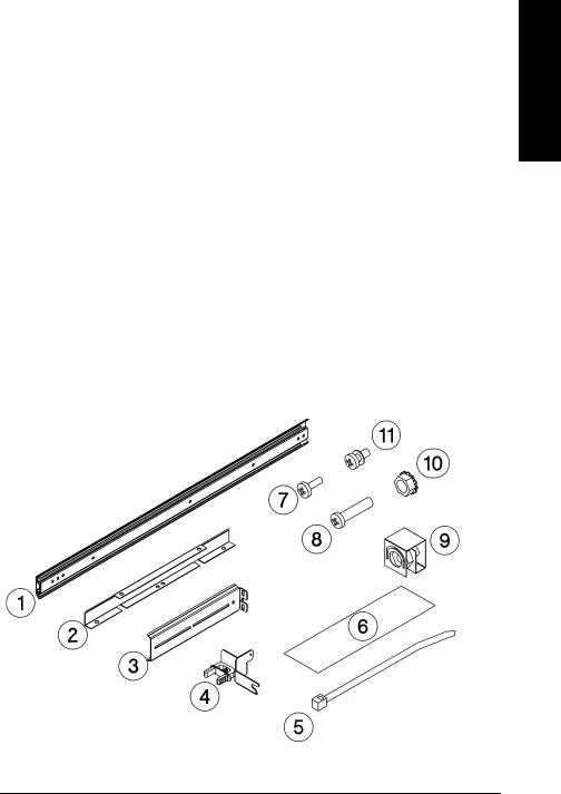
Tools and Components
|
Tools: |
|
|
|
|
Phillips screwdriver (included in kit) |
|
||
|
1/2 inch open-ended wrench |
|
|
|
|
Kit Hardware (parts are labeled for easy identification): |
|||
|
1. |
rack slides (1 pair) |
7. |
8-32 x 3/8 pan slotted phillips lw profile |
|
2. |
bezel spacers (2) |
|
hd (14) |
|
|
|
||
|
3. |
mounting brackets (4) |
8. |
10-32 x 5/8 pan slotted phillips (14) |
|
|
|
||
|
4. |
strain relief bracket (1) |
9. |
10-32 clip nuts (12) |
|
|
|
||
|
5. |
cable ties (4) |
10. |
8-32 keps nuts (8) |
|
|
|
||
|
6. |
template |
11. |
6-32 x 3/8 pan phillips, with internal |
|
|
lockwasher (1) |
||
|
|
|
|
|
Figure 1-2 |
Rackmounting Components |
|
|
|
Installation
1-9
Installing the Tape Library
Step 4: Mount the Library in a Rack (optional)
Mounting the Library
To mount the tape library in a rack, you must:
•First, attach the front and back mounting brackets to the rack slides.
•Next, attach the rack slides to the rack.
•Finally, attach the tape library to the rack slides.
These steps are explained in detail in the following sections.
Attach the Mounting Brackets
|
1. |
IMPORTANT: Lower the rack’s leveller feet using a 1/2-inch open-end wrench, |
|
|
and extend the rack’s antitip rail. |
|
|
|
WARNING |
Failure to extend the antitip rail could result in personal injury and/or damage |
|
|
to the tape library if the rack tips over. |
|
|
2. |
Pull the rack slide members out to the fully extended position. (The slides |
|
||
|
|
should “click” into a locked position.) |
Figure 1-3 |
Rack Slides |
|
1-10
Installing the Tape Library
Step 4: Mount the Library in a Rack (optional)
|
3. Attach the front mounting brackets to the front end of each slide using two 8-32 |
|
x 3/8 pan-slotted phillips screws and two 8-32 keps nuts. Tighten the screws. |
Figure 1-4 |
Front Mounting Bracket |
|
4. Attach the rear mounting brackets to the back side of each slide using two 8-32 x |
|
3/8 pan-slotted phillips screws and two 8-32 keps nuts. Do not tighten the |
|
screws. |
Figure 1-5 |
Rear Mounting Bracket |
Installation
1-11
|
Installing the Tape Library |
|
Step 4: Mount the Library in a Rack (optional) |
|
Attach the Rack Slides to the Rack |
|
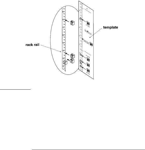
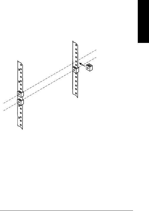
1. Line up the template with an existing product in the rack. Attach clip nuts to |
|
each front rail in the locations indicated on the template. |
Figure 1-6 |
Clip Nuts (Front Rails) |
NOTE |
Do not install the library in the bottom of the rack. Make sure the bottom of the |
|
library is no higher than 4 feet off the floor. |
|
|
1-12
|
Installing the Tape Library |
|
Step 4: Mount the Library in a Rack (optional) |
|
2. Attach two clip nuts to each of the back rails so that the slides will be level when |
|
attached to the rails. |
|
|
NOTE |
Count the holes on the front and back rails to ensure the slides will be level. |
|
|
Figure 1-7 |
Clip Nuts (Back Rails) |
Installation
1-13
Installing the Tape Library
Step 4: Mount the Library in a Rack (optional)
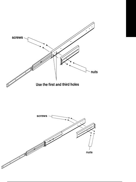
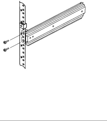
3.Attach the front bracket:
a.Return the slides to their compressed position.
b.Attach the front slide mounting bracket to the lower two clip nuts on the front rails using two 10-32 x 5/8 pan slotted phlp screws.
c.Push the slides as far as possible toward the outside of the rack.
d.Tighten the screws.
Figure 1-8 Front Bracket on Rack
1-14
|
|
Installing the Tape Library |
|
|
|
Step 4: Mount the Library in a Rack (optional) |
|
|
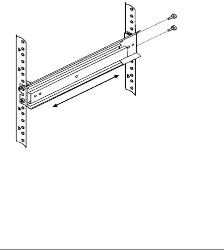
4. Attach the rear bracket: |
|
|
|
Installation |
||
|
a. Adjust the rear mounting brackets to fit lengthwise in the rack. |
||
|
|
||
|
b. |
Attach the rear slide mounting bracket to the rear clip nuts using two 10-32 x |
|
|
|
5/8 pan slotted phlp screws. |
|
|
c. Push the slides as far as possible toward the outside of the rack. |
|
|
|
d. |
Tighten the screws. |
|
|
e. |
Tighten all bracket screws. |
|
Figure 1-9 |
Rear Bracket on Rack |
|
|
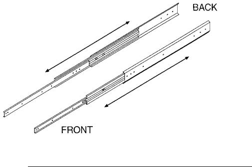
5. Extend the slides fully, make sure they are parallel, and then recompress them.
1-15
|
Installing the Tape Library |
|
Step 4: Mount the Library in a Rack (optional) |
|
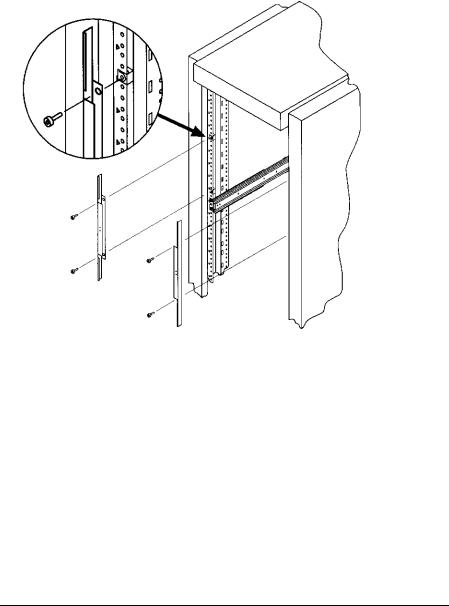
6. Connect the two bezel spacers to the front rails using two 10-32 x 5/8 pan slotted |
|
phlp screws. The screws attach to the two clip nuts on the front rails above the |
|
slides. |
Figure 1-10 |
Bezel Spacers |
1-16
Loading...