

Page 1

StoreOnce 3100, StoreOnce 3500 Series,
and StoreOnce 5100 Systems Maintenance
and Service Guide
Abstract
This document is the Maintenance and Service guide for the HPE StoreOnce 3100, 3520, 3540,
and 5100 Systems. These products are single node StoreOnce Systems, running StoreOnce
software version 3.14.0 or later. All tasks described in this guide require an Administrator logon.
Part Number: BB913-90959
Published: March 2017
Edition: 3
Page 2

©
2015, 2017 Hewlett Packard Enterprise Development LP
Notices
The information contained herein is subject to change without notice. The only warranties for Hewlett Packard
Enterprise products and services are set forth in the express warranty statements accompanying such
products and services. Nothing herein should be construed as constituting an additional warranty. Hewlett
Packard Enterprise shall not be liable for technical or editorial errors or omissions contained herein.
Confidential computer software. Valid license from Hewlett Packard Enterprise required for possession, use,
or copying. Consistent with FAR 12.211 and 12.212, Commercial Computer Software, Computer Software
Documentation, and Technical Data for Commercial Items are licensed to the U.S. Government under
vendor's standard commercial license.
Links to third-party websites take you outside the Hewlett Packard Enterprise website. Hewlett Packard
Enterprise has no control over and is not responsible for information outside the Hewlett Packard Enterprise
website.
Acknowledgments
Intel®, Itanium®, Pentium®, Intel Inside®, and the Intel Inside logo are trademarks of Intel Corporation in the
United States and other countries.
Microsoft® and Windows® are either registered trademarks or trademarks of Microsoft Corporation in the
United States and/or other countries.
Adobe® and Acrobat® are trademarks of Adobe Systems Incorporated.
Java® and Oracle® are registered trademarks of Oracle and/or its affiliates.
UNIX® is a registered trademark of The Open Group.
Page 3

Contents
Finding part numbers for replacement parts............................................ 6
General precautions and safety guidelines............................................ 19
HPE StoreOnce and HPE ProLiant..................................................................................................... 6
To access ProLiant documentation...........................................................................................6
HPE StoreOnce 3100 System Components........................................................................................6
HPE StoreOnce 3100 mechanical and system components.................................................... 8
HPE StoreOnce 3500 Series Components......................................................................................... 9
HPE StoreOnce 3500 and 5100 mechanical and system components.................................. 11
HPE StoreOnce 5100 System Components......................................................................................12
HPE StoreOnce 5100 mechanical and system components.................................................. 14
HPE StoreOnce 5100 System Capacity Upgrade Kit Components...................................................15
HPE StoreOnce 5100 System Capacity Upgrade System components.................................17
Optional Hardware Components....................................................................................................... 17
Required tools................................................................................................................................... 19
Component replacement guidelines..................................................................................................19
Safety precautions.............................................................................................................................19
General precautions............................................................................................................... 19
Preventing electrostatic discharge..........................................................................................20
Equipment symbols................................................................................................................ 20
Identifying problems................................................................................. 21
POST messages and troubleshooting...............................................................................................21
Using the StoreOnce GUI to identify a problem................................................................................ 21
Alerts in the Events Log..........................................................................................................21
Failed disk in the Hardware tree.............................................................................................21
Using the StoreOnce CLI to identify a problem................................................................................. 22
Overview.................................................................................................................................22
Identifying a problem.............................................................................................................. 22
LEDs and problem diagnosis.............................................................................................................24
Server LEDs (all models)........................................................................................................24
Front panel LEDs.........................................................................................................25
Disk drive LEDs........................................................................................................... 27
Rear panel LEDs..........................................................................................................28
Storage enclosure LEDs (HPE StoreOnce 5100 System only).............................................. 29
Front View LEDs..........................................................................................................29
Rear view LEDs........................................................................................................... 30
HPE StoreOnce 5100 System expansion shelf error messages............................................ 32
I/O module errors.........................................................................................................33
I/O module firmware errors.......................................................................................... 33
SAS cable error............................................................................................................33
Thermal control errors..................................................................................................34
Thermal shutdown alarms............................................................................................34
Power supply module errors........................................................................................ 34
Power supply communication errors............................................................................35
Fan module errors........................................................................................................35
Contents 3
Page 4

Powering on and off, firmware upgrades, and other processes...........36
Preparing for StoreOnce maintenance .............................................................................................36
Requirements for powering on and off ............................................................................................. 36
HPE StoreOnce Remote Support......................................................................................................36
Upgrading BIOS or hardware firmware components.........................................................................37
Updating firmware using the StoreOnce GUI......................................................................... 37
Updating firmware using the StoreOnce CLI.......................................................................... 38
Upgrading StoreOnce software......................................................................................................... 38
Running a system self test................................................................................................................ 39
HPresetpassword account.................................................................................................................40
The purpose of the HPresetpassword account ......................................................................40
Changing the password for the HPresetpassword account....................................................40
Resetting the password for the local Admin user................................................................... 40
Replacing the StoreOnce System motherboard .................................... 42
Motherboard replacement tasks specific to HPE StoreOnce Systems..............................................42
Identifying the Activation Key for the iLO4 license............................................................................ 42
Before replacing the motherboard—component configuration.......................................................... 42
Motherboard spares part number and System Maintenance switch................................................. 43
DIMM locations..................................................................................................................................43
After replacing the motherboard—BIOS and iLO configuration.........................................................45
RBSU settings................................................................................................................................... 49
iLO4 settings......................................................................................................................................50
Replacing the p1224 RAID controller and components.........................51
RAID controller component overview................................................................................................ 51
Part numbers.......................................................................................................................... 51
Internal SAS cabling..........................................................................................................................51
HPE StoreOnce 3100 System internal SAS cabling...............................................................51
HPE StoreOnce 3500 Series internal SAS cabling.................................................................52
HPE StoreOnce 5100 System internal SAS cabling...............................................................53
System boot and RAID controller failure........................................................................................... 53
Replacing the RAID components...................................................................................................... 54
p1224 RAID controller............................................................................................................ 54
The RAID cache module and SuperCapacitor........................................................................55
HPE SAS expander card (HPE StoreOnce 5100 System and HPE StoreOnce 3500
Series).................................................................................................................................... 55
Replacing the HPE SAS expander card................................................................................. 56
Disk replacement....................................................................................... 58
Disk numbering..................................................................................................................................58
RAID configuration............................................................................................................................ 58
Hot spare disk and LEDs on the HPE StoreOnce 5100 System............................................ 59
Ordering the correct replacement disk for a failed disk..................................................................... 59
Replacing a hot-plug hard disk .........................................................................................................60
Rebuilding storage if multiple disks fail and a RAIDset is broken......................................................62
StoreOnce Optional Hardware..................................................................63
Support for StoreOnce Optional Hardware .......................................................................................63
Error messages................................................................................................................................. 63
4 Contents
Page 5

Replacing Optional Hardware cards..................................................................................................64
Fibre Channel card considerations....................................................................................................64
Removing and replacing a Fibre Channel or 10 GbE optical SFP.................................................... 65
HPE StoreOnce 5100 System Capacity Upgrade expansion shelves...66
HPE StoreOnce 5100 System Capacity Upgrade hot-pluggable components..................................66
Removing and replacing the I/O module........................................................................................... 66
Removing and replacing a power supply module..............................................................................68
Removing and replacing a fan module..............................................................................................69
Replacing the fan control card...........................................................................................................70
Removing and replacing the power distribution board...................................................................... 71
Removing and replacing the enclosure backplane............................................................................72
Removing and replacing an enclosure.............................................................................................. 75
The QR ISO image..................................................................................... 78
The StoreOnce QR ISO image..........................................................................................................78
Download Quick Restore ISO Image ................................................................................................78
Create a bootable QR USB Stick...................................................................................................... 78
Delete storage................................................................................................................................... 79
Boot the appliance and install the StoreOnce software ....................................................................79
Performing a configuration restore ................................................................................................... 80
Support and other resources................................................................... 82
Accessing Hewlett Packard Enterprise Support................................................................................ 82
Accessing updates............................................................................................................................ 82
Customer self repair.......................................................................................................................... 82
Remote support.................................................................................................................................83
Warranty information......................................................................................................................... 83
Regulatory information...................................................................................................................... 83
Documentation feedback...................................................................................................................84
Additional regulatory information............................................................85
Belarus Kazakhstan Russia marking.................................................................................................85
Turkey RoHS material content declaration........................................................................................86
Ukraine RoHS material content declaration...................................................................................... 86
Contents 5
Page 6

Finding part numbers for replacement parts
HPE StoreOnce and HPE ProLiant
This guide is the Maintenance and Service Guide for the products listed in the first column. The products are
based on HPE ProLiant Gen 9 servers and this guide supplements the HPE ProLiant Maintenance and
Service Guides.
For hardware issues on the HPE StoreOnce System, the appropriate ProLiant server guide is the primary
source of information and common spares part numbers.
This StoreOnce guide contains only information that is not included in existing product documentation.
Table 1: Identifying the correct HPE ProLiant Maintenance and Service Guide
HPE StoreOnce System Associated HPE product
HPE StoreOnce 3100 System HPE ProLiant DL360p 4LFF G9 server
HPE StoreOnce 3520 System HPE ProLiant DL380p 12LFF G9 server
HPE StoreOnce 3540 System HPE ProLiant DL380p 12LFF G9 server
HPE StoreOnce 5100 System HPE ProLiant DL380p 12LFF G9 server
To access ProLiant documentation
For more information about replaceable components that are standard for the ProLiant products:
Procedure
1. Go to http://www.hpe.com/info/enterprise/docs.
2. Select HPE ProLiant Gen9 server and Service & Maintenance Guides.
3. Scroll through the guides and select HPE ProLiant DL380 Gen9 Server Maintenance and Service
Guide or HPE ProLiant DL360 Gen9 Server Maintenance and Service Guide, as appropriate .
4. Open the guide and look at the Illustrated Parts Catalogue.
The following tables provide a checklist with part numbers of all replaceable components that are unique to
HPE StoreOnce Systems. These parts and their replacement procedures are not referenced in the relevant
HPE ProLiant server guide and are described only in this guide.
NOTE:
There is no specific match for the HPE StoreOnce 5100 System Capacity Upgrade in existing HPE
documentation, so the replacement procedures are documented fully in this guide.
HPE StoreOnce 3100 System Components
This model is based on an HPE ProLiant DL360 Gen9 server. The following table contains the Spares Part
Numbers for the main components in the server unit.
6 Finding part numbers for replacement parts
Page 7

NOTE:
This list is an offline list, created from partsurfer. If there is a problem with these Spares Part Numbers,
check the online source at: http://partsurfer.hpe.com/search.aspx. If the problem exists in the online
source, use the feedback form to log the problem: http://partsurfer.hpe.com/ContactUs.aspx.
Table 2: HPE StoreOnce 3100 System, BB913A
Part Spares Part Number Description Hot plug
2 TB hard disk drive 653948-001 SPS-DRV HD 2TB 6G
SAS 7.2K 3.5 DP MDL
SC
Power supply 754377-001 SPS-PS 500W FS
PlatinumPlus
Processor 762445-001 SPS-PRO E5-2620v3 6C
2.4GHz 85W
Memory DIMM 774172-001 SPS-MEMORY DIMM
16GB 2Rx4
PC4-2133R-15
System board 775400-001 SPS-PCA dl380/dl360
Gen9 SYS I/O
Backplane 775402-001 SPS-PCA DL380/DL360
Gen9 4-LFF SAS Bkpln
Processor heatsink 775403-001 SPS-Heatsink Scr Down/
Standrd DL360 Gen9
Fan module 775415-001 SPS-Fan Module dl360
Gen9
Yes
No, unless optional
second PSU connected
No
No
No
No
No
Yes
PCI riser 775421-001 SPS-PCI Riser PRI S1/2
dl360 Gen9
Internal SAS cable 780423-001 SPS-SAS power cable No
PCIe riser 785497-001 SPS-PCI Riser PRI S1
DL360 Gen9
RAID controller p1224 842475-001 SPS-PCA p1224 w/o
Encryption
Mini DIMM module
(cache module for p1224)
SuperCapacitor (for
p1224)
633542-001 SPS-BD DDR3 MINI
DIMM MOD 1Gx72
660093-001 SPS-CA CAPACITOR
36in FL
Finding part numbers for replacement parts 7
No
No
No
No
No
Page 8

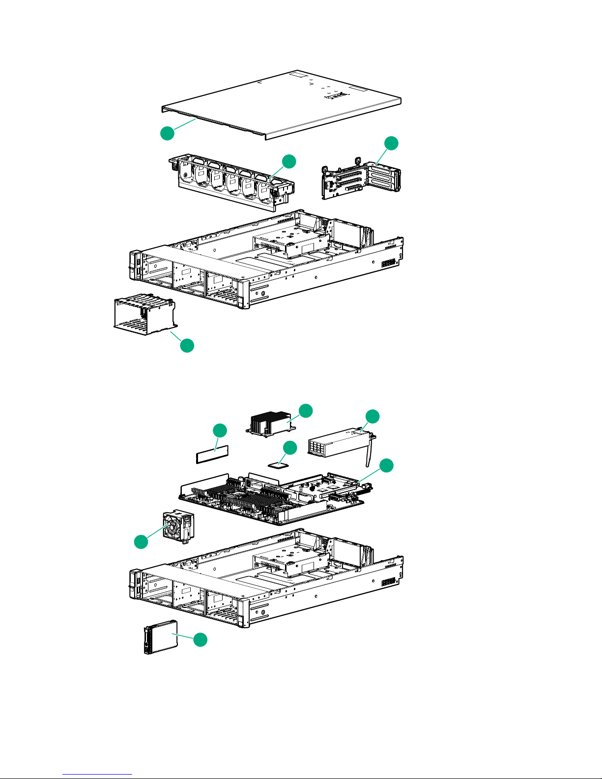
HPE StoreOnce 3100 mechanical and system components
1
2
3
4
5
6
7
8
10
9
11
12
Figure 1: HPE StoreOnce 3100 mechanical components
Figure 2: HPE StoreOnce 3100 system components
1 Access panel 2 PCI riser blank
3 PCI riser cage 4 Hot plug power supply
5 PCIe riser boards 6 Controller options
8 HPE StoreOnce 3100 mechanical and system components
Table Continued
Page 9

7 Heatsink 8 Processor
9 DIMM 10 System I/O board
11 Fan 12 Drive
HPE StoreOnce 3500 Series Components
The HPE StoreOnce 3520 System and HPE StoreOnce 3540 System are based on an HPE ProLiant DL380
Gen9 server. Both models have a base configuration of 12 LFF disks, with basic storage capacity capped at
50% of the available usable capacity. A license is required to make the full storage capacity available for use.
Optional hardware — 10GbE Network cards, FC cards, and SFP transceivers are not part of the basic
configuration.
The following table lists Spares Part Numbers for the main components in the server unit.
NOTE:
This list is an offline list, created from partsurfer. If there is a problem with these Spares Part Numbers,
check the online source at: http://partsurfer.hpe.com/search.aspx. If the problem exists in the online
source, use the feedback form to log the problem: http://partsurfer.hpe.com/ContactUs.aspx.
Table 3: HPE StoreOnce 3500 Series, BB914A and BB922A
Part Spares Part Number Description Hot plug
Hard disk drive (2 TB,
3520)
Hard disk drive (4 TB,
3540)
Power supply 754381-001 SPS-PS 800W FS
Processor 762445-001 SPS-PRO E5-2620v3 6C
Memory DIMM 774172-001 SPS-MEMORY DIMM
System board 775400-001 SPS-PCA dl380/dl360
PCIe riser card 1 PCA
(for PCIe slots 1 to 3)
653948-001 SPS-DRV HD 2TB 6G
SAS 7.2K 3.5 DP MDL
SC
695842-001 SPS-DRV HD 4TB 3.5
7.2K 6G SAS SC MDL
PlatinumPlus
2.4GHz 85W
16GB 2Rx4
PC4-2133R-15
Gen9 SYS I/O
777281-001 SPS-PCA dl380 3-S x8
PCI-E Riser
Yes
Yes
Yes
No
No
No
No
PCIe riser card 2 PCA
(for PCIe slots 4 to 6)
777283-001 SPS-PCA dl380 3-S 2
x16 x8 PCI-E riser2
HPE StoreOnce 3500 Series Components 9
No
Table Continued
Page 10

Part Spares Part Number Description Hot plug
Backplane 777284-001 SPS-PCA DL360/380 12-
No
LFF SAS Backplane
Fan module 777286-001 SPS-Fan Module (High
Yes
PERF) DL38x Gen9
Processor heatsink 777290-001 SPS-Heatsink ASSYSTD
No
105WDL380
Fan cage 777294-001 SPS-FAN CAGE DL38x No
Cable, HD Mini SAS to
Mini SAS, 16 inch
3500/5100 between the
SAS expander and the
694008–002 Cable, HD Mini SAS to
Mini SAS, 16 inch
3500/5100 Defender to
shiner
No
p1224
Internal SAS Ribbon
Cable from SAS
784627-001 SPS-CBL Mini SAS
12LFF + 15LFF Kit
No
expander to the
backplane
SAS expander 761879-001 SPS-BD Smart Array
No
PCIe SAS Expander
RAID controller p1224 842475-001 SPS-PCA p1224 w/o
Encryption
Mini DIMM module 633542-001 SPS-BD DDR3 MINI
DIMM MOD 1Gx72
SuperCapacitor (for
p1224)
660093-001 SPS-CA CAPACITOR
36in FL
No
No
No
10 Finding part numbers for replacement parts
Page 11
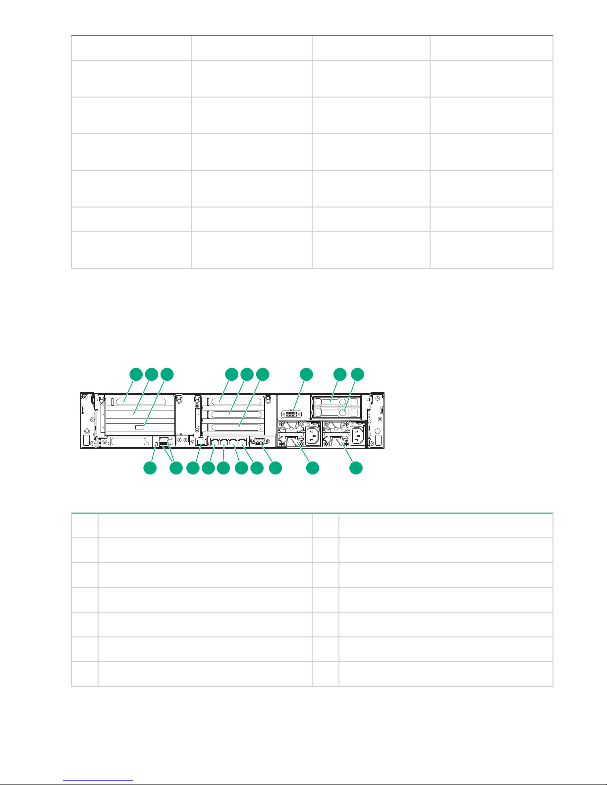
HPE StoreOnce 3500 and 5100 mechanical and system components
1
2
3
4
5
6
7
8
9
10
11
Figure 3: HPE 3500 and HPE 5100 Mechanical Components
Figure 4: HPE 3500 and HPE 5100 System Components
HPE StoreOnce 3500 and 5100 mechanical and system components 11
Page 12

1 Access panel 2 Fan cage
3 PCI riser 4 Drive cage
5 DIMMs 6 Heatsink
7 Processor 8 Power supply
9 System board assembly 10 Hard drive
11 Fan
For a rear view drawing of the HPE StoreOnce 3500 Series, see Figure 5.
HPE StoreOnce 5100 System Components
The HPE StoreOnce 5100 System is based on an HPE ProLiant DL380 Gen9 server. It has a base
configuration of 12 LFF disks for data storage and two disks for the operating system. Up to five 48 TB
Capacity Upgrade Kits may be connected to the base unit, each requires a separate license.
Optional hardware – 10GbE Network cards, FC cards, and SFP transceivers – are not part of the basic
configuration.
The following table lists Spares Part Numbers for the main components in the head server. See HPE
StoreOnce 5100 System Capacity Upgrade Kit Components on page 15 for information about
components in the storage enclosure.
NOTE:
This list is an offline list, created from partsurfer. If there is a problem with these Spares Part Numbers,
check the online source at: http://partsurfer.hpe.com/search.aspx. If the problem exists in the online
source, use the feedback form to log the problem: http://partsurfer.hpe.com/ContactUs.aspx.
Table 4: HPE StoreOnce 5100 System, BB915A
Part Spares Part Number Description Hot plug
OS Hard disk drive
(900GB)
Hard disk drive (4 TB) 695842-001 SPS-DRV HD 4TB 3.5
SmartArray RAID
Controller
SmartArray Battery Pack 815983-001 SPS-BATT PACK
Power supply 754381-001 SPS-PS 800W FS
653971-001 SPS-DRV HD 900GB 6G
SAS 10K 2.5 DP EN SC
7.2K 6G SAS SC MDL
749796-001 SPS-BD AROC P440ar
Cntrlr
ENHANCED MegaCell
96W
PlatinumPlus
Yes
Yes
No
No
Yes
12 HPE StoreOnce 5100 System Components
Table Continued
Page 13

Part Spares Part Number Description Hot plug
SAS expander 761879-001 SPS-BD Smart Array
PCIe SAS Expander
Cable, HD Mini SAS to
Mini SAS, 16 inch
3500/5100 between the
SAS expander and the
694008–002 Cable, HD Mini SAS to
Mini SAS, 16 inch
3500/5100 Defender to
shiner
p1224
Internal SAS Ribbon
Cable from SAS
784627-001 SPS-CBL Mini SAS
12LFF + 15LFF Kit
expander to the
backplane
RAID controller p1224 842475-001 SPS-PCA p1224 w/o
Encryption
Mini DIMM module
(cache module for p1224)
SuperCapacitor (for
p1224)
SAS/SATA backplane
board - Mounts on the
633542-001 SPS-BD DDR3 MINI
DIMM MOD 1Gx72
660093-001 SPS-CA CAPACITOR
36in FL
777280-001 SPS-PCA dl380 2-SFF
rear Backplane
rear of the 2-bay small
form factor (SFF) hard
drive cage
No
No
No
No
No
No
No
Mini-SAS cable kit
(Includes six cables) - For
connecting between the
8-bay and 2-bay small
784629-001 SPS-CA SAS 2SFF
+*SFF+
AROC/H240+P440 Kit
form factor (SFF) hard
drive cages and the H240
host bus adapter or the
P440ar controller board
Processor 762447-001 SPS-PRO E5-2640v3 8C
2.6GHz 90W
Memory DIMM 774172-001 SPS-MEMORY DIMM
16GB 2Rx4
PC4-2133R-15
System board 775400-001 SPS-PCA dl380/dl360
Gen9 SYS I/O
PCIe riser 1 PCA (for
PCIe slots 1 to 3)
777281-001 SPS-PCA dl380 3-S x8
PCI-E Riser
No
No
No
No
No
Table Continued
Finding part numbers for replacement parts 13
Page 14
Part Spares Part Number Description Hot plug
1
2
3
4
1
5
6
4
4
1
iLO
PS2
PS1
1 2 3 4 5 6 7 8 9
10111213141516171819
PCIe riser 2 PCA (for
PCIe slots 4 to 6)
777283-001 SPS-PCA dl380 3-S 2
x16 x8 PCI-E riser2
Backplane for data disks 777284-001 SPS-PCA DL360/380
12-LFF SAS Backplane
Fan module 777286-001 SPS-Fan Module (High
PERF) DL38x Gen9
Processor heatsink 777290-001 SPS-Heatsink ASSYSTD
105WDL380
Fan cage 777294-001 SPS-FAN CAGE DL38x No
Cable from rear to
motherboard
814059-001 SPS-Flex Bay (2SFF
ODD USB/VGA)
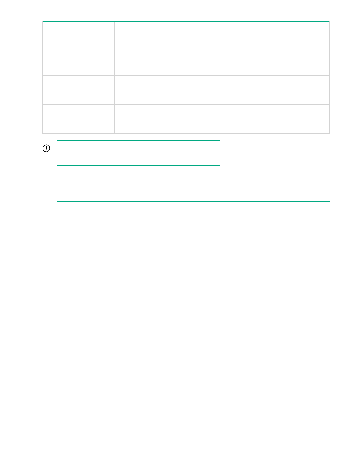
HPE StoreOnce 5100 mechanical and system components
HPE StoreOnce 3500 Series and HPE StoreOnce 5100 Systems are both based on the HPE ProLiant
DL380p server. For Mechanical and System components, see Figures 3 and 4. The following drawing shows
the rear view of the HPE StoreOnce 5100 System. It is also valid for the HPE StoreOnce 3500 Series, apart
from the two OS disks, which are only found in HPE StoreOnce 5100 Systems.
No
No
Yes
No
No
Figure 5: HPE StoreOnce 5100 System and HPE StoreOnce 3500 Series rear view
1 Slot 1, available for Optional Hardware 2 Slot 2, SAS expander card
3 Slot 3, RAID controller card 4 Slot 4, available for Optional Hardware
5 Slot 5, available for Optional Hardware 6 Slot 6, available for Optional Hardware
7 Optional serial port 8 OS drive 1 (not HPE StoreOnce 3500 Series)
9 OS drive 2 (not HPE StoreOnce 3500 Series) 10 Power supply 1 (PS1)
11 Power supply 2 (PS2) 12 Video connector
13 1Gb RJ45 Port 4 14 1Gb RJ45 Port 3
14 HPE StoreOnce 5100 mechanical and system components
Table Continued
Page 15

15 1Gb RJ45 Port 2 16 1Gb RJ45 Port 1 (eth0)
17 iLO4 connector 18 USB connectors
19 Rear UID LED
HPE StoreOnce 5100 System Capacity Upgrade Kit
Components
The HPE StoreOnce 5100 System (48 TB) Capacity Upgrade Kit (BB916A) is a 2U disk enclosure containing
twelve 4 TB disks. It includes a hot spare disk. The StoreOnce configuration has a single I/O module (in the
top location) plus a “blank” module.
The following table lists Spares Part Numbers for the main components in the storage enclosure.
NOTE:
This list is an offline list, created from partsurfer. If there is a problem with these Spares Part Numbers,
check the online source at: http://partsurfer.hpe.com/search.aspx. If the problem exists in the online
source, use the feedback form to log the problem: http://partsurfer.hpe.com/ContactUs.aspx.
Table 5: HPE StoreOnce Capacity Upgrade, BB916A
Part Spares Part Number Description Hot plug?
Enclosure backplane 832031-001* SPS-PCA Backplane LFF
HDD (1-based/IOM)
Hard disk cage 781531-001 SPS Cage; LFF Hard
Disk Drive (HDD)
Fan assembly 781532-001 SPS Fan Assembly Yes
I/O module 781867-001* SPS I/O Module; LFF 2
Port
Power distribution board 808276-001 SPS-VRM Assy No
Power supply 536404-001 SPS-PWR SUPPLY,
460W,12V,HTPLG,RED
Rail kit 700520-001 SPS-RAIL KIT 2U No
HDD, hard disk drive 844894-001 SPS-DRV HD 4TB 3.5
7.2K 6G SAS QR MDL
Fan control card cable 740127-001 SPS - Fan interconnect
cable
No*
No
No*
Yes
Yes
No
Table Continued
HPE StoreOnce 5100 System Capacity Upgrade Kit Components 15
Page 16
Part Spares Part Number Description Hot plug?
HP external 1 m (3 ft) HD
716195–B21 No
Mini-SAS x 4 to HD MiniSAS x 4 cable
supplied with the product
HP external 0.5 m (1.5 ft)
691970–001 No
HD Mini-SAS x 4 to HD
Mini-SAS x 4 cable
HP external 2 m (6 ft) HD
716197–B21 No
Mini-SAS x 4 to HD MiniSAS x 4 cable
IMPORTANT:
* Items are not hot-plug because there is only one I/O module.
NOTE:
A 1 meter SAS cable is supplied with the product. 0.5 meter and 2 meter cables may also be purchased.
Cables over 2 metes are not supported.
16 Finding part numbers for replacement parts
Page 17
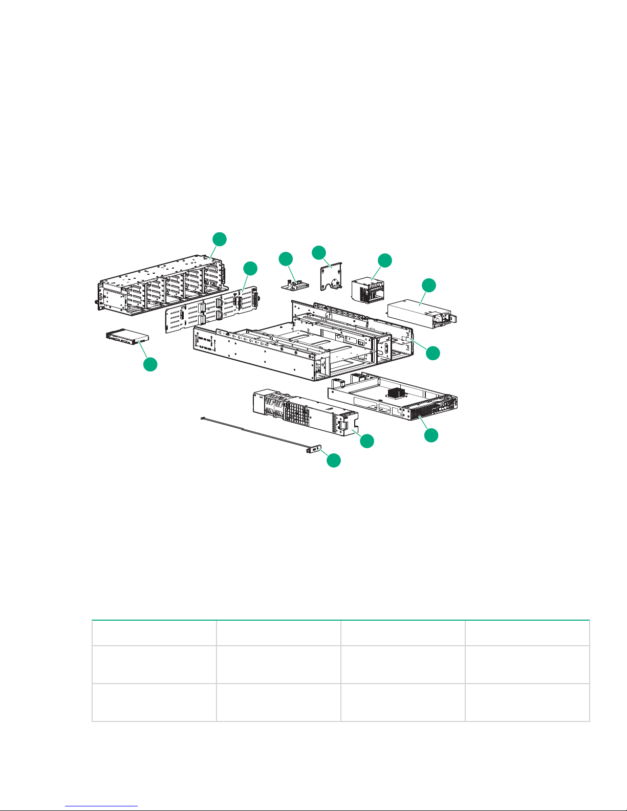
HPE StoreOnce 5100 System Capacity Upgrade System components
1
2
3
4
5
6
7
8
9
10
11
1 Drive cage 2 Backplane
3 Interface between fan and backplane 4 Airguard
5 Voltage Regulator (VRM) or power module 6 Power supply
7 Enclosure 8 I/O module
9 Fan module 10 Rear unit ID
11 Disk drive
Figure 6: HPE StoreOnce 5100 System Capacity Upgrade System components
Optional Hardware Components
All Optional Hardware PCIe cards and SFP transceivers that support connection to a 10GbE network and/or a
Fibre Channel SAN can be swapped like for like. The following table lists the part numbers for HPE
StoreOnce Optional Hardware. Optional Hardware is supported with the HPE StoreOnce 5100 System and
HPE StoreOnce 3500 Series. It is not supported with the HPE StoreOnce 3100 System.
Table 6: Optional Hardware Part Numbers
Description Part Part number Hot plug?
10GbE-T network card SPS-BD ETHERNET
10GB 2P 530T ADPTR
10GbE SFP network card SPS-PCA Ethernet 10Gb
2P 557 SFP-ADPTR
HPE StoreOnce 5100 System Capacity Upgrade System components 17
657128-001 No
792834-001 No
Table Continued
Page 18
Description Part Part number Hot plug?
10GbE SFP transceiver SPS-SFP+,10G BLc,SR 456096-001 Yes
8Gb FC card SPS-BD, HBA, 82q DP
489191-001 No
FC PCIe
8Gb FC transceiver SPS-SFP, 8GB, FC
468508-001 Yes
SHORT WAVE
16Gb FC card 16GB FC Card 699765-001 No
16Gb FC transceiver SPS-16Gb SFP+SW
793443-001 Yes
Industrial XCVR 1 Pack
IMPORTANT:
Providing the replacement card is of the same type and is installed in the same slot, no activation or
licensing is required.
18 Finding part numbers for replacement parts
Page 19

General precautions and safety guidelines
Required tools
The following items are required for some replacement procedures:
• T-8 Torx screwdriver
• T-10 Torx screwdriver
• T-15 Torx screwdriver
• Phillips screwdriver
Component replacement guidelines
CAUTION:
Removing a component significantly changes the air flow within the enclosure. Components must be
installed for the enclosure to cool properly. If a component fails, leave it in place in the enclosure until a
new component is available to install.
Use the following guidelines when replacing a component in the HPE StoreOnce System or the HPE
StoreOnce 5100 System Capacity Upgrade enclosure.
• Before replacing a component, verify its status to ensure that it needs replacement. To verify component
status, check the status LEDs, event logs, product-specific logs, and management utilities for component
health and location information.
• Parts can be damaged by electrostatic discharge. Keep parts in electrostatic containers until needed and
ensure you are properly grounded when touching static-sensitive components.
• HPE recommends waiting until periods of low storage system activity to replace a component.
• When replacing components at the rear of the rack, cabling might obstruct access to the component.
Carefully move any cables out of the way to avoid loosening any connections. In particular, avoid cable
damage that might be caused by:
◦ Kinking or bending.
◦ Disconnecting cables without capping. If uncapped, cable performance might be impaired by contact
with dust, metal, or other surfaces.
◦ Placing removed cables on the floor or other surfaces, where they might be walked on or otherwise
compressed.
Safety precautions
Retain and follow all product safety and operating instructions. Always refer to the documentation (printed or
electronic) supplied with your product. If there is a conflict between this document and the product
documentation, the product documentation takes precedence. To reduce the risk of bodily injury, electric
shock, fire, and damage to the equipment, observe all warnings on the product and in the operating
instructions.
General precautions
CAUTION:
The installation and maintenance of products must be carried out by qualified personnel.
General precautions and safety guidelines 19
Page 20
If the product sustains damage requiring service, disconnect the product from the AC electrical outlet and
refer servicing to an HPE authorized service provider. Examples of damage requiring service include:
• The power cord, extension cord, or plug has been damaged.
• Liquid has been spilled on the product or an object has fallen into the product.
• The product has been exposed to rain or water.
• The product has been dropped or damaged.
• The product does not operate normally when you follow the operating instructions.
To reduce the risk of personal injury or damage to the product:
• Place the product away from radiators, heat registers, stoves, amplifiers, or other products that produce
heat.
• Never use the product in a wet location.
• Avoid inserting foreign objects through openings in the product.
• Move products with casters carefully. Avoid quick stops and uneven surfaces.
Preventing electrostatic discharge
To prevent damaging the product, be aware of the precautions required when replacing the system or
handling parts. A discharge of static electricity from a finger or other conductor may damage system boards or
other static-sensitive devices. This type of damage may reduce the life expectancy of the device.
To prevent electrostatic damage:
• Avoid hand contact by transporting and storing products in static-safe containers.
• Keep electrostatic-sensitive parts in their containers until they arrive at static-free workstations.
• Place parts on a grounded surface before removing them from their containers.
• Avoid touching pins, leads, or circuitry.
• Always be properly grounded when touching a static-sensitive component or assembly.
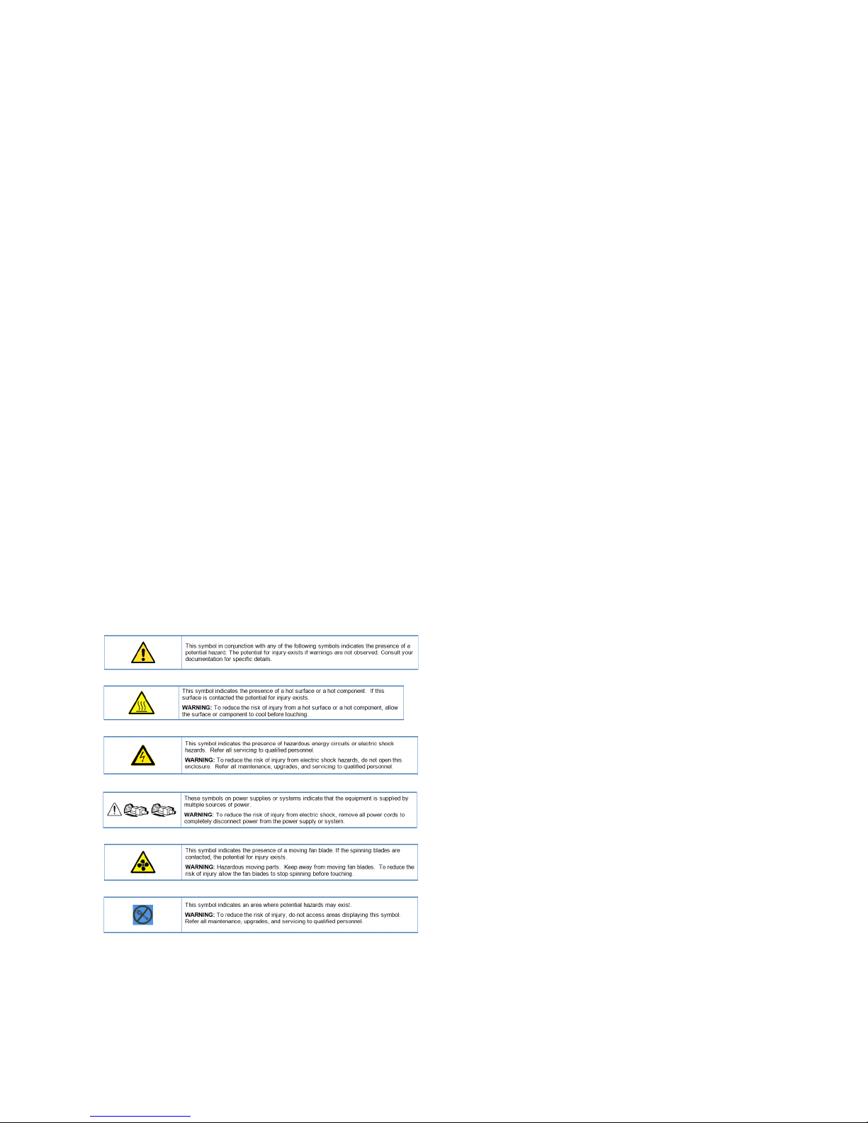
Equipment symbols
The following symbols may be placed on equipment to indicate the presence of potentially hazardous
conditions:
20 Preventing electrostatic discharge
Page 21
Identifying problems
POST messages and troubleshooting
The HPE StoreOnce Management Console (GUI and Command Line Interface) are the primary sources of
troubleshooting information. However, they do not capture power-on self-test hardware-related issues. Always
refer to the appropriate HPE ProLiant Gen9 Maintenance and Service Guide for Power-On Self-Test (POST)
information. To view POST messages, you will need a system console attached to the HPE StoreOnce
System.
Using the StoreOnce GUI to identify a problem
It is possible to configure recipients for SNMP traps or email alerts, as described in the StoreOnce System
User Guide for your product. These users will be notified of any problems with hardware components. You
can also use the StoreOnce GUI and StoreOnce CLI to identify problems and access alerts.
The following examples illustrate how problems with a hard disk can be identified.
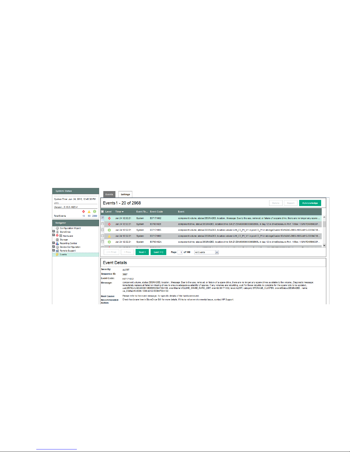
Alerts in the Events Log
Select Events. The alert is recorded in the Events window with Event Details at the bottom of the window.
Failed disk in the Hardware tree
The following example shows the Hardware tree expanded to show the disk failure in the expansion shelf.
Identifying problems 21
Page 22

Using the StoreOnce CLI to identify a problem
Overview
The following StoreOnce CLI commands can also be used to identify hardware problems and to navigate the
hardware tree for details about a specific component.
• hardware show problems
• hardware show status <Dev-id>
The following example illustrates how to use the StoreOnce CLI commands to find out more about the disk
problems we have identified on the StoreOnce GUI. See the HPE StoreOnce CLI Reference Guide for more
details.
Identifying a problem
Procedure
1. To display warnings for all hardware components, run the StoreOnce CLI command:
hardware show problems
The output of this command will assist you in identifying the storage cluster and component that is causing
a problem.
2. To drill down to the hardware component causing the problem run the StoreOnce CLI command,
hardware show status <Dev-id> iteratively, where <Dev-id> is the component with a DEGRADED
status until the required component is displayed (it will have a status of FAILED or MISSSING). For
example:
# hardware show status
Name Dev-id Status
-------------------- ------------------------------------ -------HPXXXNNNNNNS 37373937-3133-5A43-4A34-333530333553 DEGRADED
p1224 Storage System 051dbf3f-0000-1000-8017-533646303433 DEGRADED
# hardware show status 051dbf3f-0000-1000-8017-533646303433
Name Dev-id Status
-------------------- ------------------------------------ --------
22 Using the StoreOnce CLI to identify a problem
Page 23

p1224 Storage System 051dbf3f-0000-1000-8017-533646303433 DEGRADED
Drive Cage 5001438030123680 DEGRADED
Pools pools-1 DEGRADED
Controller 1 50014380266A0140 OK
# hardware show status 5001438030123680
Name Dev-id Status
----------------------- ---------------------- -------Drive Cage 5001438030123680 DEGRADED
Disk 5000C50076A2E72F 5000C50076A2E72F OK
Disk 5000C500768723A7 5000C500768723A7 OK
Disk 5000C500768AF62B 5000C500768AF62B OK
Disk 5000C5007689EC7B 5000C5007689EC7B OK
Disk 5000C50076A07ACB 5000C50076A07ACB OK
Disk 5000C5007687823F 5000C5007687823F OK
Disk 5000C50076A033DB 5000C50076A033DB OK
- Drive_Missing_b1000082 MISSING
Disk 5000C50076A0D1DB 5000C50076A0D1DB OK
Disk 5000C5007686F21F 5000C5007686F21F OK
Disk 5000C5007688B5BB 5000C5007688B5BB OK
Disk 5000C5007689C0A3 5000C5007689C0A3 OK
3. When you reach a faulty component, you can also use the StoreOnce CLI command to display details and
look at the diagnostic message for more information:
hardware show status <Dev-id> details
NOTE:
In the following example, we have truncated the output to highlight the information returned for the
missing disk.
# hardware show status 5001438030123680 details
Name
-----------------------------------------------------------Drive Cage
Dev-id = 5001438030123680
Status = DEGRADED
message = type = driveEnclosure
model = 12G SAS Exp Card
serialNumber = PDNRB0AZT6G0I5
firmwareVersion = location = Port: 1I Box: 1
Disk 5000C50076A2E72F
Dev-id = 5000C50076A2E72F
Status = OK
message = type = drive
model = MB4000FCWDK
serialNumber = S1Z0AN1R0000K45005X7
firmwareVersion = HPD5
location = Port: 1I Box: 1 Bay: 1
volumeName = LUN 1, LUN_Pool 1_V1
Identifying problems 23
Page 24

capacity = 4.00 TB
driveType = HDD
rpm = 7200
totalPowerOnHours = 5351
.....
.....
Dev-id = Drive_Missing_b1000082
Status = MISSING
message = The drive is missing or has failed.
type = drive
model = serialNumber = firmwareVersion = location = Port: 1I Box: 1 Bay: 8
volumeName = LUN_C3_P1_V1
capacity = 4.00 TB
driveType = Unknown
.....
.....
Disk 5000C5007689C0A3
Dev-id = 5000C5007689C0A3
Status = OK
message = type = drive
model = MB4000FCWDK
serialNumber = S1Z07ETP0000K447CUZY
firmwareVersion = HPD5
location = Port: 1I Box: 1 Bay: 12
volumeName = LUN_C3_P1_V1
capacity = 4.00 TB
driveType = HDD
rpm = 7200
totalPowerOnHours = 5350
4. After identifying the issue that requires correcting, follow the instructions in the relevant chapter of this
guide.
5. Be sure to check that all problems have been resolved. Rerun the StoreOnce CLI command:
hardware show problems
The output returned should now be blank.
LEDs and problem diagnosis
Server LEDs (all models)
24 LEDs and problem diagnosis
Page 25

Front panel LEDs
1
2
3
4
Figure 7: Front panel LEDs for HPE StoreOnce 3500 Series and HPE StoreOnce 5100 System
1 System health LED 2 Power LED and on/off button
3 NIC status LED 4 UID LED
Front panel LEDs and buttons behavior
Description Status
Health LED* Solid green = Normal
Flashing green (1 Hz/cycle per sec) = iLO is
rebooting
Flashing amber = System degraded
Flashing red (1 Hz/cycle per sec) = System critical**
Power-on/Standby button and system power LED* Solid green = System on
Flashing green (1 Hz/cycle per sec) = Performing
power-on sequence
Solid amber = System in standby
Off = No power present†
Table Continued
Front panel LEDs 25
Page 26

Description Status
3 4
1 2 3 4
NIC status LED* Solid green = Link to network
Flashing green (1 Hz/cycle per sec) = Network active
Off = No network activity
UID button/LED* Solid blue = Activated
Flashing blue:
• 1 Hz/cycle per sec = Remote management or
firmware upgrade in progress
• 4 Hz/cycle per sec = iLO manual reboot sequence
initiated
• 8 Hz/cycle per sec = iLO manual reboot sequence
in progress
Off = Deactivated
*When all four LEDs described in this table flash simultaneously, a power fault has occurred.
**If the health LED indicates a degraded or critical state, review the system IML or use iLO to review the
system health status.
†Facility power is not present, power cord is not attached, no power supplies are installed, power supply
failure has occurred, or the power button cable is disconnected.
Figure 8: Front panel LEDs, HPE StoreOnce 3100 System
1 UID LED 2 NIC status LED
3 System health LED 4 Power LED and on/off button
26 Identifying problems
Page 27

Disk drive LEDs
Figure 9: Disk drive LEDs (in servers)
1. Drive locate LED Solid blue = The drive is being identified by a host
2. Disk activity ring LED Off = No drive activity
3. Do not remove LED Solid white = Do not remove the drive. Removing the drive
application.
Flashing blue = The drive carrier firmware is being updated
or requires an update.
Rotating green = Drive activity
causes one or more of the logical drives to fail.
Off = Removing the drive will not cause a logical drive to fail.
4. Drive status LED Off = The drive is not configured by a RAID controller.
Solid green = The drive is a member of one or more logical
drives.
Flashing green = The drive is rebuilding or performing a
RAID migration, stripe size migration, capacity expansion, or
logical drive extension.
Flashing amber/green = The drive is a member of one or
more logical drives and predicts the hard drive will fail.
Flashing amber = The drive is not configured and predicts
the hard drive will fail.
Solid amber = The drive has failed
Disk drive LEDs 27
Page 28

Rear panel LEDs
1 2 3 4 5
1
2
3
4
1
5
6
4
4
1
iLO
PS2
PS1 PS1
1
2 3
4 5
Figure 10: Rear panel LEDs, HPE StoreOnce 3100 System
Figure 11: Rear panel LEDs for HPE StoreOnce 3500 Series and HPE StoreOnce 5100 System
Table 7: Rear panel LED behavior
Item Description Status
1 UID LED Off = Deactivated
Solid blue = Activated
Flashing blue = System being
managed remotely
2 iLO4 LED Right = iLO link LED
Left = iLO activity LED
3R NIC link LED Off = No network link
Green = Network link
3L NIC activity LED Off = No network activity
Solid green = Link to network
Flashing green = Network activity
Table Continued
28 Rear panel LEDs
Page 29

Item Description Status
3 4
1
2
4 Power supply 2 LED
(optional on HPE 3100)
5 Power supply 1 LED Off = System is off or power supply
Off = System is off or power supply
has failed.
Solid green = Normal
has failed.
Solid green = Normal
Storage enclosure LEDs (HPE StoreOnce 5100 System only)
Front View LEDs
Figure 12: Capacity Upgrade front view
1. Disk drive UID 2. Disk drive status LED
3. System status LED 4. System locate UID button
Front panel system status LEDs
NOTE:
These indicators are also on the rear panel directly above power supply 2.
Table 8: Front panel system status LEDs
Indicator Display Description
System status LED Green on Normal operation
Amber on Critical fault.
Amber flashing Noncritical fault.
Locate UID Off Normal operation
Table Continued
Storage enclosure LEDs (HPE StoreOnce 5100 System only) 29
Page 30

Indicator Display Description
1 2 3 154 6 7 8 92 10 11
Blue on Location requested. Safe to power
off.
Blue flashing Location requested. Do not power
off. Indicates that maintenance is
in progress. For example, firmware
updating.
Disk drive LEDs
Table 9: Disk drive status LEDs
Indicator Display Description
Status LED Green on, amber off No fault, no I/O
Green flashing, amber on No fault, active I/O
Green off, amber on Fault
Green on, amber flashing Predictive fault, no I/O
Locate UID Off Normal operation
Rear view LEDs
Green flashing, amber flashing Predictive fault, active I/O
Blue on Location requested. Safe to
remove.
Blue flashing Location requested. Do not
remove. Indicates that
maintenance is in progress. For
example, firmware updating.
Figure 13: Capacity Upgrade rear view
30 Rear view LEDs
Page 31

1. Fan locate UID 2. Fan status LED
3. Pullout tab with serial number label 4. I/O module status LED
5. I/O module locate UID 6. Data ports
7. Data port status LEDs 8. Seven-segment display
9. System locate UID button 10. System status LED
11. Power supply status LED
Power supply LEDs
Table 10: Power supply module status LED
Indicator Display Description
Status LED Green on Normal operation
Amber on Fault
Amber flashing Predictive fault or nonoptimal
performance
Fan LEDs
Table 11: Fan module status LEDs
Indicator Display Description
Status LED Green on Normal operation
Amber on Fault
Amber flashing Predictive fault or nonoptimal
performance
Locate UID Off Normal operation
Blue on Location requested. Safe to
remove.
Blue flashing Location requested. Do not
remove.
I/O module LEDs
The following LEDs and indicators are used to verify disk enclosure I/O module operation.
Identifying problems 31
Page 32

Table 12: I/O module status LEDs
Indicator Display Description
7–segment display On Indicates the enclosure number or
an error/warning code
Data ports (DP-1, DP-2) Green on, amber off Link at high speed with no activity
Green flashing, amber off Link at high speed with activity
Green on, amber on Link at low speed with no activity
Green flashing, amber on Link at low speed with activity
Green off, amber on No link or no cable connected
Green flashing, amber flashing Location requested
I/O module status LED Green on, amber off Normal operation
Green flashing, amber off Shutdown in progress, no fault
Green off, amber on Fault
Green flashing, amber on Shutdown in progress, fault
Green on, amber flashing Predictive failure
Green flashing, amber flashing Shutdown in progress, predictive
failure
Locate UID Off Normal operation
Blue on Location requested. Safe to
remove.
Blue flashing Location requested. Do not
remove. Indicates that
maintenance is in progress. For
example, firmware updating.
HPE StoreOnce 5100 System expansion shelf error messages
Most error messages are reported in the StoreOnce GUI or CLI with appropriate diagnostic messages.
However, there are a few instances where problems are not explicitly recorded and it is necessary to check
the 7-segment display on the rear of the expansion shelf to identify the error code. Press the System Locate
UID button to display the error code.
This section contains a full list of error conditions.
32 HPE StoreOnce 5100 System expansion shelf error messages
Page 33

I/O module errors
Error code Error detail Recommended action
A3 Error in Expander
communication
A9 Permanent error in ESP
NVRAM I2C Bus
AE Permanent error in
Backplane I2C Bus
B3 Expander using default SAS
address
BD Error in ESP communication
BF System identification value is
not available
I/O module firmware errors
Error code Error detail Recommended action
B8 Expander firmware image
error
BE Expander firmware version
mismatch with ESP firmware
version in own I/O module
1. Remove the module, wait 10 seconds, reinsert the
module.
2. If the error persists, then check for new firmware releases
and upgrade the enclosure firmware. New firmware
versions, containing new features and defect fixes, are
released periodically.
3. If the error persists, contact a Hewlett Packard Enterprise
representative. An I/O module replacement may be
necessary.
1. Update the firmware of the I/O module that displays the
error and wait until it restarts.
2. Then update the firmware of the other I/O module and
wait until it restarts.
SAS cable error
Error code Error detail Recommended action
B9 SAS cable hardware error 1. Verify the SAS cable status indicators. For the cables with
an amber LED (error), check if the cables are properly
connected in both sides.
2. If the cables are properly connected and the error
persists, replace the cables.
3. If replacing the cables does not resolve the issue, then
check for new firmware releases. A firmware upgrade
might fix the issue.
4. If there is no new firmware available, or upgrading the
firmware is not possible, contact a Hewlett Packard
Enterprise representative. An I/O module replacement
may be necessary.
I/O module errors 33
Page 34

Thermal control errors
Error code Error detail Recommended action
C1 Permanent error in
temperature sensor I2C bus
C2 Error reading data from
temperature sensor
Thermal shutdown alarms
Error code Error detail Recommended action
C3 Warning temperature
reached in temperature
sensor
C4 Critical temperature reached
in temperature sensor
C5 Minimum temperature
reached in temperature
sensor
1. Remove the module, wait 10 seconds, reinsert the
module.
2. If the error persists, then check for new firmware releases
and upgrade the enclosure firmware. New firmware
versions, containing new features and defect fixes, are
released periodically.
3. If the error persists, contact a Hewlett Packard Enterprise
representative. An I/O module replacement may be
necessary.
Check for thermal issues, such as extremely hot drives, air
blockages, missing or failed fans, or high ambient
temperature.
C6 Fans commanded to
maximum speed
C7 System shutdown because of
over temperature
Power supply module errors
Error code Error detail Recommended action
D2 Absence of the Power Supply
module 1
D3 Absence of the Power Supply
module 2
D9 Error in system voltage If a power supply module does not have a green LED
• Verify that the power supply is tightly inserted in the slot.
• If a power supply is missing, insert a module in the empty
slot and connect it to a power source.
illuminated, verify that it is correctly cabled to a power
source.
NOTE:
Table Continued
34 Thermal control errors
Page 35

Error code Error detail Recommended action
DA Input power loss in Power
Supply module 1
DB Input power loss in Power
Supply module 2
Power supply communication errors
Error code Error detail Recommended action
D4 Permanent error in Power
Supply modules
D5 Communication error with
Power Supply module 1
D6 Communication error with
Power Supply module 2
This warning can also be caused by a failed power
supply.
1. If cabling was not the root cause, troubleshoot by
reinserting each power supply in turn.
2. If the error persists, check for new firmware releases and
upgrade the enclosure firmware. New firmware versions,
containing new features and defect fixes, are released
periodically.
3. If the error persists, contact a Hewlett Packard Enterprise
representative. A power supply replacement may be
necessary.
1. Remove and reinsert each power supply in turn.
2. If the error persists, check for new firmware releases and
upgrade the enclosure firmware. New firmware versions,
containing new features and defect fixes, are released
periodically.
3. If the error persists, contact a Hewlett Packard Enterprise
representative. A power supply replacement may be
necessary.
Fan module errors
Error code Error detail Recommended action
E2 Absence of the Fan module 1 • Verify that the fan module is tightly inserted in the slot.
E3 Absence of the Fan module 2
E9 Failure in one or more rotors
EA Failure in one or more rotors
of Fan module 1
of Fan module 2
• If a fan module is missing, insert a module in the empty
slot.
1. If a fan module has an amber LED indication, try
reinserting it.
2. If none of the fans have an amber LED, replace one fan
module and wait 30 seconds.
3. If the error persists, check for new firmware releases and
upgrade the enclosure firmware. New firmware versions,
containing new features and defect fixes, are released
periodically.
4. If the error persists, contact a Hewlett Packard Enterprise
representative. A power supply replacement may be
necessary.
Power supply communication errors 35
Page 36

Powering on and off, firmware upgrades, and
other processes
Preparing for StoreOnce maintenance
Many of the maintenance procedures described in this guide require the system to be powered off. Advise
users of the Maintenance window when the HPE StoreOnce System will be unavailable and use the
StoreOnce GUI or CLI to power off cleanly and then disconnect the system from the power supply.
It is best practice to save the system configuration before carrying out maintenance activities. Use the
StoreOnce CLI command:
config save devices
If you also have the Security Pack license installed and have applied encryption to any VTL libraries, NAS
shares or Catalyst stores, ensure that the latest keystore has been saved. Use the StoreOnce CLI command:
config save keystore
See the StoreOnce CLI Reference Guide at http://www.hpe.com/info/storeonce/docs for more details
about these commands.
Requirements for powering on and off
To power off
If the maintenance activity requires you to power down the system:
• StoreOnce GUI:
Select Maintenance from the Navigator and click Shutdown.
• StoreOnce CLI:
Use the StoreOnce CLI command system shutdown.
HPE StoreOnce 5100 System only: Any storage enclosure attached to the head server is automatically
powered off at the same time. Storage enclosures do not have separate power-on buttons and must be
unplugged from the power supply before carrying out maintenance activities.
To power on
HPE StoreOnce 5100 System only: Reconnect all storage enclosures to the power supply first. They are
automatically powered on. Allow the power-on to complete before powering on the head server; wait for the
LEDs to show solid green.
To power on the appliance, press the power-on button on the HPE StoreOnce System.
HPE StoreOnce Remote Support
HPE StoreOnce Remote Support uses STaTS to send remote event notifications from the StoreOnce System
to HPE Support. If you have configured HPE StoreOnce Remote Support for use on your system, run the
following StoreOnce CLI command before commencing the maintenance activity to suppress remote event
reporting.
system enable remoteeventsuppression "XYZ Maintenance"
This prevents a support case being generated during the maintenance task.
To return to normal mode after maintenance, run the StoreOnce CLI command:
36 Powering on and off, firmware upgrades, and other processes
Page 37

system disable remoteeventsuppression "XYZ Maintenance"
Upgrading BIOS or hardware firmware components
Do not upgrade BIOS or hardware firmware components individually using downloads from the HPE Support
website because currently supported firmware component updates are already embedded within the
StoreOnce software. Always use the StoreOnce CLI or the StoreOnce GUI to implement BIOS and hardware
firmware component checks and updates.
Updating firmware using the StoreOnce GUI
Procedure
1. Select Firmware to view the firmware versions for hardware components, and to update firmware versions
if required.
The Firmware window appears with the following tabs:
• Server: Contains firmware details for all server components.
• Storage: Contains firmware details for all storage components.
2. To perform a check on the currently installed firmware versions for all components, click Scan.
This action will populate the firmware tabs and may take several minutes to run.
NOTE:
If a firmware update is already in progress, the scan will fail.
After running a Scan, the Recommended Action field in the component list is updated to show whether
individual components require an upgrade or a downgrade. Components requiring an upgrade are
automatically selected. Components requiring a downgrade are not automatically selected. A downgrade
takes longer to complete and is optional for some components, such as hard drives. It may be carried out
separately, if required, after the upgrade has completed.
NOTE:
When the firmware updates are initiated, the backup devices will be taken offline. Before performing
this step, check that there are no outstanding backup jobs pending.
IMPORTANT:
Do not shutdown or reboot your system or any system component until the final step. Special
instructions may apply.
3. Click Update Selected or Update All. (Update All will attempt to update all components that are in the
state where there is an update recommended; it will not try to update components that do not need an
update.)
The Status field will show which components are being updated and which updates have been completed
In some cases, when the firmware update has been loaded, you will need to perform a reboot to complete
the firmware update. If a reboot is required, a pop-up message will appear on your GUI screen after
loading is completed. The message will also advise what type of reboot is required.
If a software reboot is needed, you will see a message asking if you want to reboot your system now or
later. If you click Yes, your system will be rebooted.
A power cycle, or cold reboot, requires that the system must be shut down for at least 60 seconds before
powering on using the Power-On buttons on the appliance.
Upgrading BIOS or hardware firmware components 37
Page 38

Updating firmware using the StoreOnce CLI
Procedure
1. To show the status of firmware, run the StoreOnce CLI command:
# hardware show firmware <node|storage|all>
2. To see if any firmware needs upgrading, check the Action column.
IMPORTANT:
Do not shut down or reboot your system or any system component until the final step. Special
instructions may apply.
3. Use the hardware update firmware command, as required. For example, there may be instances
where replacement hardware may need a firmware downgrade to bring it in line with the supported
firmware version of the installed StoreOnce software on the system being maintained. (Use the force
parameter in the command to enable this action.)
The command syntax is:
hardware update firmware <node|storage|all>
The command will be applied across all server components or across all storage components. The all
parameter updates all firmware components across all components.
There may be instances where replacement hardware may need a firmware downgrade to bring it in line
with the supported firmware version of the installed StoreOnce software on the system being maintained.
Use the force parameter in the command to enable this, but be aware that the update will take longer to
complete.
4. In some cases, when the firmware update has been loaded, you will need to perform a reboot to complete
the firmware update. If a reboot is required, a pop-up message will appear on your GUI screen after
loading is completed. The message will also advise what type of reboot is required.
a. Reboot the system using the StoreOnce CLI command:
system reboot
b. Power down the nodes using the StoreOnce CLI command:
system shutdown
After the system has completely shutdown, wait at least 60 seconds before powering on using the
Power-On buttons on the appliance.
Upgrading StoreOnce software
To establish which StoreOnce software version is installed, click on StoreOnce in the Navigator and look at
the Software Revision under System Information.
To find out if a later software release is available, check HPE Support at http://www.hpe.com/support/
softwaredepot. If it is, download the software release and follow the instructions in the accompanying
Release Notes to install the software.
Supported web browsers for the StoreOnce Management GUI
• Internet Explorer 9, 10 and 11 (note that Internet Explorer 8 is not supported and some StoreOnce features
will not work)
• Mozilla Firefox v23 and above and Firefox ESR24
Refer to www.hpe.com/storage/spock for the latest information about which browser versions are
supported.
38 Updating firmware using the StoreOnce CLI
Page 39

Running a system self test
The StoreOnce CLI command, system confidencechecker, runs a self-test on the system and produces
a report of any problems. It is good practice to run this command before and after maintenance activities.
Refer to the HPE StoreOnce System CLI Reference Guide for more information about using this command.
system confidencechecker runtest all
Confidence checks running. Checks will take maximum of 60 seconds. Please
wait...
###############################################################################
# #
# CONFIDENCE REPORT #
# #
###############################################################################
Report Date: Wed Nov 18 11:55:40 UTC 2015
Product ID: HPE StoreOnce 3540 System
Cluster S/N: XXXXXNNNNNNXX
Version: 3.14.0-1539.3
Test Type: all
### FILE SYSTEM REPORT ########################################################
File System Check:
[RESULT]
PASSED
### INTERNAL NETWORK REPORT ###################################################
Internal Network Check is supported only on HP StoreOnce multinode products.
### EXTERNAL NETWORK REPORT ###################################################
External Network Check:
[RESULT]
PASSED
### SAS CONFIGURATION REPORT ##################################################
Sas Configuration Check is supported only on HP StoreOnce multinode, 5500 and
4900 backup products.
### NOTE ######################################################################
For any warning or error messages in this report, please consult the
troubleshooting
section in the customer user guide and follow the steps to perform corrective
Running a system self test 39
Page 40

action.
### END #######################################################################
Command Successful
HPresetpassword account
The purpose of the HPresetpassword account
The HPresetpassword account provides a method for the local Admin user to recover the Admin password
back to a default state.
• username = HPresetpassword
• default password = hpresetpassword
Best practice is to change the default password after installation.
This user account does not provide any access to StoreOnce functions or data that may already be on the
system.
Changing the password for the HPresetpassword account
Procedure
1. Gain access to the local system console either using a locally attached USB keyboard and monitor or via
2. At the Login prompt, type the username (HPresetpassword) and default password (hpresetpassword):
3. A list of available commands will be presented.
4. Run the command manage to change the password for the HPresetpassword user. At the prompts,
5. Type exit to log out.
6. Store the new password securely in an offline Password Security tool.
the iLO remote console.
NOTE:
This account is not accessible via a remote ssh session.
• reset: Reset the 'Admin' password to 'admin'
• manage: Change the 'HPresetpassword' user's password
• help: List available commands
• exit: Log out
provide:
a. (current) UNIX password: the default at installation is hpresetpassword.
b. New UNIX password: the new password must be strong and memorable. If it is weak, for example a
dictionary name, it will not be accepted.
c. Retype new UNIX password: re-enter the new password to confirm it
Resetting the password for the local Admin user
Procedure
1. Gain access to the local system console either using a locally attached USB keyboard and Monitor or via
iLO remote console.
2. At the Login prompt type: HPresetpassword
40 HPresetpassword account
Page 41

3. When prompted for the password enter the current password. The default is hpresetpassword, but if you
are following best practices you will have changed this Password after installation.
4. Once logged in a list of available commands will be presented.
5. Type reset; this will immediately reset the default password of the Admin user to admin.
6. Type exit to log out.
Powering on and off, firmware upgrades, and other processes 41
Page 42

Replacing the StoreOnce System motherboard
Motherboard replacement tasks specific to HPE StoreOnce
Systems
This chapter highlights the information that is specific to HPE StoreOnce Systems. For detailed, step-by-step
instructions on replacing the motherboard, refer also to the appropriate HPE ProLiant Maintenance and
Service Guide.
IMPORTANT:
If the status of the cache module on the failed motherboard is OK, transfer it to the replacement
motherboard. When replacing the motherboard make sure that all items on the old motherboard are
reinstalled on the replacement motherboard, for example the SAS cables that connect to the internal
disks in the server.
This chapter describes the following activities that are specific to HPE StoreOnce Systems:
• If possible, obtain iLO4 license details and review the StoreOnce PCIe card configuration, DIMM
configuration, and SAS cabling before removing the motherboard. These components must be replaced in
the same locations after replacing the motherboard.
• After replacing the motherboard and restoring internal components to their correct locations, reconfigure
BIOS settings and iLO 4 settings during boot up.
• Review and update firmware, if necessary.
• After power up, rewrite warranty serial numbers into BIOS.
CAUTION:
To reduce the risk of personal injury or damage to the equipment, consult the safety information and
user documentation provided with the server and system motherboard before replacing the
motherboard.
Identifying the Activation Key for the iLO4 license
All products are shipped with paper copies of the iLO4 licenses. If you no longer have these licenses and the
board is still working for the iLO4 GUI connection via its management Ethernet port, make a note of the
license before you remove the motherboard. (If it is not working, contact HPE Support.)
Procedure
1. Log on to the iLO4 GUI.
2. Select the Administration Tab.
3. Select Licensing and make a note of the Activation Key.
Before replacing the motherboard—component
configuration
Before replacing the motherboard, make a note of PCIe slot allocation and SAS cabling.
• HPE StoreOnce 3100 System: Only one PCIe slot is used, slot 1 for the RAID controller card.
• HPE StoreOnce 3500 Series and HPE StoreOnce 5100 System: This system supports Optional Hardware.
Slots 2 and 3 are always used for the SAS expander card and the RAID controller card, respectively, but
42 Replacing the StoreOnce System motherboard
Page 43

the remaining four slots may be configured with 10GbE network and/or Fibre Channel cards. Make a note
1 2 3 4 5 6 7 8 9 1011 12
Ch 3
Ch 4 Ch 2 Ch 1
C G K D H L J F B I E A
P2
1 2 3 4 5 6 7 8 9 1011 12
Ch 3
Ch 4 Ch 2 Ch 1
C G K D H L J F B I EP1A
of the configuration and be sure to reinstall the cards in the exact same slots.
• HPE StoreOnce 5100 System only: If Capacity Upgrade Kits are connected, make a note of the first in the
daisy chain sequence. The cabling must be reconnected from the SAS controller card to the correct
Capacity Upgrade Kit for the server.
Motherboard spares part number and System Maintenance
switch
The motherboard for the HPE StoreOnce 3100 System, HPE StoreOnce 3500, and 5100 System is the
standard DL360/DL380 Gen9 motherboard, spares part number 775400-001.
See the DL360p Gen 9 Maintenance and Service Guide and DL380p Gen 9 Maintenance and Service Guide
for more information about replacing the motherboard.
IMPORTANT:
There is a default boot mode setting on the system maintenance switch on the motherboard, which must
be set to Legacy and not be UEFI mode enabled (the BIOS/RBSU boot mode setting is also set to
Legacy).
The following drawing shows a ProLiant DL380 motherboard; the location of the System Maintenance switch
is the same for the ProLiant DL360 motherboard. The default value for all positions on the System
Maintenance switch is OFF. The S7 position must be set to ON for HPE StoreOnce systems.
Figure 14: Location of the system maintenance switch
DIMM locations
DIMM slots are numbered sequentially (1 to 12) for each processor. The supported AMP modes use the letter
assignments for population guidelines.
Motherboard spares part number and System Maintenance switch 43
Page 44
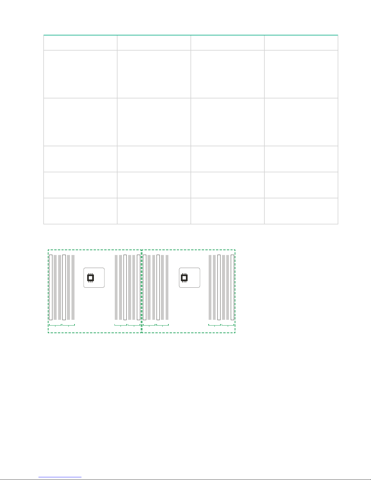
Table 13: DIMM slot locations
129
D
Ch 3 Ch 4
C
41
D
Ch 3 Ch 4
C41AB
Ch 2 Ch 1
129
AB
Ch 2 Ch 1
P2 P1
Model Processor DIMM Slots
HPE StoreOnce 5100
System
HPE StoreOnce 3500
Series
HPE StoreOnce 3100
System
1 DIMM 1
DIMM 2
DIMM 3
DIMM 4
2 DIMM 1
DIMM 2
DIMM 3
DIMM 4
1 DIMM 1
DIMM 2
2 DIMM 1
DIMM 2
1 DIMM 1
DIMM 2
Ch1, slot 12, A
Ch2, slot 9, B
Ch3, slot 1, C
Ch4, slot 4, D
Ch1, slot 12, A
Ch2, slot 9, B
Ch3, slot 1, C
Ch4, slot 4, D
Ch1, slot 12, A
Ch2, slot 9, B
Ch1, slot 12, A
Ch2, slot 9, B
Ch1, slot 12, A
Ch2, slot 9, B
The locations of DIMM slots are also shown on the StoreOnce hood label inside the server.
Figure 15: DIMM locations for HPE StoreOnce 5100 System
44 Replacing the StoreOnce System motherboard
Page 45

129
AB
Ch 2 Ch 1
129
AB
Ch 2 Ch 1
P2 P1
Figure 16: DIMM locations for HPE StoreOnce 3500 Series
129
AB
Ch 2 Ch 1
P2
not used
P1
Figure 17: DIMM locations for HPE StoreOnce 3100 System
After replacing the motherboard—BIOS and iLO
configuration
Configure the RBSU (ROM-Based Setup Utility) settings BEFORE connecting the FC, network, and SAS
cables to the server and BEFORE the system boots into the StoreOnce software, that is, during the server
POST sequence.
For all products you must:
Procedure
1. Boot up the StoreOnce System and watch the local console; the iLO4 IP addresses are shown (IPv4 and
IPv6).
NOTE:
If the iLO port is plugged into a network that provides DHCP, the acquired addresses will be shown
here and you can connect to the network address in a web browser to configure iLO. If not, you can
edit iLO4 during bootup as described later in this procedure.
After replacing the motherboard—BIOS and iLO configuration 45
Page 46

2. To access System Utilities, press F9 in the ProLiant POST screen. Select System Configuration
3. Select BIOS/Platform Configuration (RBSU) — System Options.
46 Replacing the StoreOnce System motherboard
Page 47

4. Change the RBSU settings, as shown in the tables in the next section.
5. Press F10 to save. Then press ESC until the System Utilities menu is displayed.
6. At this point, you can either press ESC to exit System Utilities and continue with the system reboot.
7. Or, if there are no DHCP–assigned IP addresses, you can manually configure iLO using the local
console. Select System Configuration.
8. Select the iLO 4 Configuration Utility.
Replacing the StoreOnce System motherboard 47
Page 48
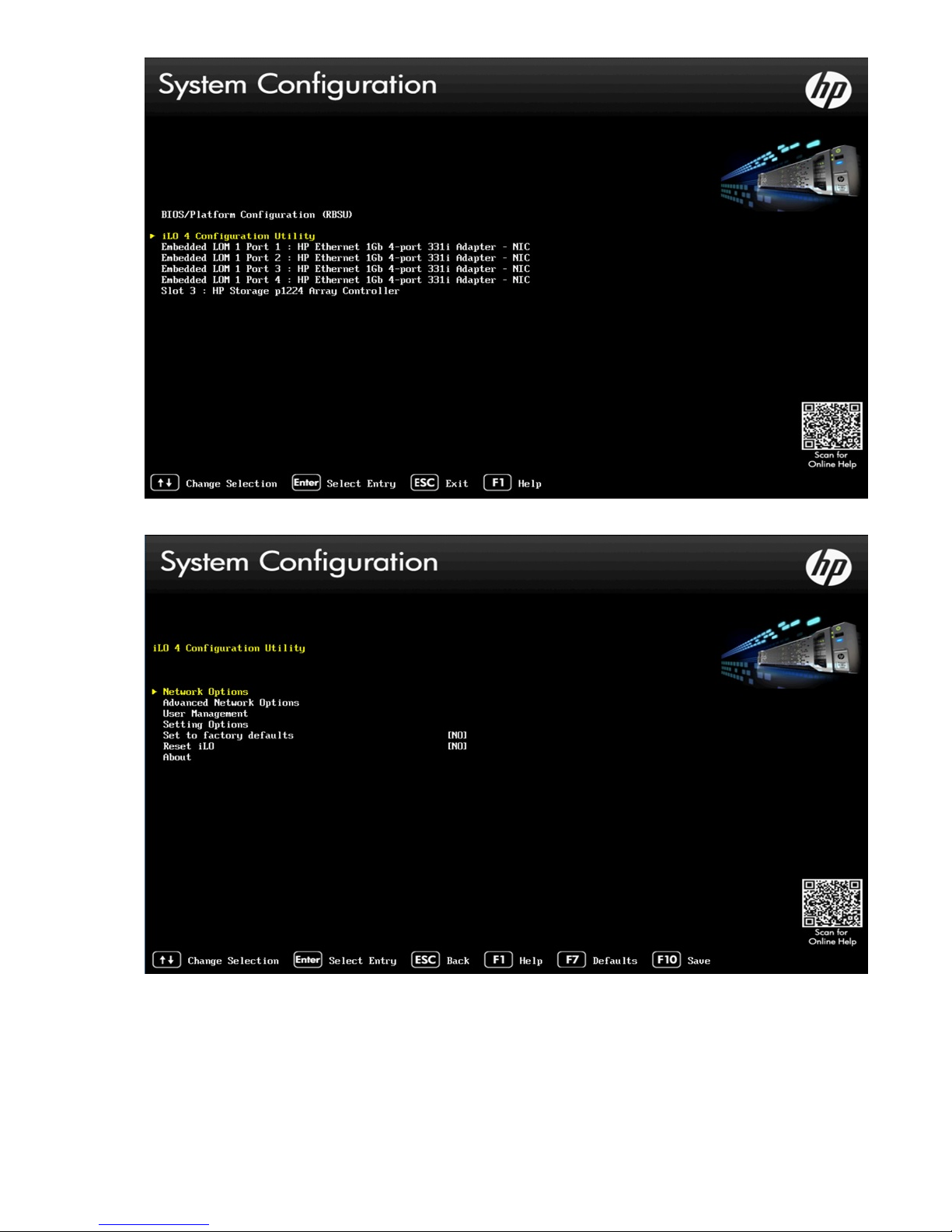
9. Select Network Options.
10. Configure your network settings and press F10 to save.
11. Press ESC until you exit System Utilities and can continue with the system reboot.
12. Check that an existing iLO4 Advanced license is loaded. If it is not, add it:
48 Replacing the StoreOnce System motherboard
Page 49

a. Log on to the iLO4 GUI.
b. Select the Administration Tab.
c. Select Licensing and enter the recorded license key in the section marked Enter License Activation
Key.
13. Use the StoreOnce GUI or StoreOnce CLI to check that the firmware on the new component is correct.
NOTE:
Note the output after running firmware upgrade. It will advise if you need a system reboot or a cold
reboot to install the new firmware revision successfully.
14. After power-up, it is necessary to rewrite warranty serial numbers into BIOS. Contact HPE Support for
assistance in rewriting warranty serial numbers.
RBSU settings
Table 14: RBSU settings for HPE StoreOnce 3100 System
Top menu item Sub menu 1 Sub menu 2 Current default
state
Boot options Boot Mode UEFI Mode Legacy BIOS mode
Power Management
Options
Advanced Options Advanced System
Date and Time Time (hh:mm:ss) As appropriate
BIOS Serial
Console and EMS
USB Options Embedded User
HP Power Profile Balanced Power
and Performance
Product ID 794750-B21
ROM Option
Thermal
configuration
Time zone UTC-07:00,
BIOS Serial
Console Port
Partition
Optimal Cooling Increased cooling
Mountain Time (US
& Canada)
Auto Physical
Disabled Only if 'enabled' in
Change to–
Maximum
performance
As appropriate
the first place
RBSU settings 49
Page 50

Table 15: RBSU settings for HPE StoreOnce 3500 Series and HPE StoreOnce 5100
System
Top menu item Sub menu 1 Sub menu 2 Current default
state
Boot options Boot Mode UEFI Mode Legacy BIOS mode
Power Management
Options
Performance
Options
Advanced Options Advanced System
Date and Time Time (hh:mm:ss) As appropriate
HP Power Profile Balanced Power
and Performance
Advanced
Performance
Tuning Options
ROM Option
Thermal
configuration
Node interleaving Disabled Enabled - i.e Turn
Product ID HPE 3520: 794751-
Optimal Cooling Increased cooling
Change to...
Maximum
performance
off NUMA for the
OS
B21
HPE 3540: 797731B21
HPE 5100: 794752B21
BIOS Serial
Console and EMS
USB Options Embedded User
iLO4 settings
Select the DNS/DHCP option and toggle DHCP Enable to OFF.
If DHCP is set to OFF, select NIC and TCP/IP and configure the network static IP addresses
Time zone UTC-07:00,
Mountain Time (US
& Canada)
BIOS Serial
Console Port
Partition
Auto Physical
Disabled Only if 'enabled' in
As appropriate
the first place
50 iLO4 settings
Page 51
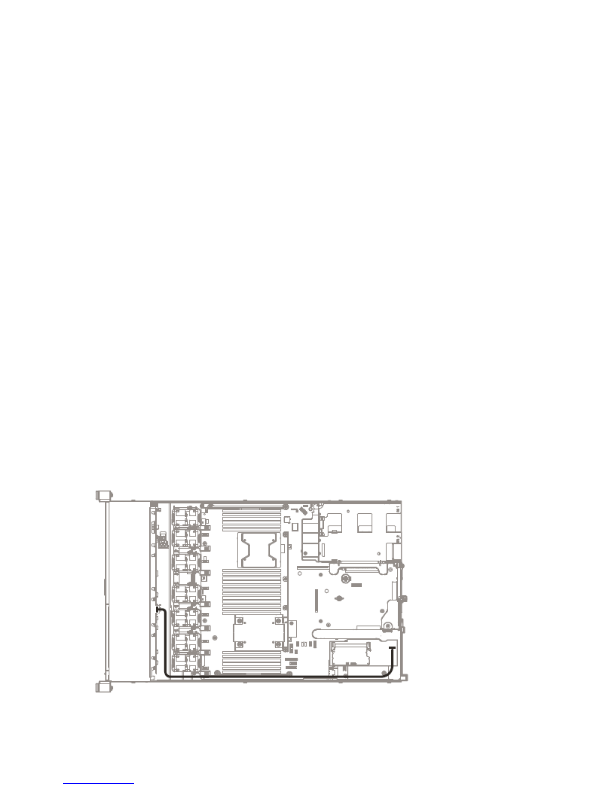
Replacing the p1224 RAID controller and
components
RAID controller component overview
All HPE StoreOnce Systems described within this guide use the p1224 RAID controller fitted with a RAID
cache module and SuperCapacitor. Each model has a single RAID controller.
The RAID cache module is seated on the RAID card and has one port to connect to the SuperCapacitor
(which is located in the center of the unit, clipped to the floor of the chassis behind the disk cage).
HPE StoreOnce 3500 Series and HPE StoreOnce 5100 System also have a SAS Expander card.
NOTE:
The locations of RAID cards and the internal SAS cabling configuration are also shown on the
StoreOnce hood label inside the server.
Part numbers
Replacement spares part numbers for the p1224 card, SuperCapacitor module, and SAS expander card are
as follows:
• HP p1224 RAID controller with 1GB cache module: 842475-001 (minimum firmware revision = 2.50)
• SuperCapacitor: 660093-001
• SAS expander card (not used with HPE StoreOnce 3100 System): 761879-001
For information about the part numbers for replacement internal SAS cables, see Internal SAS cabling on
page 51.
Internal SAS cabling
HPE StoreOnce 3100 System internal SAS cabling
Figure 18: Internal SAS cabling for HPE StoreOnce 3100 System
Replacing the p1224 RAID controller and components 51
Page 52
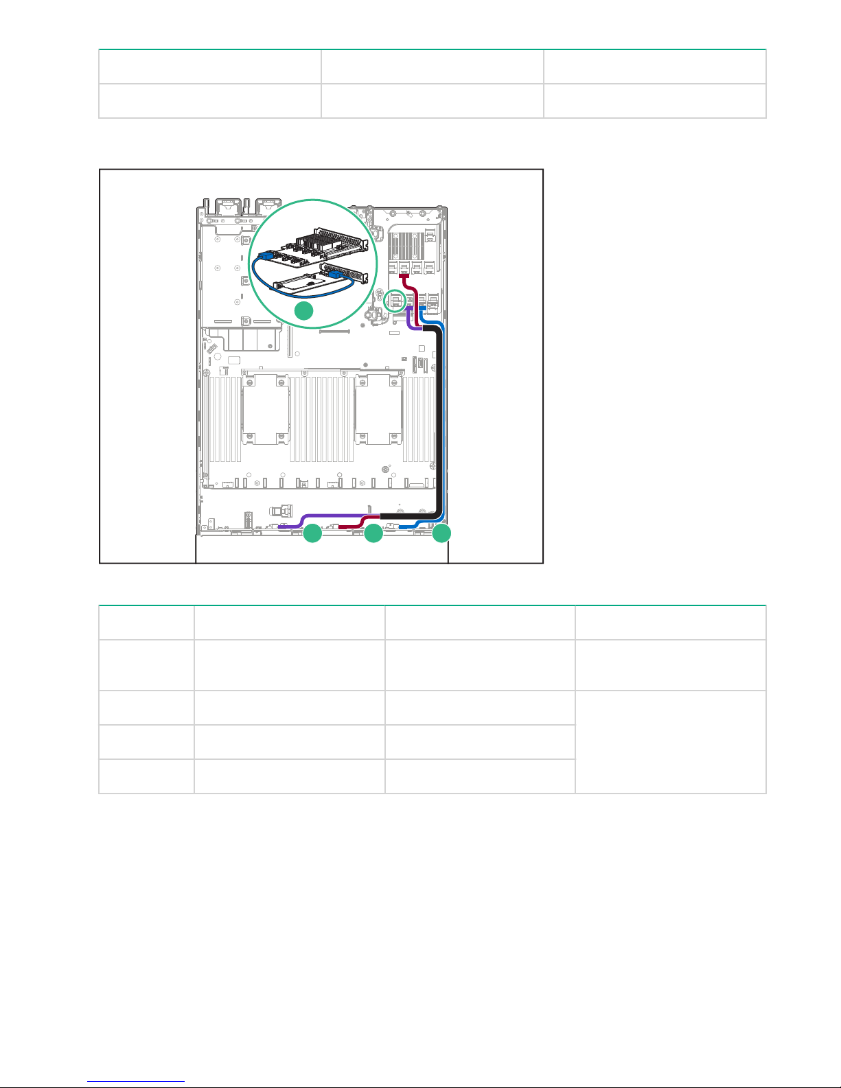
From To SAS cable
1
2 3 4
Port on backplane Port on RAID controller card 780423–001
HPE StoreOnce 3500 Series internal SAS cabling
Figure 19: Internal SAS cabling for HPE StoreOnce 3500 Series
Item From To Cable
1 Port 1, RAID controller (slot3)Port 1, SAS expander (slot 2) 729357–001
2 Port 5, SAS expander Port 1, backplane 784627–001 (kit for all three
SAS expander to backplane
3 Port 4, SAS expander Port 2, backplane
cables)
4 Port 3, SAS expander Port 3, backplane
52 HPE StoreOnce 3500 Series internal SAS cabling
Page 53

HPE StoreOnce 5100 System internal SAS cabling
1
2
3 4 5
Figure 20: Internal SAS cabling HPE StoreOnce 5100 System
Item From To Spares Part Number
1 Port 1, RAID controller (OS) Rear drive cage 784625-001
2 Port 1, RAID controller (slot3)Port 1, SAS expander (slot 2) 729357–001
3 Port 5, SAS expander Port 1, backplane 784627–001 (kit for all three
4 Port 4, SAS expander Port 2, backplane
5 Port 3, SAS expander Port 3, backplane
System boot and RAID controller failure
HPE StoreOnce 3100, 3520 and 3540 Systems boot from the p1224 RAID controller that is also connected to
the customer data storage disks.
HPE StoreOnce 5100 Systems boot from the onboard smart array controller which is connected to the two
OS disk drives in the rear of the server.
If a catastrophic failure of the boot RAID controller occurs, the system will not boot. This failure may only be
diagnosed from the server POST messages where the controller may report an error or a lockup code. In
these cases, contact HPE Support and provide information about the reported error code.
SAS expander to backplane
cables)
Other forms of noncatastrophic RAID controller failure will be reported in the Event Log and the Hardware
pages on the StoreOnce GUI.
HPE StoreOnce 5100 System internal SAS cabling 53
Page 54

NOTE:
1
2 3 4
6
5
If RAID fails and the HPE StoreOnce System is still functioning, you can also get information, including
license keys, by generating a Support ticket.
Replacing the RAID components
When replacing the p1224 controller or SAS expander card, be sure to replace the card into the same slot
from which it was removed. Make sure that the card is connected to the SuperCapacitor module and to the
internal SAS data storage. On an HPE StoreOnce 5100 System, if the system has been expanded, also
connect the card to the external SAS storage.
CAUTION:
To reduce the risk of personal injury or damage to the equipment, consult the safety information and
user documentation provided with the server and RAID component before replacing it.
p1224 RAID controller
The p1224 RAID controller card is located in:
• HPE StoreOnce 3100 System: PCIe slot 1 and is connected to the backplane.
• HPE StoreOnce 3500 Series and HPE StoreOnce 5100 System: PCIe slot 3 and is connected to the SAS
expander card in slot 2 and to the backplane. In the HPE StoreOnce 5100 System, it is also connected to
any external SAS storage.
Figure 21: HP p1224 RAID card
1
Connector to external SAS storage (HPE 5100
only)
3
Cache module
5
SuperCapacitor connector
54 Replacing the RAID components
2
Connector to internal SAS disks
4
SuperCapacitor (located in the center of the
unit, clipped to the floor of the chassis behind
the disk cage)
6
LEDs
Page 55
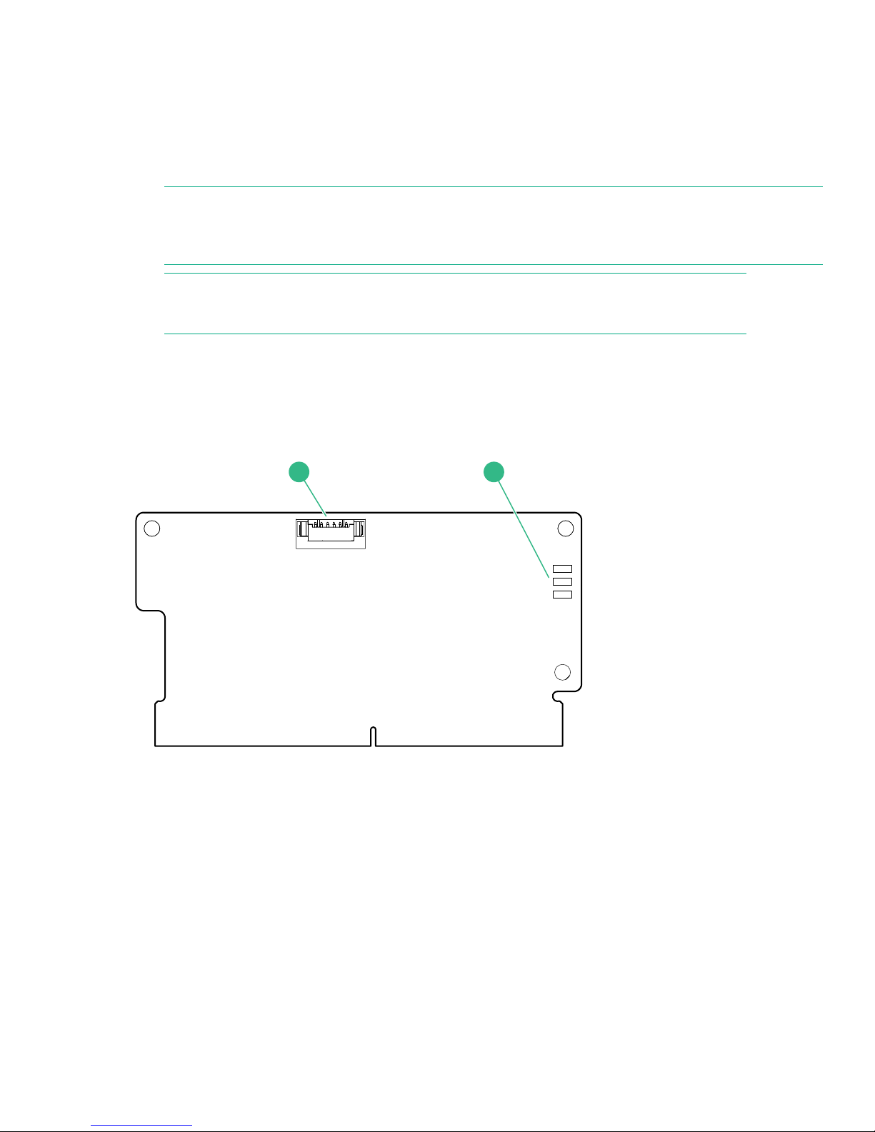
The RAID cache module and SuperCapacitor
1
2
There is one SuperCapacitor and cache module for each RAID Controller. The RAID cache module is slotted
onto the RAID card; the SuperCapacitor is located in the center of the unit, clipped to the floor of the chassis
behind the disk cage.
These items ensure that cache contents are maintained after a loss of power. The LEDs on the cache module
flash when the SuperCapacitor is disconnected and POST error messages provide more information.
NOTE:
The recommendation is to replace both the SuperCapacitor and RAID cache module at the same time,
regardless of which element has failed.
NOTE:
Never move cache modules from one RAID controller to another within or between systems.
If the SuperCapacitor is disconnected on the RAID card in the HPE StoreOnce System, the system will not
boot. If boot fails, it is a good idea to check that the SuperCapacitor is seated correctly.
If the SuperCapacitor or cache module has failed, the system may still boot with error messages and it will run
more slowly. Remove and dispose of the old module, and replace it with the new one. Check that the cable is
connected correctly to the SuperCapacitor.
Figure 22: SuperCapacitor module connector on RAID card
1
SuperCapacitor connector
HPE SAS expander card (HPE StoreOnce 5100 System and HPE StoreOnce
3500 Series)
If no disks are showing on the Storage-Shelves page of the StoreOnce GUI, there may be a problem with the
HPE SAS expander card.
The part number for a replacement card is: 761879-001. It must be installed in PCIe slot 2.
Mini-SAS cables connect the RAID controller card to the SAS expander card, and the SAS expander card to
the hard disk drive backplane.
2
LEDs
The RAID cache module and SuperCapacitor 55
Page 56

NOTE:
3
2
1
2
1
Tuck the mini-SAS cables to be routed to the backplane into the side of the chassis. See Figures 17 and
18.
Replacing the HPE SAS expander card
The following example describes how to replace the p1224 card. The general procedure is the same to
access the SAS expander card or the SuperCapacitor cache module.
Procedure
1. Power off the HPE StoreOnce System. Observing the safety and anti-static procedures, remove all
external cabling to the PCIe cards. Remove the cover from the HPE StoreOnce System, as described in
the appropriate HPE ProLiant Maintenance and Service Guide.
a. The HPE StoreOnce 3500 Series and HPE StoreOnce 5100 System may have a PCIe 10GbE
Network or Fibre Channel card in slot 1.
b. The HPE StoreOnce 5100 System may be connected to external SAS storage.
2. Remove the PCIe riser cage (for slots 1 to 3) and locate the p1224 controller card in slot 3. Detach the
cables connecting the p1224 card to the SuperCapacitor, and the SAS storage.
3. As shown in the following figure, unclip the blue retaining latch on the PCIe card (1 and 2) and remove
the PCIe card (3).
Figure 23: Removing a p1224 card
4. Install the new p1224 card (1) and check that it is seated properly. Close the blue PCIe card retaining
latch (2).
Figure 24: Inserting a p1224 card
5. Reconnect all internal SAS cables. See Internal SAS cabling on page 51 and the hood label for internal
SAS cabling.
56 Replacing the HPE SAS expander card
Page 57

IMPORTANT:
The HPE StoreOnce 3500 Series and HPE StoreOnce 5100 System may have a PCIe 10GbE
Network or Fibre Channel card in slot 1. Verify that this card has not been dislodged.
6. Replace the PCIe riser cage and the server cover, as described in the appropriate HP ProLiant
Maintenance and Service guide.
7. Reconnect all external cables.
8. Power on the HPE StoreOnce System
9. Once rebooted, the HPE StoreOnce System will identify the new RAID controller and will remap the
existing disk storage volumes and enclosures to the controller. It will take 5 to 10 minutes for the process
to complete. During this time, the product will be online but several warning events will be generated and
the GUI Hardware and Events pages will show errors being reported and cleared.
10. Verify the firmware and upgrade, if necessary.
Replacing the p1224 RAID controller and components 57
Page 58

Disk replacement
1
2
3
4
5
6
7
8
9
10
11
12
Disk numbering
This chapter describes how to replace individual disks within a RAID set.
NOTE:
For instructions on how to connect additional storage to an HPE StoreOnce 5100 System by adding a
capacity upgrade enclosure (not available with the HPE StoreOnce 3500 Series and HPE StoreOnce
3100 System), see the printed documentation supplied with the additional storage.
Figure 25: Disk numbering in HPE 3500 and 5100 Systems
RAID configuration
All HPE StoreOnce Systems are supplied with their base storage already configured for use.
Table 16: RAID configuration
HPE StoreOnce
model
HPE StoreOnce
3100 System
HPE StoreOnce
3500 Series
HPE StoreOnce
5100 System
Number of disks
(and location)
4 x 2 TB This model uses a RAID 5 system; operating system and
3520 = 12 x 2 TB
3540 =12 x 4 TB
2 x 900 GB for the
OS in the rear of the
server unit
Notes
backup data are stored on the same RAID Set.
RAID 5 allows for a single drive failure without loss of either the
backup data or OS partitions.
Both systems have two RAID 6 (4+2) sets. The basic capacity is
capped at 50% of the available usable capacity. A software
license is required to use the full capacity. No additional
hardware is required.
No further enclosures may be added.
The two OS disks in the rear disk bays are dedicated for use by
the operating system and are in a mirrored configuration, such
that one disk can be lost without the system failing.
Plus 12 x 4 TB in
front disk bays
58 Disk replacement
The 12 storage disks in the front disk bays are in a RAID 6 (9+2
+ 1 hot spare) set, such that two disks can be lost without loss
of backup data. The hot spare disk is in bay 12.
Up to five additional enclosures may be added to increase the
backup data capacity, also RAID 6 (9+2 + 1 hot spare).
Page 59

IMPORTANT:
It is important that failed disks are replaced promptly.
To ensure that you are alerted to disk failures, ensure that either or both of SNMP traps and email alerts
are configured. If a disk failure occurs, you will receive notification immediately and can replace the
disks.
Note the following:
• HPE StoreOnce 5100 System: All enclosures of storage must be working for the system to operate; if any
RAID set fails on any one enclosure due to exceeding the maximum number of failed disks then ALL data
is lost.
• HPE StoreOnce 3500 Series: All 12 disks are used for data storage with or without the license to expand
the storage capacity to 100%.
• HPE StoreOnce 3100 System: If more than one disk fails, then the data and operating system are lost and
a “Quick Restore” of the appliance OS will be required before the unit can be used again.
Hot spare disk and LEDs on the HPE StoreOnce 5100 System
Both the HPE StoreOnce 5100 System and any Capacity Upgrade enclosures have a hot spare disk in bay
12. If one disk fails in the RAID set, the hot spare disk automatically takes it place until the failed disk is
replaced. The behavior of the LEDs on the hot spare disk is as follows:
• Head server: The LED is off on the hot spare disk until it becomes active due to the failure of another disk
in the RAID set. It is flickering green when in use.
• Capacity Upgrade enclosure: The LED is solid green on the hot spare disk until it becomes active due to
the failure of another disk in the RAID set. It is flashing green when in use.
Ordering the correct replacement disk for a failed disk
IMPORTANT:
HPE strongly recommends replacing a failed disk with a fresh disk from the factory. Do not substitute a
disk from another RAID set.
HPE StoreOnce 5100 System: If a disk fails, it is important to identify whether the disk is in one of the two OS
disk bays or one of the storage disk bays. Different disks are used in the two locations and the carriers are
different.
Always quote the serial number and product number for the enclosure that contains the failed disk so that
support can replace the correct part.
Hot spare disk and LEDs on the HPE StoreOnce 5100 System 59
Page 60

Table 17: Disk types
Disk Where used Spares Part Number
900GB entry SAS Level HDD HPE StoreOnce 5100 System (2
disks), head server unit, rear disk
bays
4 TB HDD HPE StoreOnce 5100 System (12
disks), head server unit, front disk
bays
HPE StoreOnce 3540 System (12
disks)
4 TB HDD HPE StoreOnce 5100 System (12
disks), capacity upgrade
expansion
2 TB HDD HPE StoreOnce 3520 System (12
disks)
HPE StoreOnce 3100 System (4
disks)
Replacing a hot-plug hard disk
Procedure
653971-001
695842-001
844894-001
653948-001
1. Identify the disk that has failed as described above.
NOTE:
Remember you can use the Beacon LED to identify the physical disk in the storage controller or
expansion shelves.
2. Remove the disk.
a. Press the hard disk carrier button (1) to release the ejector lever.
b. Pull out the disk carrier handle and slide the hard drive assembly out of the drive bay. Be sure to
support the drive when pulling it out of the cage.
60 Replacing a hot-plug hard disk
Page 61

Figure 26: Removing the hard drive
3. Replace the failed disk with the new disk.
4. Push the hard drive assembly (1) into the drive bay until it stops and press the HDD carrier latch (2) inward
until it clicks.
Figure 27: Installing a replacement hard disk
5. Log in to the GUI and look at the Hardware — SmartArray Controller — Enclosure — Hard Disk page.
Check the status of the drives.
NOTE:
It may take several minutes for the status to report that the disk replacement has completed
successfully and that the new disk is being rebuilt as part of the RAID group. During this time several
alerts will be generated reflecting the status of the physical disks and the logical storage system.
6. Run the StoreOnce CLI command, hardware show firmware, to check that the firmware on the new
disk is correct; it will be listed under the storage details. Run the StoreOnce CLI command, hardware
update firmware, with appropriate parameters to update it, if necessary. See the HP StoreOnce
Backup CLI Reference Guide for more details.
Disk replacement 61
Page 62

Rebuilding storage if multiple disks fail and a RAIDset is
broken
This section explains how to rebuild your storage in the event of a complete data loss. This should be done
under the guidance of HPE Support.
After the failed disks have been replaced it will be necessary to remove the old filesystem configuration and
rebuild a new one as follows:
Procedure
1. Use the following StoreOnce CLI to remove all configured storage on the appliance (except that used by
the operating system):
hardware delete storage all
WARNING:
This command will completely remove all configured storage, and will run at any time even if the
storage is healthy.
This will clean up all filesystem configuration and delete logical drives (LUNs) on all storage devices.
2. After the delete command has completed rebuild the storage system using the following StoreOnce CLI
commands to discover and add storage to the system
hardware discover storage
hardware add storage
This will configure both the storage in the appliance (base storage) and any attached expansion shelves.
Licenses must be present for all attached storage before the command will complete successfully. If
insufficient licenses are available, no storage will be configured.
62 Rebuilding storage if multiple disks fail and a RAIDset is broken
Page 63

StoreOnce Optional Hardware
Support for StoreOnce Optional Hardware
NOTE:
This chapter is not applicable to the HPE StoreOnce 3100 System because it does not support Optional
Hardware.
The HPE StoreOnce 3500 Series and HPE StoreOnce 5100 System support the addition of 10 GbE Network
cards and Fibre Channel cards. The StoreOnce CLI and GUI will report any errors to the user.
Error messages
The following table details messages that indicate problems with the Optional Hardware. Other error
messages may be displayed that relate to licensing issues. See the HPE StoreOnce Optional Hardware
Installation and Configuration Guide for more details.
Table 18: Messages that indicate problems with Optional Hardware
Short message Error message Description Recommended Action
Failed Failed hardware found There is a valid license
but the hardware is in a
failed/degraded state
Unlicensed Invalid hardware found
(License mismatch)
Degraded Hardware reported as
degraded
Missing Hardware missing The hardware is missing. A card was previously
The hardware is valid but
does not match the
license
The hardware is reported
as degraded.
Contact HPE Support.
One type of card has
been and installed and
licensed, and then
replaced with a different
type of card. Either put
back the original card or
contact HPE support and
ask them to delete the
original license and apply
the new one.
Contact HPE Support.
installed but cannot now
be found. The card may
have been removed or
has failed. Verify that the
card is in the correct slot
and is still functioning.
Table Continued
StoreOnce Optional Hardware 63
Page 64

Short message Error message Description Recommended Action
Incorrect Card installed in the
wrong PCI-E slot
Faulty Hardware reporting as
failed
Unsupported Unsupported hardware
found
Invalid Invalid Hardware The hardware is invalid
The card is in the wrong
PCIe slot.
Hardware is in a failed
state
Hardware is unsupported
type/model
(generic error)
It is likely that a card has
been installed in the
wrong slot. Put the card
in the correct slot and try
to activate again.
It can also occur if a card
fails in a lower-order slot.
If the NIC in slot 1 fails
and you are adding a NIC
to slot 4 then slot 1 would
display MISSING or
FAILED and slot 4 would
display Invalid load
order.)
Contact HPE Support.
Verify that you have
installed the appropriate
HPE StoreOnce Optional
Hardware.
Contact HPE Support.
Replacing Optional Hardware cards
NOTE:
Providing the replacement card is of the same type and is installed in the same slot, no re-activation or
re-licensing is required.
Follow the instructions in the HPE StoreOnce Optional Hardware Installation and Configuration Guide to
install the replacement card. The following additional guidelines apply to the replacement procedure:
Procedure
1. Replace a 10GbE SFP card with another 10GbE SFP card, a 16Gb FC card with another 16Gb FC card,
and an 8Gb FC card with another 8Gb FC card.
2. Replace the card in the same slot from which the failed card was removed.
Fibre Channel card considerations
Describes Optional Hardware FC replacement considerations and is identical for 5500 and 6600.
For those products that have Fibre Channel cards, the following VTL and StoreOnce Catalyst device
configuration notes apply:
• If using only VTL over Fibre Channel, no further configuration is required when replacing the Fibre
Channel card.
• If using StoreOnce Catalyst over Fibre Channel there are replacement considerations. The World Wide
Port Name (WWPN) and World Wide Node Name (WWNN) of the StoreOnce Catalyst over Fibre Channel
64 Replacing Optional Hardware cards
Page 65

device presented on a StoreOnce Fibre Channel port currently uses the WWPN / WWNN of the FC card.
StoreOnce generated WWPNs / WWNNs are not used. Replacing the FC card will result in a new Catalyst
over Fibre Channel WWPN / WWNN. After replacing a FC card the StoreOnce user will need to re-zone
their clients with the new WWPN / WWNN. The replaced port will not be seen by clients until this re-zoning
is performed.
Removing and replacing a Fibre Channel or 10 GbE optical
SFP
The SFP is on the rear of the server and serves as the port for connecting to the FC SAN or 10GbE network.
Make sure that you have the correct SFP for the connection type.
WARNING:
When the system is on, do not stare at the optical transceivers. Doing so could damage your eyes.
Procedure
1. Disconnect the FC or 10GbE cable and lift the retaining clip so that you can slide the SFP carefully out of
the enclosure.
2. Remove the replacement SFP module from its protective packaging.
CAUTION:
When handling the SFP, do not touch the gold contact leads to prevent damage.
3. Carefully slide the replacement SFP into the enclosure until fully seated, close the retaining clip to secure it
in place.
NOTE:
Make sure that you use the correct SFP module—for a 10 GbE network port, an 8 Gb FC, or a 16 Gb
FC port, as appropriate.
4. Place the failed SFP into the packaging for return to HPE.
5. Reconnect the FC or 10GbE network cable to the SFP and verify that the link status LED is correct.
Removing and replacing a Fibre Channel or 10 GbE optical SFP 65
Page 66

HPE StoreOnce 5100 System Capacity Upgrade
expansion shelves
HPE StoreOnce 5100 System Capacity Upgrade hotpluggable components
NOTE:
This chapter is not relevant for the HPE StoreOnce 3500 Series or the HPE StoreOnce 3100 System.
The HPE StoreOnce 5100 System supports capacity expansion by the addition of up to five Capacity
Upgrade Kits.
The system must be taken offline before replacing most components. The only parts that are hot-pluggable
are:
• Hard disks: follow the same procedure as replacing a hard disk in the server.
• Fan modules
• Power supply modules
NOTE:
Before replacing the I/O module or SAS cables, thoroughly check that all cables are fully seated and
connected. Refer also to the instructions supplied with the I/O module and to earlier sections in this
guide for illustrations showing SAS cabling.
Removing and replacing the I/O module
Procedure
1. Power down the HPE StoreOnce 5100 System.
2. Unplug the cables from the back panel of the I/O module.
3. If the I/O module is in the only Capacity Upgrade expansion shelf or the last shelf in the daisy chain, there
is one cable to disconnect. If it is one of several daisy-chained Capacity Upgrade shelves, there will be two
cables to disconnect on the I/O module.
4. Loosen the captive retaining thumbscrew (1), and swing out the hood latch (2).
66 HPE StoreOnce 5100 System Capacity Upgrade expansion shelves
Page 67
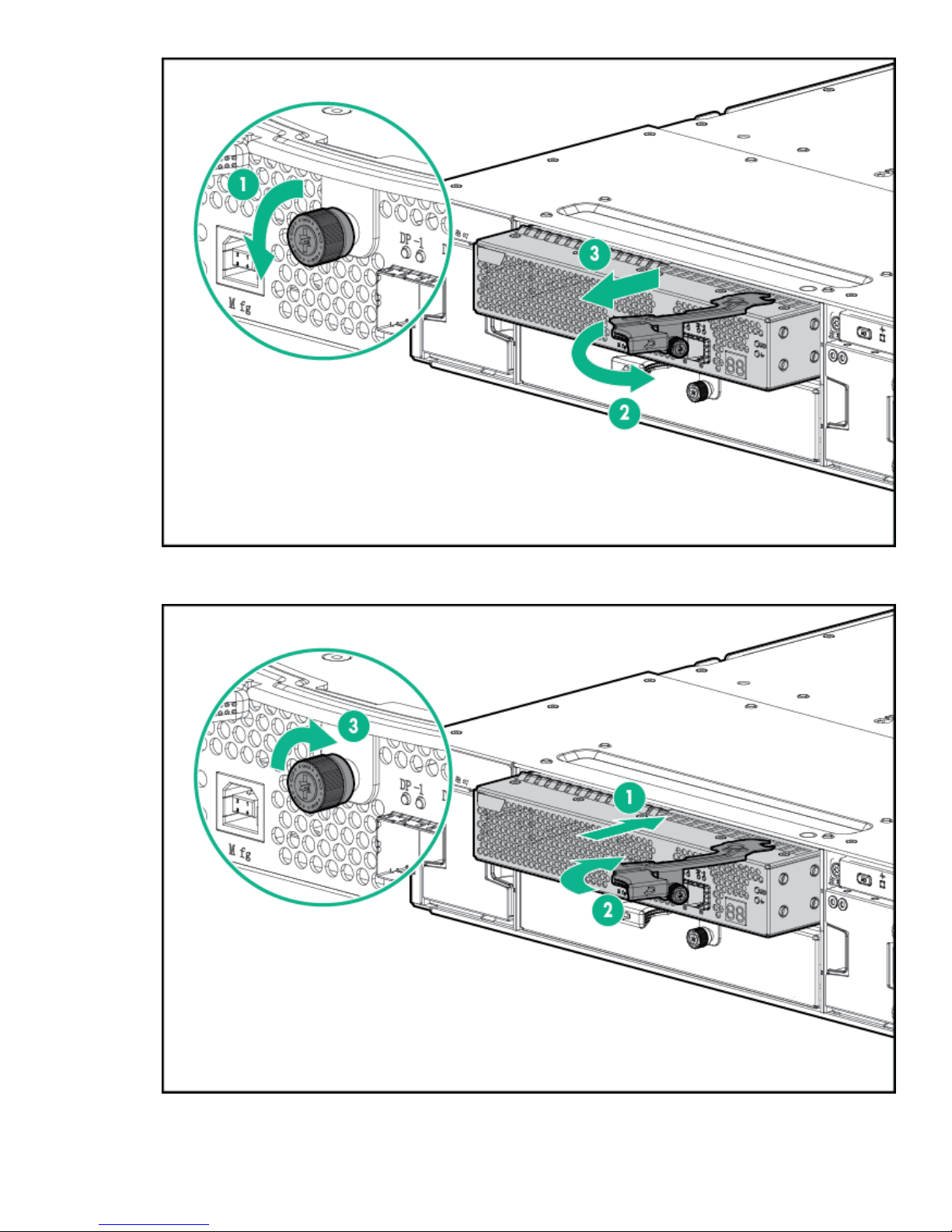
5. Slide out the I/O module (3) and set aside.
6. Slide the replacement I/O module into the correct bay and swing in the hood latch until it closes.
HPE StoreOnce 5100 System Capacity Upgrade expansion shelves 67
Page 68

7. Retighten the captive retainer thumbscrews
1 2
8. Replace the I/O cables.
1 SAS IN from RAID controller in server or from previous enclosure
2 SAS OUT to next enclosure
9. Read the LEDs and confirm that the unit is operating.
Removing and replacing a power supply module
Procedure
1. Remove the power cable from the power supply to be replaced.
2. Press the latch (1) and slide the power supply module out of the enclosure (2).
NOTE:
If one of the PSUs is removed and reinserted, but the power cord is not reattached, the hardware report
will show the failed AC Supply and a TempSensor Failure.
3. Slide the replacement power supply into the enclosure bay until it clicks into place.
68 Removing and replacing a power supply module
Page 69

4. Connect the power cable.
5. To ensure the module is operating properly, check the power supply module status LED.
Removing and replacing a fan module
WARNING:
To maintain the correct airflow to the HPE StoreOnce system, this procedure must be completed within
3 minutes.
Procedure
1. Press the fan module release buttons (1) and slide the module (2) out of the enclosure.
2. Slide the replacement fan module into the enclosure until it clicks into place
3. To ensure the module is operating properly, check the fan module status LEDs.
Removing and replacing a fan module 69
Page 70
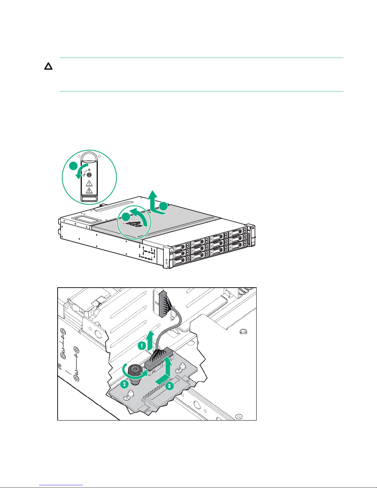
Replacing the fan control card
1
2
3
This procedure must be performed only after HPE Support determines that the fan control card is the source
of the problem and recommends that the fan control card be replaced.
CAUTION:
This procedure requires removing the enclosure from the rack. Before removing the enclosure, power
down the HPE StoreOnce 5100 System.
Procedure
1. Disconnect all cables from the enclosure, including the power cables.
2. Remove the fan modules.
3. Remove the enclosure from the rack.
4. Pull the hood latch up and back (1 and 2), and lift the enclosure cover up and remove it (3).
5. Remove the fan control card cable (1).
6. Loosen the captive thumbscrew (2).
7. Slide the fan control card sideways to free it from the retaining pins and lift it out (3).
70 Replacing the fan control card
Page 71

8. Insert the new fan control card and slide it sideways to engage it with the retaining pins.
1
2
3
9. Tighten the captive thumbscrew.
10. Attach the fan control card cable.
11. Install the enclosure cover and press the hood latch down to engage the latch.
12. Install the enclosure in the rack.
13. Tighten the front retaining screws.
CAUTION:
The front retaining screws must be attached at all times when the enclosure is racked.
14. Install the fan modules.
15. Reconnect all cables to the enclosure, including the power cables.
16. When the enclosure has completed its power-on sequence, check all enclosure status LEDs to ensure
that the enclosure is operating properly.
Removing and replacing the power distribution board
This procedure must be performed only after HPE Support determines that the enclosure is the source of the
problem and recommends that the power distribution board be replaced
CAUTION:
This procedure requires removing the enclosure from the rack. Before removing the enclosure, power
down the HPE StoreOnce 5100 System.
Procedure
1. Disconnect all cables from the enclosure, including the power cables.
2. Remove the power supplies.
3. Remove the rear hold down bracket.
4. Remove the enclosure from the rack.
5. Pull the hood latch up and back (1 and 2), and lift the enclosure cover up and remove it (3).
6. Loosen the captive thumbscrew (1) on the air guide.
Removing and replacing the power distribution board 71
Page 72

7. Remove the power cables from the backplane.
8. Lift the air guide, pull it toward the front of the enclosure and remove it (2).
9. Loosen the captive thumbscrew on the power distribution board.
10. Slide the power distribution board toward the front of the enclosure and lift it out of the enclosure.
11. Install the replacement power distribution board in the enclosure and slide it toward the back of the
enclosure.
12. Tighten the captive screw to secure the power distribution board.
13. Connect the power cables to the backplane.
14. Install the air guide making sure that all cables are routed through the air guide opening.
15. Tighten the captive screw to secure the air guide in the enclosure.
16. Install the enclosure cover and press the hood latch down to engage the latch.
17. Install the enclosure in the rack.
18. Install the power supplies.
19. Reconnect all cables to the enclosure, including the power cables.
20. When the enclosure has completed its power-on sequence, check all enclosure status LEDs to ensure
that the enclosure is operating properly.
Removing and replacing the enclosure backplane
The operation is performed after HPE Support determines that the enclosure backplane is the source of the
issue and recommends that the backplane be replaced
IMPORTANT:
After replacement and power up, it is necessary to rewrite warranty serial numbers into BIOS. Contact
HPE Support for more information.
Procedure
1. Before removing the enclosure, power down the HPE StoreOnce 5100 System.
2. Disconnect all cables from the enclosure, including the power cables.
3. Label all the disk drives before removing them to ensure that they are reinstalled in the proper enclosure
bays.
4. Remove all the disk drives.
5. Remove the power supplies.
6. Remove the I/O module.
72 Removing and replacing the enclosure backplane
Page 73

7. Remove the fan modules.
1
2
3
8. Remove the enclosure from the rack.
9. Pull the hood latch up and back (1 and 2), and lift the enclosure cover up and remove it (3).
10. Disconnect the following cables from the backplane:
Number Cable
1 Front UID health module
2 Fan control card
3 Fan control card
4 Rear UID health module
5 Power distribution unit
Table Continued
HPE StoreOnce 5100 System Capacity Upgrade expansion shelves 73
Page 74

Number Cable
6 Rear UID health module
7 Power supply
8 Power supply
11. Remove the eight drive cage retaining screws. There are four to a side.
NOTE:
The StoreOnce System has 12 hard disks and the screws are in the 12LFF HDD Cage location.
12. Slide the drive cage toward the front of the enclosure and lift free of the enclosure.
13. Remove the two screws attaching the back plane to the drive cage.
14. Slide the back plane toward the top of the drive cage and lift the back plane off the drive cage.
15. Place the replacement back plane on the drive cage and slide toward the bottom of the drive cage on to
the retaining hooks.
16. Install the two back plane screws.
17. Place the drive cage in the enclosure and slide toward the back of the enclosure making sure the
locating pins in the bottom of the enclosure are all correctly located in the drive cage.
NOTE:
Depending on the specific unit, there are 6 or 8 locating pins.
18. Install the eight drive cage retaining screws.
19. Connect the two UID/Health module cables.
20. Connect the power cables.
21. Connect the fan control card cables.
22. Install the enclosure cover and press the hood latch down to engage the latch.
23. Install the enclosure in the rack.
24. Install the I/O module.
25. Install the power supplies.
26. Install the fan modules.
27. Install the disk drives in the same bays they were in the original enclosure.
74 HPE StoreOnce 5100 System Capacity Upgrade expansion shelves
Page 75

28. Reconnect all cables to the enclosure, including the power cables.
29. When the enclosure has completed its power-on sequence, check all enclosure status LEDs to ensure
that the enclosure is operating properly.
Removing and replacing an enclosure
This operation is required before the user can carry out a number of the other tasks described in this chapter.
Procedure
1. Power down the HPE StoreOnce 5100 System.
2. Disconnect all cables from the enclosure, including the power cables.
3. Depending upon the maintenance task, it may be necessary to carry out some of the following tasks:
a. Remove all the disk drives. Make sure that all disks are labeled before removing them to ensure they
can be reinstalled in the proper enclosure bays.
b. Remove the power supplies.
c. Remove the I/O module.
d. Remove the fan modules.
4. Loosen the captive screws behind the latch on the front left and right bezel ears of the chassis (1)
5. Loosen the rear hold-down bracket.
6. Slide the enclosure out of the rack (2) and set it on a secure surface.
WARNING:
Always use at least two people to lift an enclosure into the rack. If the enclosure is being loaded
into the rack above chest level, a third person must assist with aligning the enclosure with the rails
while the other two people support the weight of the enclosure.
7. Carry out appropriate maintenance tasks.
8. Slide the enclosure back into the rack and tighten the retaining screws.
Removing and replacing an enclosure 75
Page 76

9. Reattach the rear hold-down bracket.
10. Reinstall any items that were removed before removing the enclosure.
a. Install the I/O module.
b. Install the power supplies.
c. Install the fan modules.
d. Install the disk drives in the same bays as they were before maintenance.
11. Reconnect the SAS cables and power cables.
76 HPE StoreOnce 5100 System Capacity Upgrade expansion shelves
Page 77

1
2
3
4 1
5
6
4
4
1
iLO
PS2
6
7
8
1
2
3
4
5
Figure 28: SAS cabling showing five storage enclosures below the head server
1 JBOD1 2 JBOD2
3 JBOD3 4 JBOD4
5 JBOD5 6 SAS connector on RAID controller on
head unit
7 P1 connector on I/O module (SAS IN from
head unit or previous expansion shelf)
8 P2 connector on I/O module (SAS OUT to
next expansion shelf)
12. When the enclosure has completed its power-on sequence, check all enclosure status LEDs to ensure
that the enclosure is operating properly.
13. Power on the HPE StoreOnce 5100 System.
HPE StoreOnce 5100 System Capacity Upgrade expansion shelves 77
Page 78

The QR ISO image
The StoreOnce QR ISO image
In the rare occurrence of a complete system failure, it may be necessary to reinstall the product software. This
task is normally carried out on the recommendation and under the supervision of HPE Support.
CAUTION:
The Quick Restore process will delete all stored data and configuration settings returning your product
to factory default settings.
Download Quick Restore ISO Image
The StoreOnce Quick Restore ISO Image is used to install the StoreOnce software image onto the StoreOnce
appliance disks.
Procedure
1. Go to the HPE Support page at http://www.hpe.com/support/hpesc, search on your product and select
HPE StoreOnce Backup.
2. Under Download Options, select the Get drivers, software & firmware link.
3. To display a list of all available downloads, select OS Independent under Operating Systems.
4. The QR ISO image is under Software. The HPE USB Key Utility for Windows can be downloaded from the
Utility option.
5. Click Obtain Software and select the QR ISO image appropriate to your product. You will be required to
sign in with HPE Passport to download the QR ISO image, and can create an HPE Passport account when
you first access the site.
6. Create the physical QR media.
Use the HPE USB Key Utility for Windows to copy the ISO image to a USB key using a Windows PC.
Alternatively, use the iLO4 ISO mounting utility to mount the virtual CD-ROM over iLO.
IMPORTANT:
HPE recommends that you label the new media for ease of identification.
Create a bootable QR USB Stick
Use the HPE USB Key Utility for Windows to copy the ISO image to an 8 GB USB key using a Windows PC.
NOTE:
USB 3 keys are not supported.
Procedure
1. From the Utility link on your product’s Download page, download the Smart Component to a directory on
your hard drive and change to that directory. The downloaded file is a self-extracting executable with a
filename based on the Smart Component Number. From that drive and directory, execute the downloaded
file.
2. After installation, the utility will place a shortcut in HPE System Tools in the Programs start menu folder.
To make your drive key bootable and copy the ISO image to it:
78 The QR ISO image
Page 79

a. Place your HPE USB drive key (minimum size 8 GB flash stick) in an available USB port.
b. Select the HPE USB Key Utility shortcut in the HPE System Tools folder.
3. Once all steps are completed, remove the USB stick from the Windows PC.
Delete storage
Before running QR, it is advisable to remove all configured storage on the appliance. If you do not remove all
configured storage, you may get error messages during QR, reporting the presence of Alien LUNs.
Procedure
1. Use the following StoreOnce CLI to remove all configured storage on the appliance (except that used by
the operating system):
hardware delete storage all
This command will clean up all filesystem configuration and delete logical drives (LUNs) on all storage
devices.
Boot the appliance and install the StoreOnce software
Make sure that power, network, keyboard and monitor, and all expansion enclosures are attached to the
StoreOnce appliance, then insert the QR USB stick into a USB port and power on the system.
After the system powers up and completes self-tests, it will boot from the USB key and launch the Linux
installation process.
After a few seconds, a boot splash screen will appear offering the choice of Restore (R) or Exit (E). To
continue to the installation process, press R.
A warning will now be displayed indicating that all data will be lost after entering “yes”. THIS IS THE LAST
CHANCE TO EXIT THE INSTALL PROCESS WITHOUT DATA LOSS.
Enter “yes” to continue.
The installation process will now continue and will:
Procedure
1. Delete the existing logical storage configuration on the appliance server disks.
2. Create a new logical storage partition; depending on the appliance type this may be a pair of mirrored
3. Install the Operating System and appliance software on the system.
4. After installation completes, you will be prompted to remove the USB stick and reboot. To reboot the
5. During the reboot process, the system will perform an install process and return to the login prompt. During
NOTE:
An error will be displayed: [Firmware Bug]: the BIOS has corrupted hw-PMU resources
(MSR 38d is 330). This error does not have any effect on the StoreOnce solution and is an
expected output during QR. The customer or support engineer does not need to take any action.
disks or a LUN stripe across all disks in the appliance.
system, press a key.
this sequence, you may need to answer questions presented on the console screen.
Delete storage 79
Page 80

Performing a configuration restore
Prerequisites
This process requires the latest configuration files that should have been saved and copied locally to the local
system. You will require the following files:
• <config_filename>.zip
• <config_filename>.txt
• <keystore_filename>.kms (if you have installed the Security Pack license and configured Data at
Rest Encryption on any VTL libraries, NAS shares, or Catalyst stores)
This process is normally carried out after a quick restore (QR) or if a replacement appliance has been
received. It restores the appliance to the same state as it was when the configuration file was created. It is
important that there are no configured backup target devices on the appliance.
IMPORTANT:
During this process, you may be prompted to provide the Cluster ID. The Cluster ID is the same as the
System ID that can be found on the Device Management page of the StoreOnce Management Console.
Its value is assigned in the factory set up process and is a 12–character string in the format
HP<SerialNumber of Appliance>.
Procedure
1. Check the Cluster ID against the value shown in the configuration text file, <config_filename>.txt,
using the StoreOnce CLI command:
system show config
2. If necessary reset the Cluster ID of the cluster to the ID of the original appliance, the cluster ID is shown in
the configuration text file, run the command:
system set cluster <cluster_id>
This step may not be necessary if there has been no replacement hardware or if the serial number of the
original appliance has been copied to the BIOS settings of the replacement appliance.
IMPORTANT:
You can only restore the configuration file to an appliance that has the same cluster ID as the one
from which the configuration was taken.
3. Using the latest <config_filename>.txt file, manually apply all of the settings within this configuration
text file using the StoreOnce CLI commands and instructions exactly as shown. This will ensure that the
customer configuration is restored to its previous configuration. It is important that this is done manually
before attempting to restore the device settings automatically.
NOTE:
If the product has additional storage connected, ensure that Capacity Upgrade Kit licenses are
applied.
4. Reconfigure the storage for the appliance using the commands:
hardware discover storage
hardware add storage
5. Monitor the expansion using the following command:
system show status
This command will return either of the following after an add command has been sent:
80 Performing a configuration restore
Page 81

• Adding X,XXXGB...
• Formatted XXGB, which means that the storage and file system has been configured and is ready for
use. Parity initialization may still be in progress.
The following output is an example; the values shown may not match your appliance-specific values.
# system show status
Status
------
Formatted 15,070.76GB
Service Sets Status Notes
------------ ------ -----
Set 1 Running
NOTE:
The addition of storage will take a minimum of two hours to complete. You will not be able to
complete the next steps until storage is formatted.
6. Using an SFTP client copy the saved configuration zip file to the config folder on the appliance.
• Using Linux
a. sftp Admin@<IP_address>
b. cd config
c. put <config_filename>.zip
d. exit sftp
• Using a Windows sftp client
a. Ensure that the File Protocol is set to SFTP, not SCP.
b. Login as Admin.
c. Copy <config_filename>.zip to config.
7. Use the following StoreOnce CLI command to check that the file has been uploaded:
config show list
8. Run the StoreOnce CLI command:
config restore devices <config_filename>
This command will restore device settings for the appliance.
9. After configuration recovery, backups can be configured and replication mappings re-established to
reverse replicate data back to the appliance (see replication information in the user guide).
The QR ISO image 81
Page 82

Support and other resources
Accessing Hewlett Packard Enterprise Support
• For live assistance, go to the Contact Hewlett Packard Enterprise Worldwide website:
http://www.hpe.com/assistance
• To access documentation and support services, go to the Hewlett Packard Enterprise Support Center
website:
http://www.hpe.com/support/hpesc
Information to collect
• Technical support registration number (if applicable)
• Product name, model or version, and serial number
• Operating system name and version
• Firmware version
• Error messages
• Product-specific reports and logs
• Add-on products or components
• Third-party products or components
Accessing updates
• Some software products provide a mechanism for accessing software updates through the product
interface. Review your product documentation to identify the recommended software update method.
• To download product updates:
Hewlett Packard Enterprise Support Center www.hpe.com/support/hpesc
Hewlett Packard Enterprise Support Center: Software
downloads
Software Depot www.hpe.com/support/softwaredepot
• To subscribe to eNewsletters and alerts:
www.hpe.com/support/e-updates
• To view and update your entitlements, and to link your contracts and warranties with your profile, go to the
Hewlett Packard Enterprise Support Center More Information on Access to Support Materials page:
www.hpe.com/support/AccessToSupportMaterials
IMPORTANT:
Access to some updates might require product entitlement when accessed through the Hewlett Packard
Enterprise Support Center. You must have an HP Passport set up with relevant entitlements.
Customer self repair
www.hpe.com/support/downloads
Hewlett Packard Enterprise customer self repair (CSR) programs allow you to repair your product. If a CSR
part needs to be replaced, it will be shipped directly to you so that you can install it at your convenience.
Some parts do not qualify for CSR. Your Hewlett Packard Enterprise authorized service provider will
determine whether a repair can be accomplished by CSR.
82 Support and other resources
Page 83

For more information about CSR, contact your local service provider or go to the CSR website:
http://www.hpe.com/support/selfrepair
Remote support
Remote support is available with supported devices as part of your warranty or contractual support
agreement. It provides intelligent event diagnosis, and automatic, secure submission of hardware event
notifications to Hewlett Packard Enterprise, which will initiate a fast and accurate resolution based on your
product's service level. Hewlett Packard Enterprise strongly recommends that you register your device for
remote support.
If your product includes additional remote support details, use search to locate that information.
Remote support and Proactive Care information
HPE Get Connected www.hpe.com/services/getconnected
HPE Proactive Care services www.hpe.com/services/proactivecare
HPE Proactive Care service: Supported
products list
HPE Proactive Care advanced service:
Supported products list
Proactive Care customer information
Proactive Care central www.hpe.com/services/proactivecarecentral
Proactive Care service activation www.hpe.com/services/proactivecarecentralgetstarted
Warranty information
To view the warranty for your product, see the Safety and Compliance Information for Server, Storage, Power,
Networking, and Rack Products document, available at the Hewlett Packard Enterprise Support Center:
www.hpe.com/support/Safety-Compliance-EnterpriseProducts
Additional warranty information
HPE ProLiant and x86 Servers and Options www.hpe.com/support/ProLiantServers-Warranties
HPE Enterprise Servers www.hpe.com/support/EnterpriseServers-Warranties
HPE Storage Products www.hpe.com/support/Storage-Warranties
HPE Networking Products www.hpe.com/support/Networking-Warranties
www.hpe.com/services/proactivecaresupportedproducts
www.hpe.com/services/
proactivecareadvancedsupportedproducts
Regulatory information
To view the regulatory information for your product, view the Safety and Compliance Information for Server,
Storage, Power, Networking, and Rack Products, available at the Hewlett Packard Enterprise Support Center:
www.hpe.com/support/Safety-Compliance-EnterpriseProducts
Additional regulatory information
Hewlett Packard Enterprise is committed to providing our customers with information about the chemical
substances in our products as needed to comply with legal requirements such as REACH (Regulation EC No
1907/2006 of the European Parliament and the Council). A chemical information report for this product can be
found at:
Remote support 83
Page 84

www.hpe.com/info/reach
For Hewlett Packard Enterprise product environmental and safety information and compliance data, including
RoHS and REACH, see:
www.hpe.com/info/ecodata
For Hewlett Packard Enterprise environmental information, including company programs, product recycling,
and energy efficiency, see:
www.hpe.com/info/environment
Documentation feedback
Hewlett Packard Enterprise is committed to providing documentation that meets your needs. To help us
improve the documentation, send any errors, suggestions, or comments to Documentation Feedback
(docsfeedback@hpe.com). When submitting your feedback, include the document title, part number, edition,
and publication date located on the front cover of the document. For online help content, include the product
name, product version, help edition, and publication date located on the legal notices page.
84 Documentation feedback
Page 85

Additional regulatory information
Belarus Kazakhstan Russia marking
Manufacturer and Local Representative Information
Manufacturer information:
• Hewlett Packard Enterprise Company, 3000 Hanover Street, Palo Alto, CA 94304 U.S.
Local representative information Russian:
• Russia:
• Belarus:
• Kazakhstan:
Local representative information Kazakh:
• Russia:
• Belarus:
• Kazakhstan:
Manufacturing date:
The manufacturing date is defined by the serial number.
CCSYWWZZZZ (serial number format for this product)
Valid date formats include:
Additional regulatory information 85
Page 86

• YWW, where Y indicates the year counting from within each new decade, with 2000 as the starting point;
for example, 238: 2 for 2002 and 38 for the week of September 9. In addition, 2010 is indicated by 0, 2011
by 1, 2012 by 2, 2013 by 3, and so forth.
• YYWW, where YY indicates the year, using a base year of 2000; for example, 0238: 02 for 2002 and 38 for
the week of September 9.
Turkey RoHS material content declaration
Ukraine RoHS material content declaration
86 Turkey RoHS material content declaration
 Loading...