

Page 1

Service and maintenance guide for
StoreOnce 4900 Backup updated
for 3.15.x software
Abstract
This is the Maintenance and Service guide for the HPE StoreOnce 4900 Backup products and has been updated for
3.15.x software. These products are also sometimes referred to as StoreOnce Backup single node rack products.
Part Number: BB903-90956
Published: September 2016
Edition: 8
Page 2

© Copyright 2014–2016 Hewlett Packard Enterprise Development LP
The information contained herein is subject to change without notice. The only warranties for Hewlett Packard Enterprise products and services
are set forth in the express warranty statements accompanying such products and services. Nothing herein should be construed as constituting
an additional warranty. Hewlett Packard Enterprise shall not be liable for technical or editorial errors or omissions contained herein.
Confidential computer software. Valid license from Hewlett Packard Enterprise required for possession, use, or copying. Consistent with FAR
12.211 and 12.212, Commercial Computer Software, Computer Software Documentation, and Technical Data for Commercial Items are licensed
to the U.S. Government under vendor's standard commercial license.
Links to third-party websites take you outside the Hewlett Packard Enterprise website. Hewlett Packard Enterprise has no control over and is not
responsible for information outside the Hewlett Packard Enterprise website.
Acknowledgments
Microsoft® and Windows® are trademarks of the Microsoft group companies
Adobe® and Acrobat® are trademarks of Adobe Systems Incorporated.
Java® and Oracle® are registered trademarks of Oracle and/or its affiliates.
UNIX® is a registered trademark of The Open Group.
Revision History
January 2014Revision 1
This is the initial edition of this guide for HP StoreOnce 4900 Backup
June 2014Revision 2
This edition has updated information for firmware StoreOnce CLI commands.
October 2014Revision 3
The part number for the PCIe riser card PCA has been added. (No change to the document part number.)
March 2015Revision 4
Issued with StoreOnce 3.12.0 software.
August 2015Revision 5
Issued with StoreOnce 3.13.0 software.
April 2016Revision 6
Issued with StoreOnce 3.13.3 software.
September 2016Revision 7
Issued with StoreOnce 3.15.0 software.
Page 3

Contents
1 Part numbers for replacement parts....................................................................5
HPE StoreOnce and HPE ProLiant documentation..............................................................................5
Accessing HPE ProLiant documentation.........................................................................................5
HPE StoreOnce 4900 44TB Backup server .........................................................................................6
HPE StoreOnce 4900 disk enclosure ..................................................................................................6
Accessing the HPE D6000 Disk Enclosure documentation............................................................6
Disk enclosure configurable parts...................................................................................................7
2 General StoreOnce maintenance activities.........................................................8
Preparing for StoreOnce maintenance activities..................................................................................8
HPE StoreOnce Remote Support....................................................................................................8
Powering off.....................................................................................................................................8
Powering on.....................................................................................................................................8
Upgrading BIOS or hardware firmware components............................................................................9
Updating firmware using the StoreOnce GUI..................................................................................9
Updating firmware using the StoreOnce CLI...................................................................................9
Upgrading StoreOnce software..........................................................................................................10
POST messages and troubleshooting................................................................................................10
Tasks that are unique to HPE StoreOnce Backup..............................................................................11
Rack stability.......................................................................................................................................11
3 Identifying problems..........................................................................................12
Example alert for a failed disk.............................................................................................................12
Using the StoreOnce GUI to identify a failed disk..............................................................................12
Viewing the Events Log.................................................................................................................12
Viewing the failed disk in the Hardware tree.................................................................................13
Using the StoreOnce CLI to identify a failed disk...............................................................................13
4 System motherboard replacement....................................................................16
StoreOnce-specific motherboard replacement information................................................................16
Motherboard spares part numbers.....................................................................................................16
DIMM locations...................................................................................................................................16
Identifying the Activation Key for the iLO4 license.............................................................................17
iLO and BIOS configuration after replacing the motherboard.............................................................17
Configuring iLO and RBSU settings..............................................................................................17
RBSU settings...............................................................................................................................18
iLO4 settings..................................................................................................................................18
5 The HP p1228 RAID controller..........................................................................19
The p1228 RAID card in a StoreOnce 4900 server............................................................................19
HP p1228 spares part numbers....................................................................................................19
Location of the HP p1228 RAID cards (server rear view).............................................................20
HP p1228 RAID card ports............................................................................................................20
Identifying a RAID controller failure....................................................................................................20
Replacing the HP p1228 controller.....................................................................................................20
6 RAID cache module and SuperCapacitor failures.............................................23
About the SuperCapacitor and RAID cache module..........................................................................23
Replacing the RAID cache module and SuperCapacitor....................................................................23
7 Replacing Fibre Channel cards.........................................................................25
VTL over Fibre Channel .....................................................................................................................25
StoreOnce Catalyt over Fibre Channel...............................................................................................25
8 Disk enclosures.................................................................................................26
Disk enclosure components................................................................................................................26
Contents 3
Page 4

When replacing Drawer Assembly and Power Block Assembly ........................................................26
Powering on the disk enclosure..........................................................................................................26
Powering off the disk enclosure..........................................................................................................27
After replacing a component...............................................................................................................27
9 Disk replacement...............................................................................................28
StoreOnce 4900 Backup RAID configuration.....................................................................................28
Hot spare disks..............................................................................................................................28
Disk bay locations..........................................................................................................................28
Distributing the disk drives correctly..............................................................................................29
Ordering the correct replacement disk for a failed disk......................................................................29
Replacing a hot plug disk in a disk enclosure.....................................................................................30
Important Safety information.........................................................................................................30
Installing the drives in a StoreOnce disk enclosure.......................................................................30
Rebuilding storage if multiple disks fail and a RAIDset is broken.......................................................32
10 LEDs on StoreOnce Backup systems.............................................................34
LEDs and StoreOnce GUI..................................................................................................................34
HPE StoreOnce 4900 Backup system server ....................................................................................35
HPE StoreOnce 4900 Backup disk enclosure....................................................................................36
Rear view of the disk enclosure....................................................................................................39
Hot-plug drive LEDs............................................................................................................................41
HPE StoreOnce 4900 Backup server units...................................................................................41
Disks in HPE StoreOnce 4900 Backup disk enclosure.................................................................41
1 Gbit ethernet port LEDs...................................................................................................................43
10 Gbit ethernet card LEDs................................................................................................................43
Fibre Channel card LEDs...................................................................................................................44
11 The QR ISO image..........................................................................................45
The StoreOnce QR ISO image...........................................................................................................45
Download Quick Restore ISO Image .................................................................................................45
Create a bootable QR USB Stick........................................................................................................45
Delete storage....................................................................................................................................46
Boot the appliance and install the StoreOnce software .....................................................................46
Performing a configuration restore ....................................................................................................46
12 Support and other resources...........................................................................49
Accessing Hewlett Packard Enterprise Support.................................................................................49
Accessing updates..............................................................................................................................49
Websites.............................................................................................................................................49
Remote Support .................................................................................................................................50
Customer self repair...........................................................................................................................50
Documentation feedback....................................................................................................................50
A Warranty and regulatory information.................................................................52
Warranty information...........................................................................................................................52
Regulatory information........................................................................................................................52
Belarus Kazakhstan Russia marking.............................................................................................52
Turkey RoHS material content declaration....................................................................................53
Ukraine RoHS material content declaration..................................................................................53
4 Contents
Page 5

1 Part numbers for replacement parts
HPE StoreOnce and HPE ProLiant documentation
This Service and Maintenance Guide for HPE StoreOnce Backup products supplements the
ProLiant Maintenance and Service Guides. For hardware issues on the StoreOnce Backup
system, the appropriate ProLiant guide is the primary source of information. Spares part numbers
are provided in the ProLiant guides. This StoreOnce guide contains only information that is not
included in the ProLiant documentation.
The correct ProLiant guide for the server component of the HPE StoreOnce 4900 Backup system
is the guide for the HPE ProLiant DL380p 8SFF G8 server.
IMPORTANT: Always use the StoreOnce CLI commands or the StoreOnce GUI when upgrading
the BIOS, hardware firmware, and StoreOnce software.
More information
Upgrading BIOS or hardware firmware (page 9)
Accessing HPE ProLiant documentation
For more information about replaceable components that are standard for base ProLiant servers:
1. Go to http://www.hpe.com/info/enterprise/docs.
2. Select the Servers & Management Software link.
3. Select HPE ProLiant Gen8 server.
4. Select HPE ProLiant DL380p.
5. Scroll to the Service and maintenance section.
6. Open the guide and look at the Illustrated Parts Catalogue.
The following tables provide a checklist with part numbers of all replaceable components that
are unique to HP StoreOnce Backup systems. These parts and their replacement procedures
are not referenced in the relevant HPE ProLiant server guide and are described only in this guide.
HPE StoreOnce and HPE ProLiant documentation 5
Page 6

HPE StoreOnce 4900 44TB Backup server
This is an offline list, created from partsurfer. If there is a problem with these Spares Part Numbers,
check the online source at: http://partsurfer.hpe.com/search.aspx. If the problem exists in the
online source, use the feedback form to log the problem: http://partsurfer.hpe.com/
ContactUs.aspx.
Table 1 HPE StoreOnce 4900 server spares part numbers
Hot plug?Part numberDescriptionPart
No670521-001Intel Xeon E5-2690 Eight-Core 64-bit processor - 2.90
GHz. See the note at the end of this table.
Processor
No730235-001Intel Xeon E5-2680v2 Ten-Core 64-bit processor - 2.8
GHz. See the note at the end of this table.
Processor
No662522-001Standard efficiency heatsinkProcessor Heatsink
Yes660185-0011200 W, Platinum Plus, 94%PSU
No732143-001Motherboard DL380p IVBMotherboard
No633540-001SmartArray on motherboardCache 512Mb
No684031-001Memory (DIMM) 16GB, PC3-12800R-11, dual-rankMemory DIMM
Yes653954-0011TB, 7,200 rpm, SFF, 6G, dual portHard disk (head server
unit)
Yes832984-0011TB, 7,200 rpm, SFF, 12G, dual port
No634025-001SPS-BD ETHERNET 1Gb 4P 331FLR ADPTR1Gbit FlexLOM Ethernet
Controller
No728099-001SPS-BD PCA 8eRAID controller p1228
(two per system)
No675610-001SPS-CA SFF RIBBON MINISASInternal SAS cable
No660093-001ASSY, CA/CAPACITOR,36",FLSuperCapacitor
No633542-001PCA, DDR3 MINIDIMM MOD 244P 1Gx72RAID cache
No489191-001HP 8Gb Dual Channel PCI-e to Fibre Channel Host
Bus Adapter
Fibre Channel card (two
per system)
Yes468508-001SPS-SFP, 8GB, FC Shortwave8Gb FC SFP+
Yes455885-001ASSY, 10Gb SR SFP+10Gb Ethernet SFP+
No615406-001HP NC552SFP Dual Port 10GbE Server Adapter10 GbE card (two per
system)
No800611-001SPS-BD RISER STORAGEPCIe riser card PCA
HPE StoreOnce 4900 disk enclosure
Accessing the HPE D6000 Disk Enclosure documentation
1. Go to http://www.hpe.com/support/hpesc.
2. Enter D6000 as the product name and click Go.
3. Select HPE D6000 Disk Enclosure from the Results list.
4. Select the Manuals tab, then select the Service and Maintenance link.
6 Part numbers for replacement parts
Page 7
Disk enclosure configurable parts
This is an offline list, created from partsurfer. If there is a problem with these Spares Part Numbers,
check the online source at: http://partsurfer.hpe.com/search.aspx. If the problem exists in the
online source, use the feedback form to log the problem: http://partsurfer.hpe.com/
ContactUs.aspx.
The following table lists the replacement parts for the disk enclosure.
Table 2 Spares part numbers for the disk enclosure
Hot plug?Part numberDescriptionPart
Yes142258-004SPS-CORD AC PWR IEC RT APower cord
No663680-001SPS-ASSY D6000 DRAWER BRICK HDDDrawer*
Yes389015-001SPS-BLANK HD SLIMLN INTRHard disk blank
Yes663681-001SPS-BEZEL EAR RIGHT D6000Right bezel ear
Yes579229-001SPS-POWER SUPPLY 1200W PPower supply
No663679-001SPS-BD D6000 SAS IO MODULEIO module
No712430-001SPS-CHASSIS D6000 LCDLCD
Yes413996-001SPS-FAN SYSTEMFan
No689128-001SPS-ASSY D6000 POWER BLOCK w/POWERPower block*
Yes743405-001SPS-DRV HD 4TB 6G 7.2K 3.5 SAS MDL4 TB Hard disk
No717429-001SPS-CA EXT HYB MSAS HD TO MSASExternal SAS cable, server
to disk enclosure
No408765-001SPS-CA,EXT MINI SAS, 0.5MExternal SAS cable,
between drawers on disk
enclosure
IMPORTANT: * Drawer (663680-001) and Power Block (689128-001) parts must not be
replaced at the same time. Only replace one of these at a time and ensure the D6000 is powered
up for at least 5 minutes before replacing another component in order to preserve the D6000
system values stored in each drawer. See When replacing Drawer Assembly and Power Block
Assembly (page 26).
HPE StoreOnce 4900 disk enclosure 7
Page 8

2 General StoreOnce maintenance activities
Preparing for StoreOnce maintenance activities
• Make sure that you have the correct Maintenance and Service guide for your product. There
are a number of different models, and each product model has its own guide.
• It is best practice to save the system configuration before carrying out maintenance activities
and make sure it is copied to a local PC. Use the StoreOnce CLI command:
config save.
• If you also have the Security Pack license installed and have applied encryption to any VTL
libraries, NAS shares or Catalyst stores, ensure that the latest keystore has been saved.
Use the StoreOnce CLI command:
config save keystore.
See the StoreOnce CLI Reference Guide at http://www.hpe.com/info/storeonce/docs for more
details about these commands.
HPE StoreOnce Remote Support
The preferred HPE Remote Support solution for StoreOnce products is Service Tools and
Technical Support (STaTS). HPE Remote Support monitors StoreOnce appliances and, if issues
arise on the system, allows the appliance to proactively contact Hewlett Packard Enterprise.
Site-specific data is used both proactively and reactively with real-time monitoring and information
extraction tools.
If you have configured HPE Remote Support for use on your system, run the following StoreOnce
CLI command before commencing the maintenance activity to suppress remote event reporting.
system enable remoteeventsuppression "Maintenance Description"
This command prevents a support case being generated during the maintenance task.
To return to normal mode after maintenance, run the StoreOnce CLI command:
system disable remoteeventsuppression "Maintenance Description"
Powering off
If the maintenance activity requires you to power down the system:
1. Use the StoreOnce GUI to power down the server (from the Device Configuration —
Maintenance page).
Or shut down the server using the StoreOnce CLI command:
# system shutdown
2. Switch off the disk enclosures manually using the Power On/Off switch on the back of drawer
2 of each disk enclosure.
Powering on
If it has been necessary to power down the system for maintenance activities, observe the
following sequence to restore power.
1. Switch on the disk enclosures and wait for 30 seconds. The power-on button is on the rear
of Drawer 2.
2. Switch on the server. The power-on button is on the front of the server.
3. Verify the status of the system from the StoreOnce GUI.
8 General StoreOnce maintenance activities
Page 9

Upgrading BIOS or hardware firmware components
Do not upgrade BIOS or hardware firmware components individually using downloads from the
HPE Support website because currently supported firmware component updates are already
embedded within the StoreOnce software. Always use the StoreOnce CLI or the StoreOnce GUI
to implement BIOS and hardware firmware component checks and updates.
Updating firmware using the StoreOnce GUI
1. Select Firmware to view the firmware versions for hardware components, and to update
firmware versions if required.
The Firmware window appears with the following tabs:
• Server: Contains firmware details for all server components.
• Storage: Contains firmware details for all storage components.
2. To perform a check on the currently installed firmware versions for all components, click
Scan .
This action will populate the firmware tabs and may take several minutes to run.
NOTE: If a firmware update is already in progress, the scan will fail.
3. After you have run a Scan, the Recommended Action field in the component list is updated
to show whether individual components require an upgrade or a downgrade. Components
requiring an upgrade are automatically selected. Components requiring a downgrade are
not automatically selected. A downgrade takes longer to complete and is optional for some
components, such as hard drives. It may be carried out separately, if required, after the
upgrade has completed.
NOTE: When the firmware updates are initiated, the backup devices will be taken offline.
Before performing this step, check that there are no outstanding backup jobs pending.
IMPORTANT: Do not shutdown or reboot your system or any system component until the
final step. Special instructions may apply.
4. Click Update Selected or Update All. (Update All will attempt to update all components
that are in the state where there is an update recommended; it will not try to update
components that do not need an update.)
The Status field will show which components are being updated and which updates have
been completed
5. In some cases, when the firmware update has been loaded, you will need to perform a reboot
to complete the firmware update. If a reboot is required, a pop-up message will appear on
your GUI screen after loading is completed. The message will also advise what type of reboot
is required.
• If a software reboot is needed, you will see a message asking if you want to reboot your
system now or later. If you click Yes, your system will be rebooted.
• A power cycle, or cold reboot, requires that the system must be shut down for at least
60 seconds before powering on using the Power-On buttons on the appliance.
Updating firmware using the StoreOnce CLI
1. To show the status of firmware, run the StoreOnce CLI command:
# hardware show firmware <node|storage|all>
2. To see if any firmware needs upgrading, check the Action column .
Upgrading BIOS or hardware firmware components 9
Page 10

IMPORTANT: Do not shut down or reboot your system or any system component until
the final step. Special instructions may apply.
3. Use the hardware update firmware command, as required. For example, there may
be instances where replacement hardware may need a firmware downgrade to bring it in
line with the supported firmware version of the installed StoreOnce software on the system
being maintained. (Use the force parameter in the command to enable this action.)
The command syntax is:
hardware update firmware <node|storage|all>
NOTE: The command will be applied across all server components or across all storage
components. The all parameter updates all firmware components across all components.
There may be instances where replacement hardware may need a firmware downgrade to
bring it in line with the supported firmware version of the installed StoreOnce software on
the system being maintained. Use the force parameter in the command to enable this, but
be aware that the update will take longer to complete.
4. In some cases, when the firmware update has been loaded, you will need to perform a reboot
to complete the firmware update. If a reboot is required, a pop-up message will appear on
your GUI screen after loading is completed. The message will also advise what type of reboot
is required.
• Reboot the system using the StoreOnce CLI command:
system reboot
• Power down the nodes using the StoreOnce CLI command:
system shutdown
After the system has completely shutdown, wait at least 60 seconds before powering
on using the Power-On buttons on the appliance.
Upgrading StoreOnce software
To establish which StoreOnce software version is installed, click on StoreOnce in the Navigator
and look at the Software Revision under System Information.
To find out if a later software release is available, check HPE Support at www.hpe.com/support/
softwaredepot. If it is, download the software release and follow the instructions in the
accompanying Release Notes to install the software.
Supported web browsers
The StoreOnce Management GUI is supported on the following web browsers:
• Internet Explorer 9, 10 and 11 (note that Internet Explorer 8 is not supported and some
StoreOnce features will not work)
• Mozilla FireFox v22 and above and Firefox ESR24
Refer to www.hpe.com/storage/spock for the latest information about which browser versions
are supported.
POST messages and troubleshooting
The StoreOnce Management Console (GUI and Command Line Interface) are the primary sources
of troubleshooting information. However, they do not capture power-on self-test hardware-related
issues. Always refer to the appropriate HPE ProLiant Gen8 Maintenance and Service Guide for
Power-On Self-Test (POST) information. To view POST messages you will need a system console
attached to the HPE StoreOnce Backup system.
10 General StoreOnce maintenance activities
Page 11

Tasks that are unique to HPE StoreOnce Backup
The following tasks are described in this guide:
• Replacing the motherboard
• Replacing the HP RAID controller
• Replacing the Cache module and SuperCapacitor
• Replacing removable hard disks
• Understanding StoreOnce LEDs
• Running the QR ISO
Rack stability
To protect personnel and equipment, take the following steps to ensure that racks are stable.
WARNING! To reduce the risk of personal injury or damage to equipment:
• Extend leveling jacks to the floor.
• Ensure that the full weight of the rack rests on the leveling jacks.
• Install stabilizing feet on the rack.
• In multiple-rack installations, fasten racks together securely.
• Extend only one rack component at a time. Racks can become unstable if more than one
component is extended.
Tasks that are unique to HPE StoreOnce Backup 11
Page 12

3 Identifying problems
Example alert for a failed disk
It is possible to configure recipients for SNMP traps or email alerts, as described in the HPE
StoreOnce Backup User Guide for your product. These users will be notified of any problems
with hardware components. You can also use the StoreOnce GUI and StoreOnce CLI, as
described below, to identify problems and access alerts.
The following examples illustrate how problems with a hard disk can be identified.
The following event occurred: hardwarecomponent.failure
Severity: ALERT
Event code: Ennnnnnnn
Date: Wed Jan 21 14:19:21 UTC 2013
Appliance: HPCZ225101H9
System URL(s): http://<IP_address1>, http://<IP_address2>
component:drive, status:FAILED, location:drive S/N:5C7229P34B in bay 11 in Drawer 2 of driveEnclosure
S/N:CZ7229P340:, Message: The drive is not ready and will not spin up., Diagnostic message: Reseat the drive.
If reseating the drive does not resolve the issue, replace the drive., uuid:Drive_Missing_b1000085,
eventId:00030002, level:ALERT, category:STORAGE_CLUSTER, overallStatus:DEGRADED, name:
vs_02358fe6-0000-1000-b012-53344230334b
Using the StoreOnce GUI to identify a failed disk
Viewing the Events Log
Select Events. The alert is recorded in the Events window with Event Details at the bottom of
the window.
12 Identifying problems
Page 13

Viewing the failed disk in the Hardware tree
NOTE: The disks in a server unit are different from those in the expansion shelf. Be sure to
order the correct replacement disk.
The following example shows the Hardware tree expanded to show the disk failure in a disk
enclosure drawer.
Using the StoreOnce CLI to identify a failed disk
The following StoreOnce CLI commands can also be used to identify hardware problems and to
navigate the hardware tree for details about a specific component.
• hardware show problems
• hardware show status <Dev-id>
The following example illustrates how to use the StoreOnce CLI commands to find out more
about the disk failures we have identified on the StoreOnce GUI. .
1. To display warnings for all hardware components run the StoreOnce CLI command:
hardware show problems
This will assist you in identifying the storage cluster and component that is causing a problem.
2. To drill down to the hardware component causing the problem run the StoreOnce CLI
command, hardware show status <Dev-id> iteratively, where <Dev-id> is the
component with a DEGRADED status until the required component is displayed (it will have
a status of FAILED or MISSSING). For example::
# hardware show status
Name Dev-id Status
-------------------- ------------------------------------ -------HPCZ230805V9 33363437-3535-5A43-3233-303830355639 OK
p1228 Storage System 051662fb-0000-1000-b027-53344a303131 DEGRADED
p1228 Storage System 02abd2f6-0000-1000-b044-53344a30314d OK
# hardware show status 051662fb-0000-1000-b027-53344a303131
Name Dev-id Status
-------------------- ------------------------------------ -------p1228 Storage System 051662fb-0000-1000-b027-53344a303131 DEGRADED
Enclosure CZ3320E200 DEGRADED
Pools pools-1 OK
Controller 1 5001438025A26200 OK
# hardware show status CZ3320E200
Using the StoreOnce CLI to identify a failed disk 13
Page 14

Name Dev-id Status
----------------------- ---------------------- -------Enclosure CZ3320E200 DEGRADED
Drawer 1 50014380308ADB00 DEGRADED
Drawer 2 50014380308ADB80 OK
PowerSupplies powerSupplies-1–2 OK
# hardware show status 50014380308ABE00
Name Dev-id Status
----------------------- ---------------------- -------Drawer 1 50014380308ABE00 DEGRADED
Disk 5000C50059001B57 5000C50059001B57 OK
Disk 5000C50059065D1F 5000C50059065D1F OK
Disk 5000C500590686F7 5000C500590686F7 OK
- Drive_Missing_b10000d9 MISSING
Disk 5000C50059067767 5000C50059067767 OK
Disk 5000C50059001F3B 5000C50059001F3B OK
Disk 5000C5005906620F 5000C5005906620F OK
Disk 5000C5005907D57B 5000C5005907D57B OK
Disk 5000C5005906811B 5000C5005906811B OK
Disk 5000C5005906790B 5000C5005906790B OK
Disk 5000C5005906ACC7 5000C5005906ACC7 OK
Disk 5000C5005906A0E7 5000C5005906A0E7 OK
Disk 5000C500590822FB 5000C500590822FB OK
Fans fans-1-1 OK
TemperatureSensors tempsensors-1-1 OK
IOModule IOModule-1-1 OK
3. When you reach the faulty component, use the following command to display details and
look at the diagnostic message for more information.;
hardware show status <Dev-id> details
For example:
# hardware show status 50014380254FAD32 details
Name
----------------------------------------------
-
Dev-id = 50014380254FAD32
Status = DEGRADED
message = type = driveEnclosure
model = ServBP 4
serialNumber = firmwareVersion = location = -
Disk 5000C50055C1BB0B
Dev-id = 5000C50055C1BB0B
Status = OK
message = type = drive
model = MM1000FBFVR
serialNumber = 9XG3601K00009316ZLN0
firmwareVersion = HPD8
location = Port: 1I Box: 2 Bay: 1
volumeName = LUN 1
capacity = 1.00 TB
Dev-id = Drive_Missing_b1000103
14 Identifying problems
Page 15

Status = FAILED
message = The drive has failed.
type = drive
model = serialNumber = firmwareVersion = location = Port: 1I Box: 2 Bay: 2
volumeName = LUN 1
capacity = 1.00 TB
4. After identifying the issue that needs to be corrected, follow the instructions in the relevant
chapter of this guide.
5. Be sure to check that all problems have been resolved. Rerun the StoreOnce CLI command:
hardware show problems
The output returned should now be blank.
Using the StoreOnce CLI to identify a failed disk 15
Page 16

4 System motherboard replacement
StoreOnce-specific motherboard replacement information
IMPORTANT: If the status of the cache module on the failed motherboard is OK, transfer it to
the replacement motherboard. When replacing the motherboard make sure that all items on the
old motherboard are re-installed on the replacement motherboard, for example the SAS cables
that connect to the internal disks in the server.
For all HPE StoreOnce Backup models, refer to the appropriate ProLiant Maintenance and Service
Guide for detailed instructions on replacing the motherboard.
The following tasks are specific to HPE StoreOnce Backup:
• Update iLO4 IP details.
• Update BIOS IDs on all products.
• Reinstate iLO4 licences on all products
• Run the StoreOnce CLI command, hardware show firmware node, to check that the
firmware on the new motherboard is correct and run the StoreOnce CLI command, hardware
update firmware node with appropriate parameters to update it, if necessary.
• After power up, it is necessary to re-write warranty serial numbers into BIOS. For assistance
contact HPE Support at www.hpe.com/support/hpesc.
CAUTION: When you reinstall cards after replacing the motherboard, be sure to install each
card in its original slot, as shown in the rear view drawing.
More information
HPE StoreOnce 4900 Backup system (page 35)
Motherboard spares part numbers
The motherboard for the HPE StoreOnce 4900 Backup is the DL380p IVB motherboard with sub
pan, spares part number 732143-001. See the DL380p G8 Maintenance and Service Guide for
more information about replacing the motherboard.
DIMM locations
DIMM slots are numbered sequentially (1 to 12) for each processor. The supported AMP modes
use the letter assignments for population guidelines.
Figure 1 DIMM locations
16 System motherboard replacement
Page 17

Table 3 DIMM slot locations
SlotsProcessorModel
1,2,4,5,8,9,11,121HPE StoreOnce 4900 Backup
1,2,4,5,8,9,11,122
12,9,11HPE StoreOnce 2900 Backup
12,9,12
The locations of DIMM slots are also shown on the StoreOnce hood label inside the server.
Identifying the Activation Key for the iLO4 license
All products are shipped with paper copies of the iLO4 licenses. If you no longer have these
licenses and the board is still working for the iLO4 GUI connection via its management Ethernet
port, make a note of the license before you remove the motherboard. (If it is not working, contact
HPE Support.)
Before replacing the motherboard, to identify the Activation key:
1. Log on to the iLO4 GUI.
2. Select the Administration Tab.
3. Select Licensing and make a note of the Activation Key.
iLO and BIOS configuration after replacing the motherboard
Configure the RBSU (ROM-Based Setup Utility) settings BEFORE connecting the FC, network,
and SAS cables to the server and BEFORE the system boots into the StoreOnce software, that
is, during the server POST sequence.
Configuring iLO and RBSU settings
After replacing the motherboard, for all products you must:
1. Boot the system. During the POST phase, when prompted, press F8 to perform iLO
configuration, as described in iLO4 settings (page 18). Save the changes and exit.
2. To enter the RBSU (ROM-based Setup Utility) or BIOS Setup to change settings: when the
press F9 prompt appears during the system BIOS boot process, press the F9 key.
3. Change the RBSU settings, as described in RBSU settings (page 18). Save the changes
and exit.
4. Let the operating system complete its boot.
5. Check that an existing iLO4 Advanced license is loaded. If it is not, add it:
1. Log on to the iLO4 GUI.
2. Select the Administration Tab.
3. Select Licensing and enter the recorded license key in the section marked Enter
License Activation Key.
6. Use the StoreOnce GUI or StoreOnce CLI to check that the firmware on the new component
is correct.
NOTE: Note the output at command completion. It will advise if you need a system reboot
or a cold reboot to install the new firmware revision successfully.
7. After power-up, it is necessary to rewrite warranty serial numbers into BIOS. Contact HPE
Support for assistance in rewriting warranty serial numbers. Once this task has been done,
use the Rescan button on the Remote Support page of the StoreOnce GUI to view the
warranty details. (Or use the StoreOnce CLI command, system scan devices.)
Identifying the Activation Key for the iLO4 license 17
Page 18

More information
RBSU settings (page 18)
iLO4 settings (page 18)
Upgrading BIOS or hardware firmware (page 9)
RBSU settings
Change the RBSU settings, as shown in the following table.
Table 4 RBSU settings for HPE StoreOnce 4900
Change toSub Menu 2Sub Menu 1Top Menu Item
Maximum PerformanceHP Power ProfilePower Management
Options
HP Static High Performance ModeHP Power Regulator
DisabledIntel QPI Link Power
Management
Advanced Power
Management Options
No C-statesMinimum Processor
Idle Power Core State
No Package StateMinimum Processor
Idle Power Package
State
Maximum PerformanceEnergy/Performance
Bias
Optimized for PerformanceDIMM Voltage
Preference
Maximum PerformanceMemory Power
Savings Mode
Current Date and
Current Time
Date and Time
Ensure the field has
no text, i.e. it is blank
Other TextServer Info TextServer Asset Text
Increased CoolingThermal ConfigurationAdvanced Options
The serial number for
the HPE StoreOnce
Backup.
Serial NumberService Options
746355-B21Product ID
iLO4 settings
Select the DNS/DHCP option and toggle DHCP Enable to OFF.
If DHCP is set to OFF, select NIC and TCP/IP and configure the network static IP addresses
18 System motherboard replacement
Page 19

5 The HP p1228 RAID controller
The p1228 RAID card in a StoreOnce 4900 server
The HPE StoreOnce 4900 Backup system uses the HP p1228 RAID controller fitted with a RAID
cache module and SuperCapacitor. The HPE StoreOnce 4900 Backup has two RAID controllers.
Cables connect the external SAS ports on the controller to the SAS storage in the disk
enclosure(s). The RAID cache module is seated on the RAID card and has one port to connect
to the SuperCapacitor (which is located in the center of the unit, clipped to the floor of the chassis
behind the disk cage).
HP p1228 spares part numbers
Replacement spares part numbers for the p1228 card are as follows:
• HP p1228 RAID controller: 728099-001
• Internal SAS cable: 675610-001
• External SAS cable: 691973-003
This connects the RAID controller in the server unit to the SAS disks in the disk enclosure.
The same cable is used if a second disk enclosure is installed (HPE StoreOnce 4900 60TB
Capacity Expansion).
Figure 2 HP p1228 RAID card
Cache module2Connector to external SAS storage (Port 2E to
drawer 2, Port 1E to drawer 1)
1
SuperCapacitor connector4SuperCapacitor (located in the center of the unit,
clipped to the floor of the chassis behind the disk
cage)
3
LEDs5
The p1228 RAID card in a StoreOnce 4900 server 19
Page 20

Location of the HP p1228 RAID cards (server rear view)
Figure 3 HPE StoreOnce 4900 models, location of the p1228 controllers
RAID controller in PCIe slot 42RAID controller in PCIe slot 11
WARNING! To reduce the risk of personal injury or damage to the equipment, consult the
safety information and user documentation provided with the server and p1228 controller before
attempting the installation.
HP p1228 RAID card ports
Figure 4 Port numbering on the RAID card
Port 2E2.Port 1E1.
Identifying a RAID controller failure
The StoreOnce System boots from the Smart Array on the motherboard and the two disks in the
server. If a catastrophic failure of the boot RAID controller occurs, the system will not boot. This
failure may only be diagnosed from the server POST messages where the controller may report
an error or a lockup code. In these cases contact HP Support and provide information about the
reported error code.
Other forms of non-catastrophic RAID controller failure, or failure of the second RAID controller
on the StoreOnce 4900 Backup, will be reported in the Event Log on the StoreOnce GUI.
NOTE: If RAID fails and the HPE StoreOnce Backup System is still functioning, you can also
get information, including license keys, by generating a Support ticket.
Replacing the HP p1228 controller
IMPORTANT: When replacing the p1228 controller be sure to always replace the card into
the same slot from which it was removed. Make sure the card is connected to the SuperCapacitor
and to the external SAS data storage.
20 The HP p1228 RAID controller
Page 21

1. Power off the HPE StoreOnce Backup system and, observing the safety and antistatic
procedures documented in the HPE ProLiant Servers user guides, remove the cover from
the HPE StoreOnce Backup system, as described in the appropriate HPE ProLiant
Maintenance and Service Guide.
2. Locate the p1228 controller card and detach the cables connecting it to the SuperCapacitor
and to the external SAS storage. (The StoreOnce 4900 Backup has two RAID cards; be
sure to identify which slot contains the failed card.)
3. Unclip the blue retaining latch on the PCIe card (1 and 2) and remove the PCIe card (3).
Figure 5 Removing a p1228 card
4. Move the cache module from the failed p1228 card to the new card in case there is any data
that has not been written to disk. (Do not disconnect the superCapacitor from the cache
module.)
5. Install the new p1228 card (1) and check that it is seated properly. Close the blue PCIe card
retaining latch (2).
Figure 6 Inserting a p1228 card
6. Make sure the card is connected to the SuperCapacitor module and to the external SAS
data storage.
Replacing the HP p1228 controller 21
Page 22

7. Replace the cover, as described in the appropriate HPE ProLiant Maintenance and Service
guide, and power on the HPE StoreOnce Backup system.
8. Once rebooted, the HPE StoreOnce Backup system will identify the new RAID controller
and will remap the existing disk storage volumes and enclosures to the controller. It will take
5 to 10 minutes for the process to complete. During this time the product will be online but
several warning events will be generated and the GUI Event Log will show errors being
reported and cleared.
9. Use the StoreOnce GUI or StoreOnce CLI to check that the firmware on the new component
is correct. See Upgrading BIOS or hardware firmware (page 9).
NOTE: Note the output at command completion. It will advise if you need a system reboot
or a cold reboot to install the new firmware revision successfully.
22 The HP p1228 RAID controller
Page 23

6 RAID cache module and SuperCapacitor failures
About the SuperCapacitor and RAID cache module
The RAID cache module is slotted onto the RAID card; the SuperCapacitor is located in the
center of the unit, clipped to the floor of the chassis behind the disk cage. These items ensure
cache contents are maintained after a loss of power.
The HPE StoreOnce 4900 Backup has two cache modules with SuperCapacitor, one for each
RAID card in PCIe slot 1 and PCIe slot 4.
NOTE: Never move cache modules from one RAID controller to another within or between
systems.
If the SuperCapacitor is disconnected on the first RAID card in the HPE StoreOnce 4900 Backup,
the system will not boot. If boot fails, it is a good idea to check that the SuperCapacitor is seated
correctly.
If the SuperCapacitor or cache module has failed, the system may still boot with error messages
and it will run more slowly.
The replacement spares part numbers are:
• SuperCapacitor, spares part number 660093–001
• RAID cache, spares part number 633542–001
If replacing this module does not resolve the problem, it may be necessary to replace the RAID
controller card. See the previous chapter for more information about RAID card replacement
procedures and spares part numbers.
Replacing the RAID cache module and SuperCapacitor
NOTE: The recommendation is to replace both the SuperCapacitor and RAID cache module
at the same time, regardless of which element has failed.
1. Remove the cover from the HPE StoreOnce Backup system, as described in the appropriate
HPE ProLiant Maintenance and Service guide, and locate the module.
2. Look at the LEDs on the module. If the LEDs are blinking amber the module should be
replaced. If they are flashing amber and green, the module is disconnected.
3. If the module is disconnected, reseat it on the HP p1228 RAID card. If it is damaged, remove
it, dispose of the old module and replace it with the new one. Check that the cable is
connected correctly to the SuperCapacitor..
About the SuperCapacitor and RAID cache module 23
Page 24

Figure 7 SuperCapacitor module connector on RAID card
LEDs2SuperCapacitor connector1
4. Replace the cover and power up the HPE StoreOnce Backup system. Check the status of
the system on the Hardware page of the StoreOnce GUI. If this does not resolve the problem,
the associated RAID card may need replacing.
5. Use the StoreOnce GUI or StoreOnce CLI to check that the firmware on the new component
is correct. See Upgrading BIOS or hardware firmware (page 9).
NOTE: Note the output at command completion. It will advise if you need a system reboot
or a cold reboot to install the new firmware revision successfully.
24 RAID cache module and SuperCapacitor failures
Page 25

7 Replacing Fibre Channel cards
VTL over Fibre Channel
If using only VTL over Fibre Channel, no further configuration is required when replacing the
Fibre Channel card.
StoreOnce Catalyt over Fibre Channel
If using StoreOnce Catalyst over Fibre Channel there are replacement considerations. The World
Wide Port Name (WWPN) and World Wide Node Name (WWNN) of the StoreOnce Catalyst over
Fibre Channel device presented on a StoreOnce Fibre Channel port currently uses the WWPN
/ WWNN of the FC card. StoreOnce generated WWPNs / WWNNs are not used.
Replacing the FC card will result in a new Catalyst over Fibre Channel WWPN / WWNN.
After replacing a FC card the StoreOnce user must rezone clients with the new WWPN / WWNN.
The replaced port will not be seen by clients until this rezoning is performed.
VTL over Fibre Channel 25
Page 26

8 Disk enclosures
Disk enclosure components
The standard D6000 Disk Enclosure documentation supplied with field replacement parts for the
disk enclosures provides all the required details, with the following important exception.
The following parts are not hot-pluggable. The system must be taken offline before replacing
them.
• I/O module (controller board)
• SAS cable from RAID controller card to the disk enclosures
• Drawer
• Power block
• Drawer (663680-001) and Power Block (689128-001) parts must not be replaced at the
same time.
NOTE: Before replacing any I/O modules or SAS cables thoroughly check that all cables are
fully seated and connected.
IMPORTANT: Any activity that requires SAS cables to be removed is classed as a maintenance
activity and HPE recommends that the service set is stopped before proceeding. If the service
set is not stopped, always replace one cable at a time. After replacing the first SAS cable, verify
in the StoreOnce GUI that all SAS devices show healthy redundant paths, before replacing the
other SAS cable.
When replacing Drawer Assembly and Power Block Assembly
Drawer (663680-001) and Power Block (689128-001) components must not be replaced at the
same time.
If multiple components require replacing:
1. Ensure that the storage filesystem has safely been shutdown. Use the StoreOnce GUI
(Device Configuration—Maintenance—Shutdown) or the StoreOnce CLI (the system
shutdown command).
2. Power off the disk enclosure before removing (non hotplug) cables/ components.
3. Replace the first item.
4. Power on the disk enclosure and wait at least 5 minutes to allow the D6000 unique ID
information to be copied onto the replacement part.
5. Power down the disk enclosure and replace the second item.
Powering on the disk enclosure
There is a single power on/off button for the disk enclosure on the rear of the unit. You may need
to hold down the power on button (1) on the rear of each unit for up to 30 seconds. Look at the
LEDs on the I/O modules and wait until the Green Status LED (3) remains on, and the Locate
LED (2) and the Fault LED (4) are both off.
26 Disk enclosures
Page 27
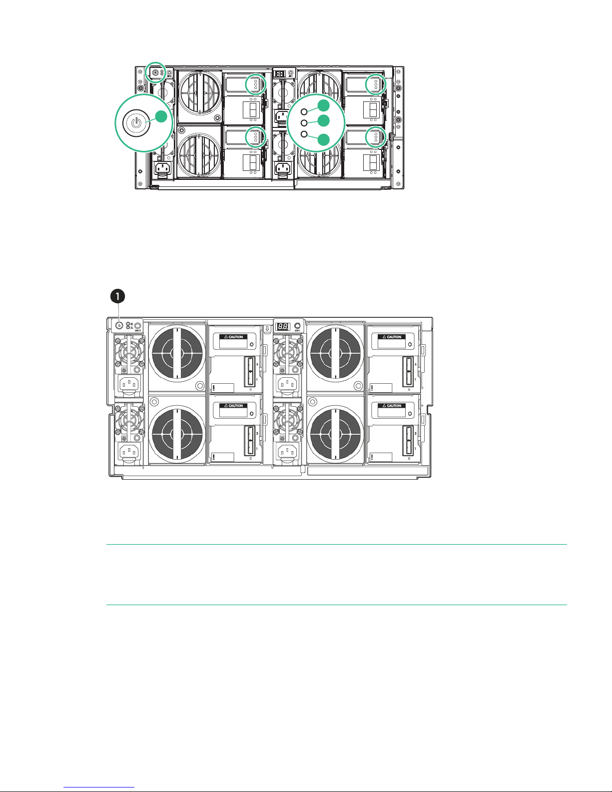
Figure 8 Power button on disk enclosure
2
1
3
4
Powering off the disk enclosure
There are no StoreOnce CLI commands to power off the disk enclosure. Use the Power On/Off
button (1) on the rear of the disk enclosure to power off the unit.
Figure 9 Power button on disk enclosure
After replacing a component
Use the StoreOnce GUI or StoreOnce CLI to check that the firmware on the new component is
correct. See Upgrading BIOS or hardware firmware (page 9).
NOTE: The system reboots after a firmware upgrade, but for some components a cold reboot
is required to complete the process. A message is displayed after the reboot if a cold reboot is
also required. Power down the system, wait the time recommended in the message and then
power on again using the Power On button.
Powering off the disk enclosure 27
Page 28
9 Disk replacement
StoreOnce 4900 Backup RAID configuration
The HPE StoreOnce 4900 server unit has two disks only, which are used for the operating system
and filesystem. If one disk fails, the server unit will continue to operate but the failed disk should
be replaced immediately.
The HPE StoreOnce 4900 Backup system always requires one disk enclosure with base storage
of 11 disks for user data + 4 hot spare disks. These disks are configured in RAID 6 pools, such
that two disks per pool can be lost without loss of backup data. Up to five additional expansion
kits may be added to the disks in the first disk enclosure to increase the backup data capacity,
also RAID 6.
One further disk enclosure can be added to the system, and is connected to the second RAID
controller card. Up to five additional expansion kits may also be added to the disks in the second
disk enclosure to increase the backup data capacity, and the storage expansion model is the
same as for the first disk enclosure.
For instructions on how to connect additional storage by installing a StoreOnce 4900 Backup
44TB or 60TB capacity expansion kit, please see the printed documentation supplied with the
additional storage.
Hot spare disks
There are two hot spare disks in each drawer of the disk enclosure, bays 34 and 35. If a data
disk fails, the hot spare disk is automatically used until the failed disk is replaced. The disk is
only returned to its status of hot spare disk when the data is fully rebuilt on the replacement disk.
The hot spare disks maintain RAID 6 redundancy for the volumes within each drawer when a
drive has failed. However, it is important to replace failed or predictive failing disks as soon as
possible. If more than two disks fail in the same RAID volume, the system will fail and data will
be lost.
Disk bay locations
The following drawing identifies disk bay locations within a drawer.
Figure 10 Disk bay locations
1
2
6
7
3
4
5
8
9
13
14
10
11
12
15
16
20
21
17
18
19
22
23
27
28
24
25
26
29
30
34
35
31
32
33
NOTE: Disk bays 1 to 7 are at the front of the drawer.
28 Disk replacement
Page 29

When monitoring disk status from the StoreOnce GUI, the Location field on the Hardware tree
identifies the bay in which a disk is located. (Expand Storage Clusters to find drives within a
specific drawer and drive enclosure.)
Figure 11 Drives page on StoreOnce GUI
Distributing the disk drives correctly
The initial eleven disks (plus four hot-plug disks) in the disk enclosure are installed and
pre-configured as follows when the HPE StoreOnce 4900 Backup is installed.
Table 5 Disk bays populated at installation
Disk Enclosure 1
Drawer 2Drawer 1
Two spare hot disks in bays 34 and
35.
Two spare hot disks in bays 34 and
35 and eleven disks in slots 23-33.
Initial storage configuration
Disks in HPE StoreOnce 4900 44 TB Capacity Expansion kits are added to specific bays in the
drawers within the disk enclosure according to the sequence in which the disk set is being added.
Each drawer has a label that specifies the sequence in which each set of 11 disks must be
installed. This sequence is mandatory for StoreOnce software support.
Table 6 Populating disk bays with Capacity Expansion kits
Drawer 2Drawer 1
Add eleven disks to slots 23-33Do not change+ Expansion kit 1
Do not changeAdd eleven disks to slots 12-22+ Expansion kit 2
Add eleven disks to slots 12-22Do not change+ Expansion kit 3
Do not changeAdd eleven disks to slots 1-11+ Expansion kit 4
Add eleven disks to slots 1-11Do not change+ Expansion kit 5
Ordering the correct replacement disk for a failed disk
It is important to replace a failed or predictive failed disks as soon as possible. Multiple disk
failures within the same array will result in complete data loss.
Note that ALL enclosures of storage must be working for the system to operate; if the RAID fails
on any one enclosure due to exceeding the maximum amount of failed disks in a pool then ALL
data is lost.
IMPORTANT: HPE strongly recommends replacing a failed disk with a fresh disk from the
factory. Do not substitute a disk from another RAID set.
It is important to identify whether the disk is in the server unit or the attached shelf, because
different disks are used in the two locations and the carriers are different.
Ordering the correct replacement disk for a failed disk 29
Page 30

Always quote the serial number and product number for the enclosure that contains the failed
disk so that support can replace the correct part.
Table 7 Disk types
Part numberWhere usedDisk
653954-001HPE StoreOnce 4900 Backup (2
disks), server unit
HP 1TB 7.2K SAS 2.5" SC Hard Disk
Drive
743405-001HPE StoreOnce 4900 Backup disk
enclosures
HP 4TB 6G SAS Hard Disk Drive
695842-001HPE StoreOnce 2900 Backup (6-12
disks)
ZHP 4TB 6G SAS 7.2K 3.5in MDL
SC HDD
Replacing a hot plug disk in a disk enclosure
Important Safety information
WARNING! To reduce the risk of personal injury or damage to the equipment, ensure that
only one hard drive drawer is extended at a time.
Replacing a hard drive within the enclosure is an online activity, providing the following general
guidelines are observed:
• When the drawer is opened, the cooling fans in the enclosure will run at full-speed. This is
normal.
• Hard drives are sensitive to excessive vibration. Use care when opening and closing the
drawer.
• Never leave the drawer open for any length of time. It should be opened only for maintenance
and storage expansion.
• Verify that the drives are fully seated before closing the drawer.
• The drawer is fully closed when the fans slow down to their normal speed.
• The drawer should be closed with the handle in the released position.
NOTE: Remember to close the handle after closing the drawer
Installing the drives in a StoreOnce disk enclosure
1. If you are using HPE StoreOnce Remote Support on your system, run the following StoreOnce
CLI command to suppress remote event reporting:
system enable remoteeventsuppression "Disk Maintenance"
2. Identify which drive needs replacing and its drawer and bay location. This information may
be provided from SNMP alerts or from the StoreOnce GUI on the Events or Hardware
pages. For example, expand the Hardware tree until you locate the item that has failed.
30 Disk replacement
Page 31

TIP: You may need to expand the Location column to identify the bay to which the drive
belongs. (Port identifies which of the two ports on the RAID controller the disk enclosure is
connected to and Box identifies the drawer.)
You can also use the Turn Beacon LED On button that you can see in above screenshot
to ensure that you have the right disk when opening the drawer.
3. Open the hard drive drawer for the relevant drawer. To extend the drawer (3), pull the handle
up (1) and out (2).
Figure 12 Opening the disk drawer
1
2
3
4. To release the carrier handle (2), press the button (1), and remove the failed drive.
Figure 13 Removing the drive
5. Insert the replacement hard drive (1) and close the carrier handle (2).
Replacing a hot plug disk in a disk enclosure 31
Page 32

6. Close the hard drive drawer. You will hear it click into place when it is securely closed. The
fans will return to normal speed when both drawers are properly closed.
WARNING! Pinch hazard—Keep hands out of front and rear of chassis when closing hard
drive drawers.
CAUTION: To prevent improper cooling and thermal damage, do not operate the disk
enclosure for an extended period with the drawer open.
CAUTION: To prevent improper cooling and thermal damage, do not operate the disk
enclosure unless all bays are populated with either a component or a blank.
7. Use the StoreOnce GUI or StoreOnce CLI to check that the firmware on the new component
is correct.
NOTE: Note the output at command completion. It will advise if you need a system reboot
or a cold reboot to install the new firmware revision successfully.
8. If you are using HPE StoreOnce Remote Support, to return to normal mode after maintenance,
run the StoreOncCLI command:
system disable remoteeventsuppression "Disk Maintenance"
More information
Upgrading BIOS or hardware firmware (page 9)
Rebuilding storage if multiple disks fail and a RAIDset is broken
This section explains how to rebuild your storage in the event of a complete data loss. This should
be done under the guidance of HPE Support.
After the failed disks have been replaced it will be necessary to remove the old filesystem
configuration and rebuild a new one as follows:
1. Use the following StoreOnce CLI to remove all configured storage on the appliance (except
that used by the operating system):
hardware delete storage all
WARNING! This command will completely remove all configured storage, and will run at
any time even if the storage is healthy.
2. This will clean up all filesystem configuration and delete logical drives (LUNs) on all storage
devices.
32 Disk replacement
Page 33

3. After the delete command has completed rebuild the storage system using the following
StoreOnce CLI commands to discover and add storage to the system
hardware discover storage
hardware add storage
This will configure both the storage in the appliance (base storage) and any attached
expansion shelves. Licenses must be present for all attached storage before the command
will complete successfully. If insufficient licenses are available, no storage will be configured.
Rebuilding storage if multiple disks fail and a RAIDset is broken 33
Page 34

10 LEDs on StoreOnce Backup systems
LEDs and StoreOnce GUI
If an LED indicates an error condition, HPE recommends reviewing the StoreOnce Event log for
more information.
For hardware-related errors the Hardware page of the StoreOnce GUI provides valuable
information.
NOTE: All diagrams in this chapter show the unit with the cover plate removed.
34 LEDs on StoreOnce Backup systems
Page 35

HPE StoreOnce 4900 Backup system server
The HPE StoreOnce 4900 Series Backup system consists of a server unit (with two disks) and
one disk enclosure with 15 disks on which storage has already been expanded. It supports
additional disks in the first disk enclosure (44TB Expansion Kits) and connection of an additional
disk enclosure (60TB Capacity Expansion Kit). Storage must be expanded when expansion kits
are added to the base configuration.
Figure 14 Front view of the HPE StoreOnce 4900 Backup server
Off: no network connection or network not configured1. NIC status LED
Steady green: network connected
Flashing green: network activity
Steady green: Hardware is performing correctly2. System Health LED
Flashing amber: degraded condition
Flashing red: critical condition, such as power supply or
fan failure
Steady green: Power connected, device ready to use3. Power On button/LED
Flashing green: performing power on sequence
Steady amber: Device switched off or in hibernation with
power connected
Steady blue: identifies the unit
Off: No power connected
Steady blue identifies the StoreOnce Backup system in
the rack.
4. UID button
Flashing blue: remote management or firmware upgrade
in progress
The HP systems Insight Display LEDs represent the
system board layout and may be useful for troubleshooting.
See the “Maintenance and Service Guide” for more details.
5. System Insight Display
These drives contain the operating system and filesystem.
They are not used for data storage.
6. Hot plug drives
HPE StoreOnce 4900 Backup system server 35
Page 36
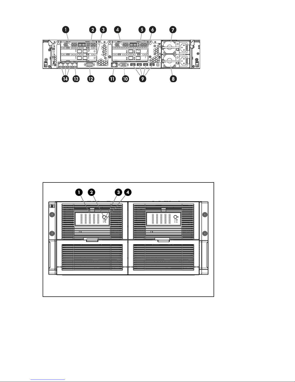
Figure 15 Rear view of the HPE StoreOnce 4900 Backup server
FC card 12.RAID card 11.
RAID card 24.FC card 23.
10GbE card 26.10GbE card 15.
Power supply 28.Power supply 17.
Video/monitor port10.USB ports9.
Serial connector12.iLO4 Management port (do not use for data
connection)
11.
1GbE network ports 2, 3 and 414.1GbE network port 1 (used with Quick Install
option)
13.
HPE StoreOnce 4900 Backup disk enclosure
Figure 16 Front view of the disk enclosure LEDs
Green = The drive is online, but is not currently active.1. Hard drive LEDs Normal mode (UID LED is solid)
Flashing irregularly green = The drive is active and it is
operating normally.
Flashing green (1 Hz) = Do not remove the drive.
Removing the drive may terminate the current operation
and cause data loss. The drive is rebuilding, or it is part
of an array that is undergoing expansion, logical drive
extension, a stripe size migration, or RAID migration.
36 LEDs on StoreOnce Backup systems
Page 37

Flashing amber/green = Drive is configured and indicating
a predictive failure. The drive may also be undergoing a
rebuild, expansion, extension, or migration.
Flashing amber (1 Hz) = A predictive failure alert has been
received for this drive. Replace the drive as soon as
possible.
Amber = Drive failure, link failure, or mismatched
configuration.
Off = The drive is offline, a spare, or not configured as part
of an array.
Green = The drive has been selected by a management
application and it is operating normally.
1. Hard drive LEDs Drive Locate mode (UID LED is
flashing)
Flashing amber (1 Hz) = The drive is not selected and is
indicating a predictive failure.
Flashing amber/green = The drive has been selected by
a management application and is indicating a predictive
failure.
Amber = The drive might or might not be selected and is
indicating drive failure, link failure, or mismatched
configuration.
Off = The drive is not selected.
Blue = UID LED is enabled from the UID button2. UID button/LED
Blue flashing = Item 1 is in locate mode
Off = UID LED is disabled
Green = System health is good3. Internal health LED
Off = System is off
Amber = Enclosure requires service check: I/O, fan and
power supply LEDs, and AC power cables to power
supplies.
4. GSI LED
Off = Enclosure is functioning normally.
HPE StoreOnce 4900 Backup disk enclosure 37
Page 38

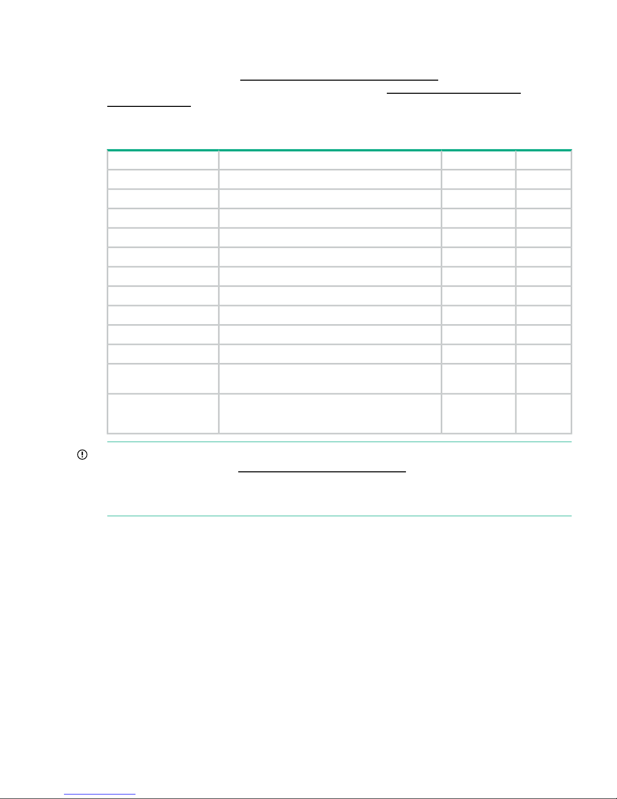
Figure 17 Rear view of the disk enclosure LEDs
StatusDescriptionItem
Green = OnPower On/Standby button and
system power LED
1
Amber = Standby (auxiliary power present)
Off = Off
Green = System health is good.Internal Health LED2
Off = System is off.
Amber = Enclosure requires service check: I/O, fan and power
supply LEDs, and AC power cables to power supplies.
GSI LED*3
Off = Enclosure is functioning normally.
Blue = UID LED is enabled from the UID button.UID button/LED (Drawer 2)4
Blue flashing = System is in hard drive locate mode or an enclosure
firmware update is in progress.
Off = UID LED is disabled.
Green = Power on and power supply functioning properlyPower supply LED5
Off = One or more of the following conditions exists:
• System powered off
• AC power unavailable
• Power supply failed
• Power supply exceeded current limit
Green = Normal operationSystem fan LED6
Amber flashing = Fault
Off = Fan unseated from connector or
Green = System activityI/O module LED7
Amber = Fault
Off = Enclosure is powered off.
1 = SES overall warning7-segment display*8
38 LEDs on StoreOnce Backup systems
Page 39

StatusDescriptionItem
2 = Temperature sensor warning
3 = Cooling fan warning
4 = Power supply warning
5 = Host GSI enabled
6 = I/O PIC upgrade needed
7 = Power supply PIC upgrade needed
8 = CPLD upgrade needed
9 = Standby heartbeat failure
10 = Remote I/O module heartbeat failure
11 = Enclosure thermal shutdown imminent
12 = Enclosure thermal shutdown occurred
13 = Enclosure management bus failure, false fan failures may
occur
14 = Signal integrity errors detected
15 = Power supply PIC communications error
16 = Unsupported backplane detected
Blue = UID LED is enabled from the UID buttonUID button/LED (Drawer 1)9
Blue flashing = System is in hard drive locate mode or an enclosure
firmware update is in progress.
Off = UID LED is disabled.
* If the GSI is amber, the system needs service. Activate the associated drawer UID button to
view any GSI error codes on the rear display.
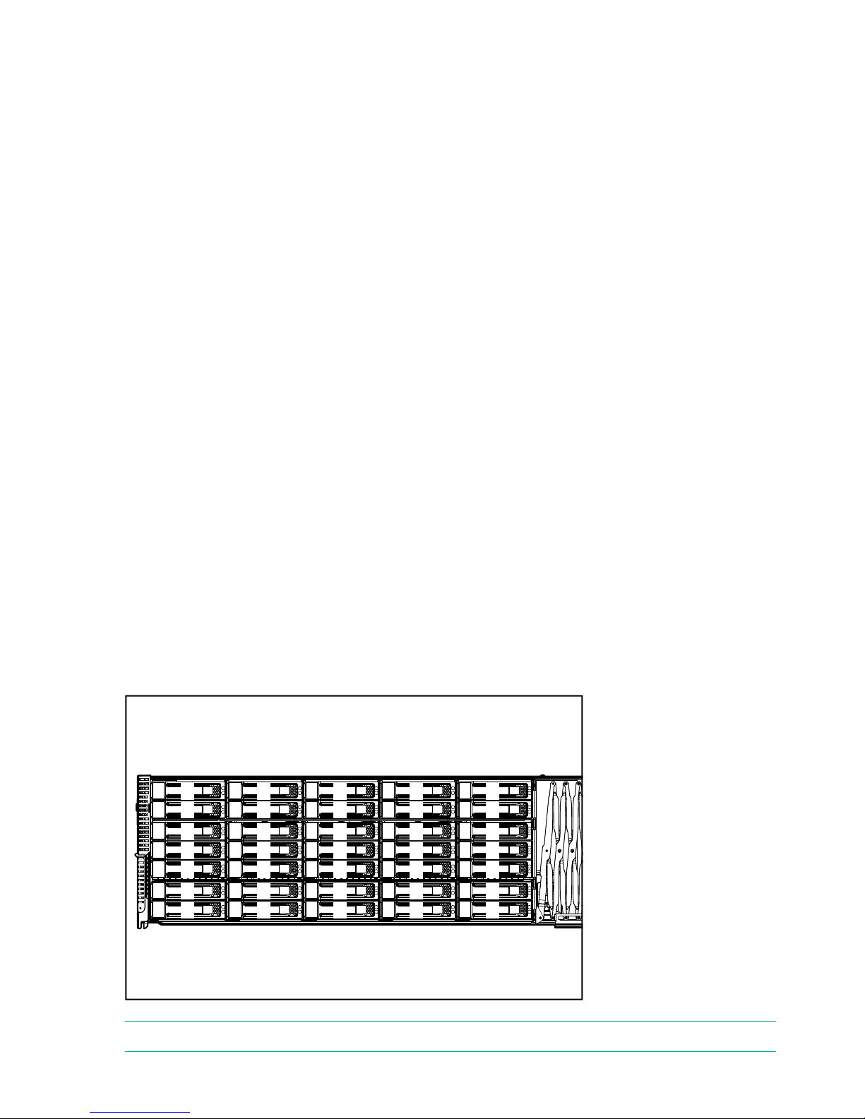
Rear view of the disk enclosure
The following figure illustrates the components that are accessible from the rear of the disk
enclosure.
Figure 18 Rear view of the disk enclosure
Drawer 2, IO module A2.Power supply1.
Drawer 2, IO module A, Port 24.Drawer 2, IO module A, Port 13.
HPE StoreOnce 4900 Backup disk enclosure 39
Page 40

Drawer 1, IO module A6.Power supply5.
Drawer 1, IO module A, Port 28.Drawer 1, IO module A, Port 17.
Drawer 1, IO module B, Port 210.Drawer 1, IO module B, Port 19.
Power supply12.Drawer 1, IO module B11.
Drawer 2, IO module B, Port 214.Drawer 2, IO module B, Port 113.
Power supply16.Drawer 2, IO module B15.
40 LEDs on StoreOnce Backup systems
Page 41

Hot-plug drive LEDs
HPE StoreOnce 4900 Backup server units
The hot-plug drives in server units are illustrated below. The disks in the expansion shelves have
a different carrier.
Figure 19 Drive LEDs in server unit
Solid blue = The drive is being identified by a host application.1. Locate
Flashing blue = The drive carrier firmware is being updated or requires an update.
Off = No drive activity2. Activity ring
Rotating green = Drive activity
Solid white = Do not remove the drive. Removing the drive causes one or more of the
logical drives to fail.
3. Do not remove
Off = Removing the drive will not cause a logical drive to fail.
Off = The drive is not configured by a RAID controller.4. Drive status
Solid green = The drive is a member of one or more logical drives.
Flashing green = The drive is rebuilding or performing a RAID migration, stripe size
migration, capacity expansion, or logical drive extension.
Flashing amber/green = The drive is a member of one or more logical drives and predicts
the hard drive will fail.
Flashing amber = The drive is not configured and predicts the hard drive will fail.
Solid amber = The drive has failed.
Disks in HPE StoreOnce 4900 Backup disk enclosure
There are two hot spare disks in each drawer of the disk enclosure, bays 34 and 35. If a data
disk fails, the hot spare disk is automatically used until the failed disk is replaced. The disk is
only returned to its status of hot spare disk when the data is fully rebuilt on the replacement disk.
The hot spare disks provide RAID 6 redundancy for the volumes within each drawer after a failure
and rebuild has occurred. However, it is important to replace failed or predictive failing disks as
soon as possible. If more than two disks fail in the same pool, the system will fail and data will
be lost.
Hot-plug drive LEDs 41
Page 42

Figure 20 Drive in enclosure LEDs
Fault/UID LED (amber/blue)1
Online LED (green)2
Table 8 Hard disk LED sequences
InterpretationFault/UID LED (amber/blue)Online Activity LED (green)
The drive has failed, or a predictive
failure alert has been received for this
Alternating amber and blueOn, off or flashing
drive; it also has been selected by a
management application.
The drive is operating normally, and it
has been selected by a management
application.
Steady blueOn, off or flashing
A predictive failure alert has been
received for this drive. Replace the
drive as soon as possible.
Amber flashing regularlyOn
The drive is online, but it is not
currently active.
OffOn
Do not remove the drive. Removing
a drive may terminate the current
Amber flashing regularlyFlashing regularly (1 Hz)
operation and cause data loss. The
drive is part of an array that is
undergoing capacity expansion or a
stripe size migration, but a predictive
failure alert has been received for this
drive. To minimize the risk of data loss,
do not replace the drive until the
expansion or migration is complete.
Do not remove the drive. Removing
a drive may terminate the current
OffFlashing regularly (1 Hz)
operation and cause data loss. The
drive is rebuilding, or it is part of an
array that is undergoing array
expansion, logical drive extension, a
42 LEDs on StoreOnce Backup systems
Page 43
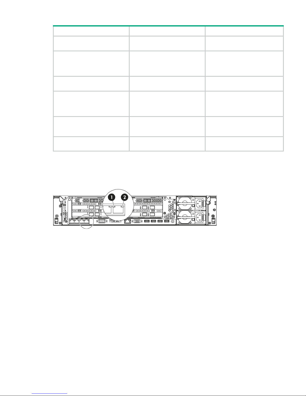
Table 8 Hard disk LED sequences (continued)
InterpretationFault/UID LED (amber/blue)Online Activity LED (green)
stripe size migration, or RAID
migration.
The drive is active, but a predictive
failure alert has been received for this
Amber flashing regularly (1 Hz)Flashing irregularly
drive. Replace the drive as soon as
possible.
The drive is active and it is operating
normally.
OffFlashing irregularly
A critical fault condition has been
identified for this drive and the
OffOff
controller has placed it offline. Replace
the drive as soon as possible.
A predictive failure alert has been
received for this drive. Replace the
drive as soon as possible.
Amber flashing regularlyOff
The drive is offline, a spare, or not
configured as part of an array.
OffOff
1 Gbit ethernet port LEDs
The 1 Gbit ethernet LAN ports have two LEDs on the rear of the HPE StoreOnce Backup system.
Figure 21 1 Gbit ethernet LAN port LEDs
Steady green: The LAN connection is using 10 Mbps/100
Mbps link.
1. LAN network speed LED indicator
Steady amber: The LAN connection is using a 1 Gbit
ethernet link.
Off: No connection.
Flashing green: Ongoing network data activity.2. LAN activity status LED indicator
Off: No network data activity or no connection.
10 Gbit ethernet card LEDs
Each 10 Gbit ethernet card has two LEDs, as illustrated below.
1 Gbit ethernet port LEDs 43
Page 44

Figure 22 10 Gbit ethernet card LEDs (example shows HPE StoreOnce 4700 Backup)
Off: No link to the adapter is established. The adapter is
not receiving power or the cable connection is faulty
1. Link
On (yellow): Link to the adapter is established. The adapter
is receiving power and the cable connection is good.
Flashing green: Ongoing network data activity. The adapter
is sending or receiving network data at up to 10 Gb/s
2. Activity
Off: No network data activity or no connection.
Fibre Channel card LEDs
There are three LEDs adjacent to each FC port.
Table 9 FC card LEDs
ActivityAmber LEDGreen LEDYellow LED
Power Off (OK)OffOffOff
Power on before or after software initialization.
Awaiting HBA software initialization.
OnOnOn
Power on after software initialization. Link not
initialized.
FlashingFlashingFlashing
Software fault (OK)Alternately flashingAlternately flashingAlternately flashing
Connected at: 2 Gb/sOnOffOff
Activity at 2 Gb/s (OK)FlashingOffOff
Connected at 4 Gb/sOffOnOff
Activity at 4 Gb/s (OK)OffFlashingOff
Connected at 8 Gb/sOffOffOn
Activity at 8 Gb/sOffOffFlashing
44 LEDs on StoreOnce Backup systems
Page 45

11 The QR ISO image
The StoreOnce QR ISO image
In the rare occurrence of a complete system failure, it may be necessary to reinstall the product
software. This task is normally carried out on the recommendation and under the supervision of
HPE Support.
CAUTION: The Quick Restore process will delete all stored data and configuration settings
returning your product to factory default settings.
Download Quick Restore ISO Image
The StoreOnce Quick Restore ISO Image is used to install the StoreOnce software image onto
the StoreOnce appliance disks.
1. Go to the HPE Support page at http://www.hpe.com/support/hpesc, search on your product
and select HPE StoreOnce Backup.
2. Under Download Options, select the Get drivers, software & firmware link.
3. To display a list of all available downloads, select OS Independent under Operating
Systems.
4. The QR ISO image is under Software. The HPE USB Key Utility for Windows can be
downloaded from the Utility option.
5. Click Obtain Software and select the QR ISO image appropriate to your product. You will
be required to sign in with HPE Passport to download the QR ISO image, and can create
an HPE Passport account when you first access the site.
6. Create the physical QR media.
Use the HPE USB Key Utility for Windows to copy the ISO image to a USB key using a
Windows PC.
Alternatively, use the iLO4 ISO mounting utility to mount the virtual CD-ROM over iLO.
IMPORTANT: HPE recommends that you label the new media for ease of identification.
Create a bootable QR USB Stick
Use the HPE USB Key Utility for Windows to copy the ISO image to an 8 GB USB key using a
Windows PC.
NOTE: USB 3 keys are not supported.
1. From the Utility link on your product’s Download page, download the Smart Component to
a directory on your hard drive and change to that directory. The downloaded file is a
self-extracting executable with a filename based on the Smart Component Number. From
that drive and directory, execute the downloaded file.
2. After installation, the utility will place a shortcut in HPE System Tools in the Programs start
menu folder. To make your drive key bootable and copy the ISO image to it:
• Place your HPE USB drive key (minimum size 8 GB flash stick) in an available USB
port.
• Select the HPE USB Key Utility shortcut in the HPE System Tools folder.
• Complete each step presented by the application.
3. Once all steps are completed, remove the USB stick from the Windows PC.
The StoreOnce QR ISO image 45
Page 46

Delete storage
Before running QR, it is advisable to remove all configured storage on the appliance. If you do
not remove all configured storage, you may get error messages during QR, reporting the presence
of Alien LUNs.
1. Use the following StoreOnce CLI to remove all configured storage on the appliance (except
that used by the operating system):
hardware delete storage all
2. This command will clean up all filesystem configuration and delete logical drives (LUNs) on
all storage devices.
Boot the appliance and install the StoreOnce software
Make sure that power, network, keyboard and monitor, and all expansion enclosures are attached
to the StoreOnce appliance, then insert the QR USB stick into a USB port and power on the
system.
After the system powers up and completes self-tests, it will boot from the USB key and launch
the Linux installation process.
NOTE: An error will be displayed: [Firmware Bug]: the BIOS has corrupted hw-PMU
resources (MSR 38d is 330). This error does not have any effect on the StoreOnce solution
and is an expected output during QR. The customer or support engineer does not need to take
any action.
After a few seconds, a boot splash screen will appear offering the choice of Restore (R) or Exit
(E). To continue to the installation process, press R.
A warning will now be displayed indicating that all data will be lost after entering “yes”. THIS IS
THE LAST CHANCE TO EXIT THE INSTALL PROCESS WITHOUT DATA LOSS.
Enter “yes” to continue.
The installation process will now continue and will:
1. Delete the existing logical storage configuration on the appliance server disks.
2. Create a new logical storage partition; depending on the appliance type this may be a pair
of mirrored disks or a LUN stripe across all disks in the appliance.
3. Install the Operating System and appliance software on the system.
4. After installation completes, you will be prompted to remove the USB stick and reboot. To
reboot the system, press a key.
5. During the reboot process, the system will perform an install process and return to the login
prompt. During this sequence, you may need to answer questions presented on the console
screen.
Performing a configuration restore
This process is normally carried out after a quick restore (QR) or if a replacement appliance has
been received. It restores the appliance to the same state as it was when the configuration file
was created. It is important that there are no configured backup target devices on the appliance.
IMPORTANT: During this process, you may be prompted to provide the Cluster ID. The Cluster
ID is the same as the System ID that can be found on the Device Management page of the
StoreOnce Management Console. Its value is assigned in the factory set up process and is a
12–character string in the format HP<SerialNumber of Appliance>.
46 The QR ISO image
Page 47

This process requires the latest configuration files that should have been saved and copied locally
to the local system. You will require the following files:
• <config_filename>.zip
• <config_filename>.txt
• <keystore_filename>.kms (if you have installed the Security Pack license and configured
Data at Rest Encryption on any VTL libraries, NAS shares, or Catalyst stores)
1. Check the Cluster ID against the value shown in the configuration text file,
<config_filename>.txt, using the StoreOnce CLI command:
system show config
2. If necessary reset the Cluster ID of the cluster to the ID of the original appliance, the cluster
ID is shown in the configuration text file, run the command:
system set cluster <cluster_id>
This step may not be necessary if there has been no replacement hardware or if the serial
number of the original appliance has been copied to the BIOS settings of the replacement
appliance.
IMPORTANT: You can only restore the configuration file to an appliance that has the
same cluster ID as the one from which the configuration was taken.
3. Using the latest <config_filename>.txt file, manually apply all of the settings within
this configuration text file using the StoreOnce CLI commands and instructions exactly as
shown. This will ensure that the customer configuration is restored to its previous
configuration. It is important that this is done manually before attempting to restore the device
settings automatically.
NOTE: If the product has additional storage connected, ensure that Capacity Upgrade Kit
licenses are applied.
4. Reconfigure the storage for the appliance using the commands:
hardware discover storage
hardware add storage
5. Monitor the expansion using the following command:
system show status
This command will return either of the following after an add command has been sent:
• Adding X,XXXGB...
• Formatted XXGB, which means that the storage and file system has been configured
and is ready for use. Parity initialization may still be in progress.
The following output is an example; the values shown may not match your appliance-specific
values.
# system show status
Status
-----Formatted 15,070.76GB
Service Sets Status Notes
------------ ------ ----Set 1 Running
Performing a configuration restore 47
Page 48

NOTE: The addition of storage will take a minimum of two hours to complete. You will not
be able to complete the next steps until storage is formatted.
6. Using an SFTP client copy the saved configuration zip file to the config folder on the
appliance.
• Using Linux
sftp Admin@<IP_address>
cd config
put <config_filename>.zip
exit sftp
• Using a Windows sftp client
Ensure that the File Protocol is set to SFTP, not SCP.
Login as Admin.
Copy <config_filename>.zip to config.
7. Use the following StoreOnce CLI command to check that the file has been uploaded:
config show list
8. Run the StoreOnce CLI command:
config restore devices <config_filename>
This command will restore device settings for the appliance.
9. After configuration recovery, backups can be configured and replication mappings
re-established to reverse replicate data back to the appliance (see replication information
in the user guide).
48 The QR ISO image
Page 49

12 Support and other resources
Accessing Hewlett Packard Enterprise Support
• For live assistance, go to the Contact Hewlett Packard Enterprise Worldwide website:
www.hpe.com/assistance
• To access documentation and support services, go to the Hewlett Packard Enterprise Support
Center website:
www.hpe.com/support/hpesc
Information to collect
• Technical support registration number (if applicable)
• Product name, model or version, and serial number
• Operating system name and version
• Firmware version
• Error messages
• Product-specific reports and logs
• Add-on products or components
• Third-party products or components
Accessing updates
• Some software products provide a mechanism for accessing software updates through the
product interface. Review your product documentation to identify the recommended software
update method.
• To download product updates, go to either of the following:
Hewlett Packard Enterprise Support Center Get connected with updates page:
www.hpe.com/support/e-updates
◦
◦ Software Depot website:
www.hpe.com/support/softwaredepot
• To view and update your entitlements, and to link your contracts and warranties with your
profile, go to the Hewlett Packard Enterprise Support Center More Information on Access
to Support Materials page:
www.hpe.com/support/AccessToSupportMaterials
IMPORTANT: Access to some updates might require product entitlement when accessed
through the Hewlett Packard Enterprise Support Center. You must have an HP Passport
set up with relevant entitlements.
Websites
LinkWebsite
www.hpe.com/info/enterprise/docsHewlett Packard Enterprise Information Library
www.hpe.com/support/hpescHewlett Packard Enterprise Support Center
Accessing Hewlett Packard Enterprise Support 49
Page 50
LinkWebsite
www.hpe.com/assistanceContact Hewlett Packard Enterprise Worldwide
www.hpe.com/support/e-updatesSubscription Service/Support Alerts
www.hpe.com/support/softwaredepotSoftware Depot
www.hpe.com/support/selfrepairCustomer Self Repair
www.hpe.com/info/insightremotesupport/docsInsight Remote Support
www.hpe.com/info/hpux-serviceguard-docsServiceguard Solutions for HP-UX
www.hpe.com/storage/spockSingle Point of Connectivity Knowledge (SPOCK)
nl
Storage compatibility matrix
www.hpe.com/storage/whitepapersStorage white papers and analyst reports
Remote Support
Remote support is available with supported devices as part of your warranty or contractual support
agreement. It provides intelligent event diagnosis, and automatic, secure submission of hardware
event notifications to Hewlett Packard Enterprise, which will initiate a faster and more accurate
resolution of any issues based on the service level for your product. Hewlett Packard Enterprise
strongly recommends that you register your device for remote support.
The preferred HPE Remote Support solution for StoreOnce products is Service Tools and
Technical Support (STaTS), however Insight Remote Support is also available.
• Service Tools and Technical Support (STaTS): HPE Remote Support monitors StoreOnce
appliances and allows the appliance to contact Hewlett Packard Enterprise proactively if
issues arise on the system. Site-specific data is used both proactively and reactively with
real-time monitoring and information extraction tools.
For information on Remote Support via STaTS, go to the following website: http://
www.hpe.com/partners/StoreOnceRemote
• StoreFrontRemote Manager: StoreFrontRemote Manager is a reporting tool, where
customers are able to track their specific systems, showing additional reporting and analysis.
Registration is simple and can allow customers to view parametric information collected
about the configuration and performance of their products.
• Insight RS: For information and device support details for Insight RS, go to the following
website:
http://www.hpe.com/info/insightremotesupport/docs
Customer self repair
Hewlett Packard Enterprise customer self repair (CSR) programs allow you to repair your product.
If a CSR part needs to be replaced, it will be shipped directly to you so that you can install it at
your convenience. Some parts do not qualify for CSR. Your Hewlett Packard Enterprise authorized
service provider will determine whether a repair can be accomplished by CSR.
For more information about CSR, contact your local service provider or go to the CSR website:
www.hpe.com/support/selfrepair
Documentation feedback
Hewlett Packard Enterprise is committed to providing documentation that meets your needs. To
help us improve the documentation, send any errors, suggestions, or comments to Documentation
Feedback (docsfeedback@hpe.com). When submitting your feedback, include the document
title, part number, edition, and publication date located on the front cover of the document. For
50 Support and other resources
Page 51

online help content, include the product name, product version, help edition, and publication date
located on the legal notices page.
Documentation feedback 51
Page 52
A Warranty and regulatory information
For important safety, environmental, and regulatory information, see Safety and Compliance
Information for Server, Storage, Power, Networking, and Rack Products, available at
www.hpe.com/support/Safety-Compliance-EnterpriseProducts.
Warranty information
HPE ProLiant and x86 Servers and Options
www.hpe.com/support/ProLiantServers-Warranties
HPE Enterprise Servers
www.hpe.com/support/EnterpriseServers-Warranties
HPE Storage Products
www.hpe.com/support/Storage-Warranties
HPE Networking Products
www.hpe.com/support/Networking-Warranties
Regulatory information
Belarus Kazakhstan Russia marking
Manufacturer and Local Representative Information
Manufacturer information:
• Hewlett Packard Enterprise Company, 3000 Hanover Street, Palo Alto, CA 94304 U.S.
Local representative information Russian:
• Russia:
• Belarus:
• Kazakhstan:
52 Warranty and regulatory information
Page 53
Local representative information Kazakh:
• Russia:
• Belarus:
• Kazakhstan:
Manufacturing date:
The manufacturing date is defined by the serial number.
CCSYWWZZZZ (serial number format for this product)
Valid date formats include:
• YWW, where Y indicates the year counting from within each new decade, with 2000 as the
starting point; for example, 238: 2 for 2002 and 38 for the week of September 9. In addition,
2010 is indicated by 0, 2011 by 1, 2012 by 2, 2013 by 3, and so forth.
• YYWW, where YY indicates the year, using a base year of 2000; for example, 0238: 02 for
2002 and 38 for the week of September 9.
Turkey RoHS material content declaration
Ukraine RoHS material content declaration
Regulatory information 53
 Loading...