


 Loading...
HP Scanjet N9120
Service Manual

HP Scanjet N9120
Service Manual
Copyright information
© 2008 Copyright Hewlett-Packard
Development Company, L.P.
Reproduction, adaptation, or translation without prior written permission is prohibited, except as allowed under the copyright laws.
The information contained herein is subject to change without notice.
The only warranties for HP products and services are set forth in the express warranty statements accompanying such products and services. Nothing herein should be construed as constituting an additional warranty. HP shall not be liable for technical or editorial errors or omissions contained herein.
Part number L2683-90022
Edition 1, 7/2008
Safety information
WARNING!
Potential Shock Hazard
Always follow basic safety precautions when using the product to reduce risk of injury from fire or electric shock.
Read and understand all instructions in the user guide.
Observe all warnings and instructions marked on the product.
Use only a grounded electrical outlet when connecting the product to a power source. If you do not know whether the outlet is grounded, check with a qualified electrician.
Do not touch the contacts on the end of any of the sockets on the product. Replace damaged cords immediately.
Unplug the product from wall outlets before cleaning.
Do not install or use the product near water or when you are wet.
Install the product securely on a stable surface.
Install the product in a protected location where no one can step on or trip over the power cord and where the power cord will not be damaged.
Trademark credits
Microsoft(r), Windows(r), and Windows(r) XP are U.S. registered trademarks of Microsoft Corporation.
Windows Vista® is either a registered trademark or trademark of Microsoft Corporation in the United States and/or other countries.
ENERGY STAR and the ENERGY STAR mark are registered U.S. marks.

Table of contents
1 Product basics |
|
Quick access to product information .................................................................................................... |
2 |
Product basics ...................................................................................................................................... |
3 |
Product features .................................................................................................................. |
3 |
Product walkaround ............................................................................................................. |
4 |
Front and right-side view ..................................................................................... |
4 |
Back view ............................................................................................................ |
5 |
Side view (left) ..................................................................................................... |
5 |
Model and serial numbers ................................................................................... |
6 |
Control-panel walkaround .................................................................................................... |
7 |
Supported product software ................................................................................................. |
8 |
Supported operating systems ............................................................................. |
8 |
Supported scanner drivers .................................................................................. |
8 |
Supported scanner-management software ......................................................... |
8 |
System requirements ........................................................................................................................... |
9 |
Paper handling ................................................................................................................................... |
10 |
ADF specifications ............................................................................................................. |
10 |
Media specifications .......................................................................................................... |
10 |
Media to avoid ................................................................................................................... |
11 |
2 Installation and configuration |
|
Prepare the site .................................................................................................................................. |
14 |
Unpack the device .............................................................................................................................. |
15 |
Install the software ............................................................................................................................. |
19 |
3 Manage and maintain |
|
Manage supplies ................................................................................................................................ |
22 |
HP Scanner Tools Utility scanner maintenance information .............................................. |
22 |
Parts life expectancy .......................................................................................................... |
22 |
Clean the product ............................................................................................................................... |
23 |
Clean the exterior .............................................................................................................. |
23 |
Clean the ADF ................................................................................................................... |
24 |
Clean the scanner glass .................................................................................................... |
27 |
Clean the fan filters ............................................................................................................ |
28 |
ENWW |
iii |
4 Theory of operation |
|
Basic operation ................................................................................................................................... |
30 |
Modes and control-panel indicators ................................................................................................... |
31 |
Circuit board assemblies .................................................................................................................... |
32 |
Fans ................................................................................................................................................... |
33 |
ADF feed system ................................................................................................................................ |
34 |
Sensors .............................................................................................................................. |
34 |
Motors ................................................................................................................................ |
35 |
Service block diagram ........................................................................................................................ |
36 |
5 Removal and replacement |
|
Removal and replacement strategy .................................................................................................... |
38 |
General cautions during removal and replacement ........................................................... |
38 |
Electrostatic discharge ....................................................................................................... |
38 |
Required tools .................................................................................................................... |
39 |
Cleaning supplies .............................................................................................................. |
39 |
Screws and fasteners ........................................................................................................ |
39 |
Before performing service .................................................................................................. |
39 |
After performing service ..................................................................................................... |
40 |
User-replaceable parts ....................................................................................................................... |
41 |
Imprinter cartridge .............................................................................................................. |
42 |
Fan filters ........................................................................................................................... |
44 |
ADF base reflector ............................................................................................................. |
45 |
Reinstall the ADF base reflector ....................................................................... |
46 |
Pickup-roller assembly ....................................................................................................... |
47 |
Reinstall the pickup-roller assembly .................................................................. |
48 |
Separation-pad assembly .................................................................................................. |
49 |
Reinstall the separation-pad assembly ............................................................. |
50 |
External covers ................................................................................................................................... |
51 |
Scanner control-panel cover .............................................................................................. |
52 |
Scanner back-filter cover ................................................................................................... |
53 |
Scanner right-filter cover .................................................................................................... |
53 |
ADF front cover .................................................................................................................. |
54 |
ADF back cover ................................................................................................................. |
57 |
Scanner back cover ........................................................................................................... |
59 |
Automatic document feeder FRUs ..................................................................................................... |
60 |
Automatic document feeder (ADF) .................................................................................... |
62 |
Reinstall the ADF .............................................................................................. |
66 |
ADF height adjustment ...................................................................................... |
70 |
NVRAM data management ............................................................................... |
73 |
Repair menu ..................................................................................... |
73 |
Repair menu options ........................................................................ |
74 |
Replacement scenarios .................................................................... |
75 |
iv |
ENWW |
NVRAM data file examples ............................................................... |
82 |
NVRAM content adjustment ............................................................. |
83 |
Download factory NVRAM data ........................................................ |
84 |
Backup current NVRAM data ........................................................... |
87 |
Repair NVRAM data ......................................................................... |
89 |
Adjust NVRAM counter items ........................................................... |
94 |
Align the ADF .................................................................................................... |
96 |
Create the factory calibration data for ADF-A ................................................... |
99 |
ADF motor fan ................................................................................................................. |
101 |
ADF carriage fan .............................................................................................................. |
102 |
ADF input-tray lift-motor assembly .................................................................................. |
103 |
ADF exit-motor assembly ................................................................................................ |
104 |
ADF feed-motor assembly ............................................................................................... |
108 |
Reinstall the ADF feed-motor drive belt .......................................................... |
110 |
Reinstall the ADF feed-motor assembly .......................................................... |
111 |
ADF pick-motor assembly ................................................................................................ |
114 |
Reinstall the ADF pick-motor assembly .......................................................... |
116 |
Upper multi-pick sensor PCA ........................................................................................... |
119 |
Lower multi-pick sensor PCA ........................................................................................... |
121 |
ADF controller PCA ......................................................................................................... |
123 |
Imprinter PCA .................................................................................................................. |
125 |
Reinstall the imprinter PCA ............................................................................. |
126 |
Input-tray sensor .............................................................................................................. |
129 |
Flatbed scan position sensor ........................................................................................... |
130 |
Reinstall the flatbed scan position sensor ....................................................... |
131 |
Exit 1 sensor .................................................................................................................... |
133 |
Exit 2 sensor .................................................................................................................... |
134 |
Pick-up roller sensor ........................................................................................................ |
135 |
Elevator arm sensor ......................................................................................................... |
137 |
Background solenoid sensor ........................................................................................... |
138 |
Paper-present sensor ...................................................................................................... |
139 |
Registration sensor .......................................................................................................... |
140 |
Jam door 1 sensor ........................................................................................................... |
141 |
Jam door 2 sensor ........................................................................................................... |
142 |
Jam door 3 sensor ........................................................................................................... |
143 |
Imprinter paper-present sensor ....................................................................................... |
144 |
ADF scan position sensor ................................................................................................ |
146 |
ADF bottom corner outer paper path guide ..................................................................... |
147 |
ADF bottom corner inner paper path guide ..................................................................... |
149 |
ADF cal-strip assembly .................................................................................................... |
150 |
Reinstall the cal-strip assembly ....................................................................... |
152 |
ADF exit inner paper path guide ...................................................................................... |
156 |
ADF top corner inner paper path guide ........................................................................... |
159 |
Lower multi-pick sensor cover ......................................................................................... |
160 |
ENWW |
v |
Flatbed scan position sensor arm .................................................................................... |
162 |
Reinstall the flatbed scan position sensor arm ................................................ |
163 |
Exit 1 sensor arm ............................................................................................................. |
165 |
Exit 2 sensor arm ............................................................................................................. |
166 |
Paper-present-sensor arm ............................................................................................... |
168 |
Input-tray-elevator arm .................................................................................................... |
169 |
Registration sensor arm ................................................................................................... |
172 |
Scan position sensor arm ................................................................................................ |
174 |
Pick-up roller spring ......................................................................................................... |
175 |
Separation-pad spring ..................................................................................................... |
176 |
ADF input-tray assembly ................................................................................................. |
177 |
ADF output tray ................................................................................................................ |
179 |
Reinstall the ADF output tray .......................................................................... |
181 |
Pickup-roller cover ........................................................................................................... |
183 |
ADF hinge limiters ........................................................................................................... |
185 |
ADF jam door 3 ................................................................................................................ |
186 |
Paper present sensor and imprinter PCA holder ............................................................. |
188 |
ADF shingle wall .............................................................................................................. |
190 |
A4 paper-stop .................................................................................................................. |
193 |
ADF background-solenoid assembly ............................................................................... |
194 |
Reinstall the ADF background-solenoid assembly .......................................... |
197 |
Imprinter carriage and FFC .............................................................................................. |
199 |
Flatbed scanner FRUs ..................................................................................................................... |
201 |
Flatbed ............................................................................................................................. |
202 |
Scanner carriage-motor fan ............................................................................................. |
203 |
Scanner carriage fan ....................................................................................................... |
206 |
Scanner carriage motor ................................................................................................... |
208 |
Control-panel PCA ........................................................................................................... |
211 |
Scanner controller PCA ................................................................................................... |
213 |
Power-supply PCA ........................................................................................................... |
216 |
Scanner-glass assembly .................................................................................................. |
220 |
ADF power-cable assembly ............................................................................................. |
221 |
Carriage-motor cable ....................................................................................................... |
223 |
Power switch and power receptacle assembly ................................................................ |
224 |
6 Solve problems |
|
Troubleshooting process .................................................................................................................. |
228 |
Pre-troubleshooting checklist ........................................................................................................... |
229 |
Basic troubleshooting checks ........................................................................................................... |
230 |
Power-on checks ............................................................................................................. |
231 |
LED diagnostics .............................................................................................. |
232 |
Check the USB connection ............................................................................. |
233 |
Uninstall and then reinstall the HP Scanjet utilities ......................................... |
233 |
vi |
ENWW |
Control-panel buttons ...................................................................................... |
234 |
Control-panel buttons diagnostics .................................................. |
234 |
Locked control-panel buttons ......................................................... |
234 |
Troubleshooting diagnostic software ................................................................................................ |
235 |
Main screen ..................................................................................................................... |
235 |
Scan dialog box ............................................................................................... |
237 |
Sensor check dialog box ................................................................................. |
239 |
Control panel check dialog box ....................................................................... |
244 |
ADF feed test dialog box ................................................................................. |
246 |
Actuators dialog box ........................................................................................ |
248 |
NVRAM dialog box .......................................................................................... |
251 |
Update dialog box ........................................................................................... |
253 |
Repair menu .................................................................................................... |
254 |
Version information dialog box ........................................................................ |
255 |
Diagrams ......................................................................................................................... |
256 |
Component locator diagrams .......................................................................... |
256 |
Major components .......................................................................... |
256 |
ADF motors and fans ...................................................................... |
258 |
Printed circuit assemblies ............................................................... |
260 |
Image-quality troubleshooting tools ................................................................................. |
262 |
Repetitive-image-defect ruler .......................................................................... |
262 |
Computer-display error messages ................................................................................................... |
263 |
Computer-display error messages ................................................................................... |
263 |
Solve paper-handling problems ........................................................................................................ |
267 |
Jams ................................................................................................................................ |
267 |
Common causes of jams ................................................................................. |
267 |
Solve common ADF jams ................................................................................ |
268 |
Clear jams from the ADF ................................................................................. |
269 |
The bottom of the scanned image is cut off ..................................................................... |
272 |
Scan extra long documents ............................................................................. |
272 |
Disable misfeed (multipick) detection .............................................................................. |
272 |
ADF does not feed paper ................................................................................................. |
273 |
Solve image-quality problems .......................................................................................................... |
274 |
Image defects .................................................................................................................. |
274 |
Set the background color for scans from the ADF ........................................................... |
276 |
Filter out color from a document (color dropout) .............................................................. |
277 |
Solve performance problems ........................................................................................................... |
278 |
Solve connectivity problems ............................................................................................................. |
281 |
Solve direct-connect problems ........................................................................................ |
281 |
7 Parts and diagrams |
|
Ordering parts and supplies ............................................................................................................. |
284 |
Service part numbers ....................................................................................................................... |
285 |
ENWW |
vii |
HP Scanjet N9120 documentation ................................................................................... |
285 |
Imprinter cartridges .......................................................................................................... |
285 |
Power Cords .................................................................................................................... |
286 |
Maintenance kits .............................................................................................................. |
286 |
Field replaceable units (FRUs) ........................................................................................ |
287 |
How to use the parts diagrams and lists .......................................................................................... |
289 |
ADF components .............................................................................................................................. |
290 |
Flatbed scanner assemblies ............................................................................................................. |
318 |
Alphabetical parts list ....................................................................................................................... |
336 |
Numerical parts list ........................................................................................................................... |
344 |
Appendix A Service and support |
|
Hewlett-Packard limited warranty statement .................................................................................... |
354 |
Customer self repair warranty service .............................................................................................. |
355 |
Repack the product .......................................................................................................................... |
356 |
Appendix B Specifications |
|
Physical specifications ..................................................................................................................... |
360 |
Electrical specifications .................................................................................................................... |
360 |
Acoustic emissions ........................................................................................................................... |
360 |
Power consumption specifications ................................................................................................... |
360 |
Environmental specifications ........................................................................................................... |
361 |
Appendix C Regulatory information |
|
Regulatory Model Identification Number .......................................................................................... |
364 |
Materials disposal ............................................................................................................................. |
364 |
Disposal of waste equipment by users in private households in the European Union ..................... |
364 |
Country/region specific statements .................................................................................................. |
364 |
Korean regulatory ............................................................................................................ |
364 |
Index ................................................................................................................................................................. |
365 |
viii |
ENWW |
List of tables
Table 1-1 |
Product guides ................................................................................................................................... |
2 |
Table 1-2 |
Product specifications ........................................................................................................................ |
3 |
Table 1-3 |
Control-panel features ........................................................................................................................ |
7 |
Table 1-4 |
ADF specifications ........................................................................................................................... |
10 |
Table 1-5 |
Media specifications ......................................................................................................................... |
10 |
Table 2-1 |
Box contents .................................................................................................................................... |
17 |
Table 3-1 |
Replacement guidelines ................................................................................................................... |
22 |
Table 4-1 |
Main assemblies .............................................................................................................................. |
30 |
Table 4-2 Modes and control-panel indicators ................................................................................................. |
31 |
|
Table 4-3 Circuit board assemblies .................................................................................................................. |
32 |
|
Table 4-4 |
Sensors ............................................................................................................................................ |
34 |
Table 6-1 Initial troubleshooting checklist ...................................................................................................... |
229 |
|
Table 6-2 |
Control-panel LEDs ........................................................................................................................ |
232 |
Table 6-3 |
Main screen .................................................................................................................................... |
235 |
Table 6-4 Scan dialog box .............................................................................................................................. |
237 |
|
Table 6-5 Sensor in motion tab ...................................................................................................................... |
239 |
|
Table 6-6 |
Sensor tab ...................................................................................................................................... |
241 |
Table 6-7 Control panel check dialog box ...................................................................................................... |
244 |
|
Table 6-8 ADF feed test dialog box ................................................................................................................ |
246 |
|
Table 6-9 Actuators dialog box ....................................................................................................................... |
249 |
|
Table 6-10 |
Repair menu ................................................................................................................................. |
254 |
Table 6-11 Major components (1 of 3) ........................................................................................................... |
256 |
|
Table 6-12 Major components (2 of 3) ........................................................................................................... |
257 |
|
Table 6-13 Major components (3 of 3) ........................................................................................................... |
257 |
|
Table 6-14 ADF motors and fans (1 of 2) ....................................................................................................... |
258 |
|
Table 6-15 ADF motors and fans (2 of 2) ....................................................................................................... |
259 |
|
Table 6-16 Scanner motors and fans ............................................................................................................. |
259 |
|
Table 6-17 ADF controller PCA ...................................................................................................................... |
260 |
|
Table 6-18 |
Scanner PCAs .............................................................................................................................. |
261 |
Table 6-19 |
Repetitive defects ......................................................................................................................... |
262 |
Table 6-20 ISIS driver communicated message ............................................................................................ |
263 |
|
Table 6-21 SDSS error message displayed ................................................................................................... |
264 |
|
Table 6-22 Image defect examples ................................................................................................................ |
274 |
|
Table 6-23 Solve performance problems ....................................................................................................... |
278 |
|
ENWW |
ix |
Table 7-1 |
HP Scanjet N9120 documentation ................................................................................................. |
285 |
Table 7-2 |
Imprinter cartridges ........................................................................................................................ |
285 |
Table 7-3 |
Power cords ................................................................................................................................... |
286 |
Table 7-4 |
Maintenance kits ............................................................................................................................ |
286 |
Table 7-5 |
Field replaceable units (FRUs) ....................................................................................................... |
287 |
Table 7-6 |
ADF assemblies (1 of 14) ............................................................................................................... |
291 |
Table 7-7 |
ADF assemblies (2 of 14) ............................................................................................................... |
293 |
Table 7-8 |
ADF assemblies (3 of 14) ............................................................................................................... |
295 |
Table 7-9 |
ADF assemblies (4 of 14) ............................................................................................................... |
297 |
Table 7-10 |
ADF assemblies (5 of 14) ............................................................................................................. |
299 |
Table 7-11 |
ADF assemblies (6 of 14) ............................................................................................................. |
301 |
Table 7-12 |
ADF assemblies (7 of 14) ............................................................................................................. |
303 |
Table 7-13 |
ADF assemblies (8 of 14) ............................................................................................................. |
305 |
Table 7-14 |
ADF assemblies (9 of 14) ............................................................................................................. |
307 |
Table 7-15 |
ADF assemblies (10 of 14) ........................................................................................................... |
309 |
Table 7-16 |
ADF assemblies (11 of 14) ........................................................................................................... |
311 |
Table 7-17 |
ADF assemblies (12 of 14) ........................................................................................................... |
313 |
Table 7-18 |
ADF assemblies (13 of 14) ........................................................................................................... |
315 |
Table 7-19 |
ADF assemblies (14 of 14) ........................................................................................................... |
317 |
Table 7-20 |
Flatbed scanner assemblies (1 of 9) ............................................................................................ |
319 |
Table 7-21 |
Flatbed scanner assemblies (2 of 9) ............................................................................................ |
321 |
Table 7-22 |
Flatbed scanner assemblies (3 of 9) ............................................................................................ |
323 |
Table 7-23 |
Flatbed scanner assemblies (4 of 9) ............................................................................................ |
325 |
Table 7-24 |
Flatbed scanner assemblies (5 of 9) ............................................................................................ |
327 |
Table 7-25 |
Flatbed scanner assemblies (6 of 9) ............................................................................................ |
329 |
Table 7-26 |
Flatbed scanner assemblies (7 of 9) ............................................................................................ |
331 |
Table 7-27 |
Flatbed scanner assemblies (8 of 9) ............................................................................................ |
333 |
Table 7-28 |
Flatbed scanner assemblies (9 of 9) ............................................................................................ |
335 |
Table 7-29 |
Alphabetical parts list ................................................................................................................... |
336 |
Table 7-30 |
Numerical parts list ....................................................................................................................... |
344 |
Table B-1 |
Physical specifications ................................................................................................................... |
360 |
Table B-2 |
Electrical specifications .................................................................................................................. |
360 |
Table B-3 |
HP Scanjet N9120, ........................................................................................................................ 360 |
|
Table B-4 |
Environmental specifications ........................................................................................................ |
361 |
x |
ENWW |

List of figures
Figure 1-1 Front and right-side view ................................................................................................................... |
4 |
|
Figure 1-2 |
Back view .......................................................................................................................................... |
5 |
Figure 1-3 Side view (left) .................................................................................................................................. |
5 |
|
Figure 1-4 Model and serial number (1 of 2) ...................................................................................................... |
6 |
|
Figure 1-5 Model and serial number (2 of 2) ...................................................................................................... |
6 |
|
Figure 1-6 |
Control-panel features ...................................................................................................................... |
7 |
Figure 2-1 |
Site dimensions ............................................................................................................................... |
14 |
Figure 2-2 Unpack the device (1 of 9) .............................................................................................................. |
15 |
|
Figure 2-3 Unpack the device (2 of 9) .............................................................................................................. |
15 |
|
Figure 2-4 Unpack the device (3 of 9) .............................................................................................................. |
16 |
|
Figure 2-5 Unpack the device (4 of 9) .............................................................................................................. |
16 |
|
Figure 2-6 Unpack the device (5 of 9) .............................................................................................................. |
17 |
|
Figure 2-7 Unpack the device (6 of 9) .............................................................................................................. |
17 |
|
Figure 2-8 Unpack the device (7 of 9) .............................................................................................................. |
17 |
|
Figure 2-9 Unpack the device (8 of 9) .............................................................................................................. |
18 |
|
Figure 2-10 Unpack the device (9 of 9) ............................................................................................................ |
18 |
|
Figure 2-11 |
Electrical connection ..................................................................................................................... |
19 |
Figure 2-12 |
USB connection ............................................................................................................................ |
19 |
Figure 2-13 |
Power switch ................................................................................................................................. |
20 |
Figure 3-1 Clean the ADF (1 of 5) .................................................................................................................... |
24 |
|
Figure 3-2 Clean the ADF (2 of 5) .................................................................................................................... |
25 |
|
Figure 3-3 Clean the ADF (3 of 5) .................................................................................................................... |
25 |
|
Figure 3-4 Clean the ADF (4 of 5) .................................................................................................................... |
26 |
|
Figure 3-5 Clean the ADF (5 of 5) .................................................................................................................... |
26 |
|
Figure 3-6 Clean the scanner glass ................................................................................................................. |
27 |
|
Figure 3-7 Clean the scanner fan filters (1 of 2) ............................................................................................... |
28 |
|
Figure 3-8 Clean the scanner fan filters (2 of 2) ............................................................................................... |
28 |
|
Figure 4-1 |
Sensors ........................................................................................................................................... |
34 |
Figure 4-2 |
Motors ............................................................................................................................................. |
35 |
Figure 4-3 Service block diagram ..................................................................................................................... |
36 |
|
Figure 5-1 Phillips and pozidrive screwdriver comparison ............................................................................... |
39 |
|
Figure 5-2 Remove the imprinter cartridge (1 of 4) .......................................................................................... |
42 |
|
Figure 5-3 Remove the imprinter cartridge (2 of 4) .......................................................................................... |
42 |
|
Figure 5-4 Remove the imprinter cartridge (3 of 4) .......................................................................................... |
43 |
|
ENWW |
xi |
Figure 5-5 Remove the imprinter cartridge (4 of 4) .......................................................................................... |
43 |
Figure 5-6 Remove the fan filter (1 of 2) .......................................................................................................... |
44 |
Figure 5-7 Remove the fan filter (2 of 2) .......................................................................................................... |
44 |
Figure 5-8 Remove the ADF base reflector (1 of 2) ......................................................................................... |
45 |
Figure 5-9 Remove the ADF base reflector (2 of 2) ......................................................................................... |
45 |
Figure 5-10 Reinstall the ADF base reflector ................................................................................................... |
46 |
Figure 5-11 Remove the pickup-roller assembly .............................................................................................. |
47 |
Figure 5-12 Reinstall the pickup-roller assembly (1 of 2) ................................................................................. |
48 |
Figure 5-13 Reinstall the pickup-roller assembly (2 of 2) ................................................................................. |
48 |
Figure 5-14 Remove the separation-pad assembly (1 of 3) ............................................................................. |
49 |
Figure 5-15 Remove the separation-pad assembly (2 of 3) ............................................................................. |
49 |
Figure 5-16 Remove the separation-pad assembly (3 of 3) ............................................................................. |
50 |
Figure 5-17 Reinstall the separation-pad assembly ......................................................................................... |
50 |
Figure 5-18 Remove the scanner control-panel cover ..................................................................................... |
52 |
Figure 5-19 Remove the ADF front cover (1 of 5) ............................................................................................ |
54 |
Figure 5-20 Remove the ADF front cover (2 of 5) ............................................................................................ |
54 |
Figure 5-21 Remove the ADF front cover (3 of 5) ............................................................................................ |
55 |
Figure 5-22 Remove the ADF front cover (4 of 5) ............................................................................................ |
55 |
Figure 5-23 Remove the ADF front cover (5 of 5) ............................................................................................ |
56 |
Figure 5-24 Remove the ADF back cover (1 of 3) ............................................................................................ |
57 |
Figure 5-25 Remove the ADF back cover (2 of 3) ............................................................................................ |
57 |
Figure 5-26 Remove the ADF back cover (3 of 3) ............................................................................................ |
58 |
Figure 5-27 Remove the scanner back cover (1 of 2) ...................................................................................... |
59 |
Figure 5-28 Remove the scanner back cover (2 of 2) ...................................................................................... |
59 |
Figure 5-29 Remove the ADF (1 of 8) .............................................................................................................. |
62 |
Figure 5-30 Remove the ADF (2 of 8) .............................................................................................................. |
62 |
Figure 5-31 Remove the ADF (3 of 8) .............................................................................................................. |
63 |
Figure 5-32 Remove the ADF (4 of 8) .............................................................................................................. |
63 |
Figure 5-33 Remove the ADF (5 of 8) .............................................................................................................. |
64 |
Figure 5-34 Remove the ADF (6 of 8) .............................................................................................................. |
64 |
Figure 5-35 Remove the ADF (7 of 8) .............................................................................................................. |
65 |
Figure 5-36 Remove the ADF (8 of 8) .............................................................................................................. |
65 |
Figure 5-37 Reinstall the ADF (1 of 7) .............................................................................................................. |
66 |
Figure 5-38 Reinstall the ADF (2 of 7) .............................................................................................................. |
66 |
Figure 5-39 Reinstall the ADF (3 of 7) .............................................................................................................. |
67 |
Figure 5-40 Reinstall the ADF (4 of 7) .............................................................................................................. |
67 |
Figure 5-41 Reinstall the ADF (5 of 7) .............................................................................................................. |
68 |
Figure 5-42 Reinstall the ADF (6 of 7) .............................................................................................................. |
68 |
Figure 5-43 Reinstall the ADF (7 of 7) .............................................................................................................. |
69 |
Figure 5-44 ADF height adjustment (1 of 6) ..................................................................................................... |
70 |
Figure 5-45 ADF height adjustment (2 of 6) ..................................................................................................... |
70 |
Figure 5-46 ADF height adjustment (3 of 6) ..................................................................................................... |
70 |
Figure 5-47 ADF height adjustment (4 of 6) ..................................................................................................... |
71 |
Figure 5-48 ADF height adjustment (5 of 6) ..................................................................................................... |
71 |
xii |
ENWW |
Figure 5-49 ADF height adjustment (6 of 6) ..................................................................................................... |
72 |
Figure 5-50 Repair menu (1 of 11) ................................................................................................................... |
73 |
Figure 5-51 Repair menu (2 of 11) ................................................................................................................... |
74 |
Figure 5-52 Replacement scenario #1 (3 of 11) ............................................................................................... |
75 |
Figure 5-53 Replacement scenario #2 (4 of 11) ............................................................................................... |
76 |
Figure 5-54 Replacement scenario #3 (5 of 11) ............................................................................................... |
77 |
Figure 5-55 Replacement scenario #4 (6 of 7) ................................................................................................. |
78 |
Figure 5-56 Replacement scenario #5 (7 of 11) ............................................................................................... |
79 |
Figure 5-57 Replacement scenario #6 (8 of 11) ............................................................................................... |
80 |
Figure 5-58 Replacement scenario #7 (9 of 11) ............................................................................................... |
81 |
Figure 5-59 Repair menu (10 of 11) ................................................................................................................. |
82 |
Figure 5-60 Repair menu (11 of 11) ................................................................................................................. |
83 |
Figure 5-61 Download factory NVRAM data (1 of 6) ........................................................................................ |
84 |
Figure 5-62 Download factory NVRAM data (2 of 6) ........................................................................................ |
84 |
Figure 5-63 Download factory NVRAM data (3 of 6) ........................................................................................ |
85 |
Figure 5-64 Download factory NVRAM data (4 of 6) ........................................................................................ |
85 |
Figure 5-65 Download factory NVRAM data (5 of 6) ........................................................................................ |
86 |
Figure 5-66 Download factory NVRAM data (6 of 6) ........................................................................................ |
86 |
Figure 5-67 Backup current NVRAM data (1 of 3) ........................................................................................... |
87 |
Figure 5-68 Backup current NVRAM data (2 of 3) ........................................................................................... |
87 |
Figure 5-69 Backup current NVRAM data (3 of 3) ........................................................................................... |
88 |
Figure 5-70 Repair NVRAM data (1 of 5) ......................................................................................................... |
89 |
Figure 5-71 Repair NVRAM data (2 of 5) ......................................................................................................... |
90 |
Figure 5-72 Repair NVRAM data (3 of 5) ......................................................................................................... |
91 |
Figure 5-73 Repair NVRAM data (4 of 5) ......................................................................................................... |
92 |
Figure 5-74 Repair NVRAM data (5 of 5) ......................................................................................................... |
93 |
Figure 5-75 Adjust NVRAM counter items (1 of 2) ........................................................................................... |
94 |
Figure 5-76 Adjust NVRAM counter items (2 of 2) ........................................................................................... |
95 |
Figure 5-77 ADF alignment (1 of 6) .................................................................................................................. |
96 |
Figure 5-78 ADF alignment (2 of 6) .................................................................................................................. |
97 |
Figure 5-79 ADF alignment (3 of 6) .................................................................................................................. |
97 |
Figure 5-80 ADF alignment (4 of 6) .................................................................................................................. |
97 |
Figure 5-81 ADF alignment (5 of 6) .................................................................................................................. |
98 |
Figure 5-82 Create the factory calibration data for ADF-A (1 of 3) .................................................................. |
99 |
Figure 5-83 Create the factory calibration data for ADF-A (2 of 3) .................................................................. |
99 |
Figure 5-84 Create the factory calibration data for ADF-A (3 of 3) ................................................................ |
100 |
Figure 5-85 Remove the ADF motor fan (1 of 2) ............................................................................................ |
101 |
Figure 5-86 Remove the ADF motor fan (2 of 2) ............................................................................................ |
101 |
Figure 5-87 Remove the ADF carriage fan ................................................................................................... |
102 |
Figure 5-88 Remove the ADF input-tray lift-motor assembly (1 of 2) ............................................................. |
103 |
Figure 5-89 Remove the ADF input-tray lift-motor assembly (2 of 2) ............................................................. |
103 |
Figure 5-90 Remove the ADF exit-motor assembly (1 of 7) ........................................................................... |
104 |
Figure 5-91 Remove the ADF exit-motor assembly (2 of 7) ........................................................................... |
104 |
Figure 5-92 Remove the ADF exit-motor assembly (3 of 7) ........................................................................... |
105 |
ENWW |
xiii |
Figure 5-93 Remove the ADF exit-motor assembly (4 of 7) ........................................................................... |
105 |
Figure 5-94 Remove the ADF exit-motor assembly (5 of 7) ........................................................................... |
106 |
Figure 5-95 Remove the ADF exit-motor assembly (6 of 7) ........................................................................... |
106 |
Figure 5-96 Remove the ADF exit-motor assembly (7 of 7) ........................................................................... |
107 |
Figure 5-97 Remove the ADF feed-motor assembly (1 of 4) ......................................................................... |
108 |
Figure 5-98 Remove the ADF feed-motor assembly (2 of 4) ......................................................................... |
108 |
Figure 5-99 Remove the ADF feed-motor assembly (3 of 4) ......................................................................... |
109 |
Figure 5-100 Remove the ADF feed-motor assembly (4 of 4) ....................................................................... |
109 |
Figure 5-101 Reinstall the ADF feed-motor drive belt (1 of 3) ....................................................................... |
110 |
Figure 5-102 Reinstall the ADF feed-motor drive belt (2 of 3) ....................................................................... |
110 |
Figure 5-103 Reinstall the ADF feed-motor drive belt (3 of 3) ....................................................................... |
111 |
Figure 5-104 Reinstall the ADF feed-motor assembly (1 of 5) ....................................................................... |
111 |
Figure 5-105 Reinstall the ADF feed-motor assembly (2 of 5) ....................................................................... |
112 |
Figure 5-106 Reinstall the ADF feed-motor assembly (3 of 5) ....................................................................... |
112 |
Figure 5-107 Reinstall the ADF feed-motor assembly (4 of 5) ....................................................................... |
113 |
Figure 5-108 Reinstall the ADF feed-motor assembly (5 of 5) ....................................................................... |
113 |
Figure 5-109 Remove the ADF pick-motor assembly (1 of 5) ........................................................................ |
114 |
Figure 5-110 Remove the ADF pick-motor assembly (2 of 5) ........................................................................ |
114 |
Figure 5-111 Remove the ADF pick-motor assembly (3 of 5) ........................................................................ |
115 |
Figure 5-112 Remove the ADF pick-motor assembly (4 of 5) ........................................................................ |
115 |
Figure 5-113 Remove the ADF pick-motor assembly (5 of 5) ........................................................................ |
116 |
Figure 5-114 Reinstall the ADF pick-motor assembly (1 of 5) ........................................................................ |
116 |
Figure 5-115 Reinstall the ADF pick-motor assembly (2 of 5) ........................................................................ |
117 |
Figure 5-116 Reinstall the ADF pick-motor assembly (3 of 5) ........................................................................ |
117 |
Figure 5-117 Reinstall the ADF pick-motor assembly (4 of 5) ........................................................................ |
118 |
Figure 5-118 Reinstall the ADF pick-motor assembly (5 of 5) ........................................................................ |
118 |
Figure 5-119 Remove the upper multi-pick sensor PCA (1 of 3) ................................................................... |
119 |
Figure 5-120 Remove the upper multi-pick sensor PCA (2 of 3) ................................................................... |
120 |
Figure 5-121 Remove the upper multi-pick sensor PCA (3 of 3) ................................................................... |
120 |
Figure 5-122 Remove the lower multi-pick sensor PCA (1 of 2) .................................................................... |
121 |
Figure 5-123 Remove the lower multi-pick sensor PCA (2 of 2) .................................................................... |
122 |
Figure 5-124 Remove the ADF controller PCA (1 of 2) .................................................................................. |
123 |
Figure 5-125 Remove the ADF controller PCA (2 of 2) .................................................................................. |
124 |
Figure 5-126 Remove the imprinter PCA (1 of 2) ........................................................................................... |
125 |
Figure 5-127 Remove the imprinter PCA (2 of 2) ........................................................................................... |
126 |
Figure 5-128 Reinstall the imprinter PCA (1 of 4) .......................................................................................... |
126 |
Figure 5-129 Reinstall the imprinter PCA (2 of 4) .......................................................................................... |
127 |
Figure 5-130 Reinstall the imprinter PCA (3 of 4) .......................................................................................... |
127 |
Figure 5-131 Reinstall the imprinter PCA (4 of 4) .......................................................................................... |
128 |
Figure 5-132 Remove the input-tray sensor ................................................................................................... |
129 |
Figure 5-133 Remove the flatbed scan position sensor (1 of 2) .................................................................... |
130 |
Figure 5-134 Remove the flatbed scan position sensor (2 of 2) .................................................................... |
131 |
Figure 5-135 Reinstall the flatbed scan position sensor ................................................................................ |
131 |
Figure 5-136 Remove the exit 1 sensor ......................................................................................................... |
133 |
xiv |
ENWW |
Figure 5-137 Remove the exit 2 sensor ......................................................................................................... |
134 |
Figure 5-138 Remove the pick-up roller sensor (1 of 4) ................................................................................. |
135 |
Figure 5-139 Remove the pick-up roller sensor (2 of 4) ................................................................................. |
135 |
Figure 5-140 Remove the pick-up roller sensor (3 of 4) ................................................................................. |
136 |
Figure 5-141 Remove the pick-up roller sensor (4 of 4) ................................................................................. |
136 |
Figure 5-142 Remove the elevator arm sensor .............................................................................................. |
137 |
Figure 5-143 Remove the background solenoid sensor (1 of 2) .................................................................... |
138 |
Figure 5-144 Remove the background solenoid sensor (2 of 2) .................................................................... |
138 |
Figure 5-145 Remove the paper-present sensor ........................................................................................... |
139 |
Figure 5-146 Remove the registration sensor ................................................................................................ |
140 |
Figure 5-147 Remove the jam door 1 sensor ................................................................................................. |
141 |
Figure 5-148 Remove jam door 2 sensor ....................................................................................................... |
142 |
Figure 5-149 Remove the jam door 3 sensor ................................................................................................. |
143 |
Figure 5-150 Remove the imprinter paper-present sensor (1 of 2) ................................................................ |
144 |
Figure 5-151 Remove the imprinter paper-present sensor (2 of 2) ................................................................ |
145 |
Figure 5-152 Remove the ADF scan position sensor .................................................................................... |
146 |
Figure 5-153 Remove the ADF bottom corner outer paper path guide (1 of 2) ............................................. |
147 |
Figure 5-154 Remove the ADF bottom corner outer paper path guide (2 of 2) ............................................. |
147 |
Figure 5-155 Reinstall the ADF bottom corner outer paper path guide ......................................................... |
148 |
Figure 5-156 Remove the ADF bottom corner inner paper path guide (1 of 2) .............................................. |
149 |
Figure 5-157 Remove the ADF bottom corner inner paper path guide (2 of 2) .............................................. |
149 |
Figure 5-158 Remove the ADF cal-strip assembly (1 of 5) ............................................................................ |
150 |
Figure 5-159 Remove the ADF cal-strip assembly (2 of 5) ............................................................................ |
150 |
Figure 5-160 Remove the ADF cal-strip assembly (3 of 5) ............................................................................ |
151 |
Figure 5-161 Remove the ADF cal-strip assembly (4 of 5) ............................................................................ |
151 |
Figure 5-162 Remove the ADF cal-strip assembly (5 of 5) ............................................................................ |
152 |
Figure 5-163 Reinstall the ADF cal-strip assembly (1 of 7) ............................................................................ |
152 |
Figure 5-164 Reinstall the ADF cal-strip assembly (2 of 7) ............................................................................ |
153 |
Figure 5-165 Reinstall the ADF cal-strip assembly (3 of 7) ............................................................................ |
153 |
Figure 5-166 Reinstall the ADF cal-strip assembly (4 of 7) ............................................................................ |
154 |
Figure 5-167 Reinstall the ADF cal-strip assembly (5 of 7) ............................................................................ |
154 |
Figure 5-168 Reinstall the ADF cal-strip assembly (6 of 7) ............................................................................ |
155 |
Figure 5-169 Reinstall the ADF cal-strip assembly (7 of 7) ............................................................................ |
155 |
Figure 5-170 Remove the ADF exit inner paper path guide (1 of 4) .............................................................. |
156 |
Figure 5-171 Remove the ADF exit inner paper path guide (2 of 4) .............................................................. |
157 |
Figure 5-172 Remove the ADF exit inner paper path guide (3 of 4) .............................................................. |
157 |
Figure 5-173 Remove the ADF exit inner paper path guide (4 of 4) .............................................................. |
158 |
Figure 5-174 Remove the ADF top corner inner paper path guide (1 of 2) .................................................... |
159 |
Figure 5-175 Remove the ADF top corner inner paper path guide (2 of 2) .................................................... |
159 |
Figure 5-176 Remove the lower multi-pick sensor cover (1 of 3) ................................................................... |
160 |
Figure 5-177 Remove the lower multi-pick sensor cover (2 of 3) ................................................................... |
161 |
Figure 5-178 Remove the lower multi-pick sensor cover (3 of 3) ................................................................... |
161 |
Figure 5-179 Remove the flatbed scan position sensor arm (1 of 2) ............................................................. |
162 |
Figure 5-180 Remove the flatbed scan position sensor arm (2 of 2) ............................................................. |
163 |
ENWW |
xv |
Figure 5-181 Reinstall the flatbed scan position sensor arm (1 of 3) ............................................................. |
163 |
Figure 5-182 Reinstall the flatbed scan position sensor arm (2 of 3) ............................................................. |
164 |
Figure 5-183 Reinstall the flatbed scan position sensor arm (3 of 3) ............................................................. |
164 |
Figure 5-184 Remove the exit 1 sensor arm .................................................................................................. |
165 |
Figure 5-185 Remove the exit 2 sensor arm (1 of 3) ..................................................................................... |
166 |
Figure 5-186 Remove the exit 2 sensor arm (2 of 3) ..................................................................................... |
167 |
Figure 5-187 Remove the exit 2 sensor arm (3 of 3) ..................................................................................... |
167 |
Figure 5-188 Remove the paper-present-sensor arm (1 of 2) ....................................................................... |
168 |
Figure 5-189 Remove the paper-present-sensor arm (2 of 2) ....................................................................... |
168 |
Figure 5-190 Remove the input-tray-elevator arm (1 of 5) ............................................................................. |
169 |
Figure 5-191 Remove the input-tray-elevator arm (2 of 5) ............................................................................. |
169 |
Figure 5-192 Remove the input-tray-elevator arm (3 of 5) ............................................................................. |
170 |
Figure 5-193 Remove the input-tray-elevator arm (4 of 5) ............................................................................. |
170 |
Figure 5-194 Remove the input-tray-elevator arm (5 of 5) ............................................................................. |
171 |
Figure 5-195 Remove the registration sensor arm (1 of 2) ............................................................................ |
172 |
Figure 5-196 Remove the registration sensor arm (2 of 2) ............................................................................ |
173 |
Figure 5-197 Remove the scan position sensor arm (1 of 2) ......................................................................... |
174 |
Figure 5-198 Remove the scan position sensor arm (2 of 2) ......................................................................... |
174 |
Figure 5-199 Remove the pickup-roller spring ............................................................................................... |
175 |
Figure 5-200 Remove the separation-pad spring ........................................................................................... |
176 |
Figure 5-201 Remove the ADF input-tray assembly (1 of 3) .......................................................................... |
177 |
Figure 5-202 Remove the ADF input-tray assembly (2 of 3) .......................................................................... |
177 |
Figure 5-203 Remove the ADF input-tray assembly (3 of 3) .......................................................................... |
178 |
Figure 5-204 Remove the ADF output tray (1 of 3) ........................................................................................ |
179 |
Figure 5-205 Remove the ADF output tray (2 of 3) ........................................................................................ |
179 |
Figure 5-206 Remove the ADF output tray (3 of 3) ........................................................................................ |
180 |
Figure 5-207 Reinstall the ADF output tray (1 of 4) ....................................................................................... |
181 |
Figure 5-208 Reinstall the ADF output tray (2 of 4) ....................................................................................... |
181 |
Figure 5-209 Reinstall the ADF output tray (3 of 4) ....................................................................................... |
182 |
Figure 5-210 Reinstall the ADF output tray (4 of 4) ....................................................................................... |
182 |
Figure 5-211 Remove the pickup-roller cover (1 of 3) .................................................................................... |
183 |
Figure 5-212 Remove the pickup-roller cover (2 of 3) .................................................................................... |
183 |
Figure 5-213 Remove the pickup-roller cover (3 of 3) .................................................................................... |
184 |
Figure 5-214 Remove the ADF hinge limiters ................................................................................................ |
185 |
Figure 5-215 Remove ADF jam door 3 (1 of 4) .............................................................................................. |
186 |
Figure 5-216 Remove ADF jam door 3 (2 of 4) .............................................................................................. |
186 |
Figure 5-217 Remove ADF jam door 3 (3 of 4) .............................................................................................. |
187 |
Figure 5-218 Remove ADF jam door 3 (4 of 4) .............................................................................................. |
187 |
Figure 5-219 Remove the paper present sensor and imprinter PCA holder (1 of 3) ...................................... |
188 |
Figure 5-220 Remove the paper present sensor and imprinter PCA holder (2 of 3) ...................................... |
189 |
Figure 5-221 Remove the paper present sensor and imprinter PCA holder (3 of 3) ...................................... |
189 |
Figure 5-222 Remove the ADF shingle wall (1 of 4) ...................................................................................... |
190 |
Figure 5-223 Remove the ADF shingle wall (2 of 4) ...................................................................................... |
191 |
Figure 5-224 Remove the ADF shingle wall (3 of 4) ...................................................................................... |
191 |
xvi |
ENWW |
Figure 5-225 Remove the ADF shingle wall (4 of 4) ...................................................................................... |
192 |
Figure 5-226 Remove the A4 paper-stop (1 of 2) .......................................................................................... |
193 |
Figure 5-227 Remove the A4 paper-stop (2 of 2) .......................................................................................... |
193 |
Figure 5-228 Remove the ADF background-solenoid assembly (1 of 5) ....................................................... |
194 |
Figure 5-229 Remove the ADF background-solenoid assembly (2 of 5) ....................................................... |
194 |
Figure 5-230 Remove the ADF background-solenoid assembly (3 of 5) ....................................................... |
195 |
Figure 5-231 Remove the ADF background-solenoid assembly (4 of 5) ....................................................... |
195 |
Figure 5-232 Remove the ADF background-solenoid assembly (5 of 5) ....................................................... |
196 |
Figure 5-233 Reinstall the ADF background-solenoid assembly (1 of 3 ........................................................ |
197 |
Figure 5-234 Reinstall the ADF background-solenoid assembly (1 of 3) ....................................................... |
197 |
Figure 5-235 Reinstall the ADF background-solenoid assembly (3 of 3) ....................................................... |
198 |
Figure 5-236 Imprinter carriage and FFC (1 of 3) ......................................................................................... |
199 |
Figure 5-237 Imprinter carriage and FFC (2 of 3) .......................................................................................... |
199 |
Figure 5-238 Imprinter carriage and FFC (3 of 3) .......................................................................................... |
200 |
Figure 5-239 Remove the scanner carriage-motor fan (1 of 5) ...................................................................... |
203 |
Figure 5-240 Remove the scanner carriage-motor fan (2 of 5) ...................................................................... |
203 |
Figure 5-241 Remove the scanner carriage-motor fan (3 of 5) ...................................................................... |
204 |
Figure 5-242 Remove the scanner carriage-motor fan (4 of 5) ...................................................................... |
204 |
Figure 5-243 Remove the scanner carriage-motor fan (5 of 5) ...................................................................... |
205 |
Figure 5-244 Remove the scanner carriage fan (1 of 3) ................................................................................ |
206 |
Figure 5-245 Remove the scanner carriage fan (2 of 3) ................................................................................ |
206 |
Figure 5-246 Remove the scanner carriage fan (3 of 3) ................................................................................ |
207 |
Figure 5-247 Remove the scanner carriage motor (1 of 5) ............................................................................ |
208 |
Figure 5-248 Remove the scanner carriage motor (2 of 5) ............................................................................ |
208 |
Figure 5-249 Remove the scanner carriage motor (3 of 5) ............................................................................ |
209 |
Figure 5-250 Remove the scanner carriage motor (4 of 5) ............................................................................ |
209 |
Figure 5-251 Remove the scanner carriage motor (5 of 5) ............................................................................ |
210 |
Figure 5-252 Remove the control-panel PCA (1 of 3) .................................................................................... |
211 |
Figure 5-253 Remove the control-panel PCA (2 of 3) .................................................................................... |
211 |
Figure 5-254 Remove the control-panel PCA (3 of 3) .................................................................................... |
212 |
Figure 5-255 Remove the scanner controller PCA (1 of 4) ............................................................................ |
213 |
Figure 5-256 Remove the scanner controller PCA (2 of 4) ............................................................................ |
214 |
Figure 5-257 Remove the scanner controller PCA (3 of 4) ............................................................................ |
214 |
Figure 5-258 Remove the scanner controller PCA (4 of 4) ............................................................................ |
215 |
Figure 5-259 Remove the power-supply PCA (1 of 6) ................................................................................... |
216 |
Figure 5-260 Remove the power-supply PCA (2 of 6) ................................................................................... |
217 |
Figure 5-261 Remove the power-supply PCA (3 of 6) ................................................................................... |
217 |
Figure 5-262 Remove the power-supply PCA (4 of 6) ................................................................................... |
218 |
Figure 5-263 Remove the power-supply PCA (5 of 6) ................................................................................... |
218 |
Figure 5-264 Remove the power-supply PCA (6 of 6) ................................................................................... |
219 |
Figure 5-265 Remove the scanner-glass assembly (1 of 2) .......................................................................... |
220 |
Figure 5-266 Remove the scanner-glass assembly (2 of 2) .......................................................................... |
220 |
Figure 5-267 Remove the ADF power-cable assembly (1 of 3) ..................................................................... |
221 |
Figure 5-268 Remove the ADF power-cable assembly (2 of 3) ..................................................................... |
221 |
ENWW |
xvii |
Figure 5-269 Remove the ADF power-cable assembly (3 of 3) ..................................................................... |
222 |
|
Figure 5-270 Remove the carriage-motor cable ............................................................................................ |
223 |
|
Figure 5-271 Remove the power switch and power receptacle assembly (1 of 3) ......................................... |
224 |
|
Figure 5-272 Remove the power switch and power receptacle assembly (2 of 3) ......................................... |
224 |
|
Figure 5-273 Remove the power switch and power receptacle assembly (3 of 3) ......................................... |
225 |
|
Figure 6-1 |
Control-panel LEDs ....................................................................................................................... |
232 |
Figure 6-2 |
Main screen .................................................................................................................................. |
235 |
Figure 6-3 Scan dialog box ............................................................................................................................ |
237 |
|
Figure 6-4 Sensor in motion tab ..................................................................................................................... |
239 |
|
Figure 6-5 |
Sensor tab ..................................................................................................................................... |
241 |
Figure 6-6 Control panel check dialog box ..................................................................................................... |
244 |
|
Figure 6-7 ADF feed test dialog box ............................................................................................................... |
246 |
|
Figure 6-8 Actuators dialog box ..................................................................................................................... |
248 |
|
Figure 6-9 |
Get/SetNVRAMValue(String) tab .................................................................................................. |
251 |
Figure 6-10 |
Get/SetNVRAMValue(String) tab ................................................................................................ |
252 |
Figure 6-11 |
Repair menu ............................................................................................................................... |
254 |
Figure 6-12 Version information dialog box ................................................................................................... |
255 |
|
Figure 6-13 Major components (1 of 3) .......................................................................................................... |
256 |
|
Figure 6-14 Major components (2 of 3) .......................................................................................................... |
257 |
|
Figure 6-15 Major components (3 of 3) .......................................................................................................... |
257 |
|
Figure 6-16 ADF motors and fans (1 of 2) ...................................................................................................... |
258 |
|
Figure 6-17 ADF motors and fans (2 of 2) ...................................................................................................... |
259 |
|
Figure 6-18 |
ADF PCAs ................................................................................................................................... |
260 |
Figure 6-19 |
Scanner PCAs ............................................................................................................................ |
261 |
Figure 6-20 Clear jams from the ADF (1 of 5) ................................................................................................ |
269 |
|
Figure 6-21 Clear jams from the ADF (2 of 5) ................................................................................................ |
269 |
|
Figure 6-22 Clear jams from the ADF (3 of 5) ................................................................................................ |
270 |
|
Figure 6-23 Clear jams from the ADF (4 of 5) ................................................................................................ |
270 |
|
Figure 6-24 Clear jams from the ADF (5 of 5) ................................................................................................ |
271 |
|
Figure 7-1 ADF assemblies (1 of 14) ............................................................................................................. |
290 |
|
Figure 7-2 ADF assemblies (2 of 14) ............................................................................................................. |
292 |
|
Figure 7-3 ADF assemblies (3 of 14) ............................................................................................................. |
294 |
|
Figure 7-4 ADF assemblies (4 of 14) ............................................................................................................. |
296 |
|
Figure 7-5 ADF assemblies (5 of 14) ............................................................................................................. |
298 |
|
Figure 7-6 ADF assemblies (6 of 14) ............................................................................................................. |
300 |
|
Figure 7-7 ADF assemblies (7 of 14) ............................................................................................................. |
302 |
|
Figure 7-8 ADF assemblies (8 of 14) ............................................................................................................. |
304 |
|
Figure 7-9 ADF assemblies (9 of 14) ............................................................................................................. |
306 |
|
Figure 7-10 ADF assemblies (10 of 14) ......................................................................................................... |
308 |
|
Figure 7-11 ADF assemblies (11 of 14) ......................................................................................................... |
310 |
|
Figure 7-12 ADF assemblies (12 of 14) ......................................................................................................... |
312 |
|
Figure 7-13 ADF assemblies (13 of 14) ......................................................................................................... |
314 |
|
Figure 7-14 ADF assemblies (14 of 14) ......................................................................................................... |
316 |
|
Figure 7-15 Flatbed scanner assemblies (1 of 9) ........................................................................................... |
318 |
|
xviii |
ENWW |
Figure 7-16 Flatbed scanner assemblies (2 of 9) ........................................................................................... |
320 |
|
Figure 7-17 Flatbed scanner assemblies (3 of 9) ........................................................................................... |
322 |
|
Figure 7-18 Flatbed scanner assemblies (4 of 9) ........................................................................................... |
324 |
|
Figure 7-19 Flatbed scanner assemblies (5 of 9) ........................................................................................... |
326 |
|
Figure 7-20 Flatbed scanner assemblies (6 of 9) ........................................................................................... |
328 |
|
Figure 7-21 Flatbed scanner assemblies (7 of 9) ........................................................................................... |
330 |
|
Figure 7-22 Flatbed scanner assemblies (8 of 9) ........................................................................................... |
332 |
|
Figure 7-23 Flatbed scanner assemblies (9 of 9) ........................................................................................... |
334 |
|
Figure A-1 |
Repack the product (1 of 3) .......................................................................................................... |
356 |
Figure A-2 |
Repack the product (2 of 3) .......................................................................................................... |
356 |
Figure A-3 |
Repack the product (3 of 3) .......................................................................................................... |
357 |
ENWW |
xix |
xx |
ENWW |

1 Product basics
●Quick access to product information
●Product basics
●System requirements
●Paper handling
ENWW |
1 |

Quick access to product information
Use the following Web site to find information about the product:
●www.hp.com/support
Table 1-1 Product guides
Guide |
Description |
|
|
|
|
User Guide |
The scanner User Guide is the primary source for scanner information. It provides |
|
|
information about using, maintaining, and troubleshooting the scanner. |
|
|
View the User Guide in the installed (system) language |
|
|
1. |
Click Start. |
|
2. |
Point to Programs or All Programs. |
|
3. |
Point to Scanjet, and then point to N9120. |
|
4. |
Click User Guide. |
|
View the User Guide in a different language |
|
|
1. |
Insert the HP software CD that came with the scanner into the computer compact-disk |
|
|
drive. Wait for the installation dialog box to appear. |
|
2. |
Click View or print guides. |
|
3. |
Click a language for the User Guide. |
|
|
|
HP Smart Document Scan |
The HP Smart Document Scan software help explains how to use HP Smart Document Scan |
|
software help |
software features such as creating and editing profiles. |
|
|
1. |
Double-click the HP Smart Document Scan icon on your computer desktop. |
|
2. |
Click Help on the menu bar. |
|
|
|
HP Scanner Tools Utility help |
The HP Scanner Tools Utility help explains the scanner settings, information about scanner |
|
|
status and maintenance, and how to assign functionality to the scanner front-panel buttons. |
|
|
1. |
Press the Tools button on the scanner front panel. |
|
2. |
Click Help in HP Scanner Tools Utility dialog box (this dialog box appears on the |
|
|
computer that is connected to the HP Scanjet N9120. |
|
|
|
2 Chapter 1 Product basics |
ENWW |

Product basics
Product features
Table 1-2 Product specifications
Description |
Specification |
|
|
Scanner type |
Scanner with ADF |
|
|
Overall size |
692 x 558 x 343 mm (27.3 x 22.0 x 13.5 in) |
|
|
Weight |
38.5 kg (85 lb) |
|
|
Scanning |
Charge-coupled device (CCD) |
element |
|
|
|
Interface |
USB 2.0 high speed (compatible with USB 1.1) |
|
|
Optical |
600 x 600 dpi hardware |
resolution |
|
|
|
AC power |
100–240 V~, 50/60 Hz, 1.8 A |
|
|
Power |
For power consumption information, see the regulatory_supplement.htm file on the HP Scanning Software |
consumption |
CD. |
|
|
Energy |
To learn if your HP scanner is ENERGY STAR® qualified, go to www.hp.com, select your country/region, |
information |
and then search on Energy Star. |
|
|
ENWW |
Product basics 3 |
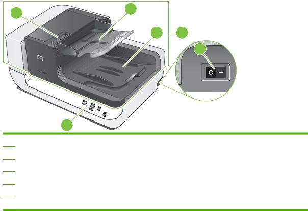
Product walkaround
Front and right-side view
Figure 1-1 Front and right-side view
5 |
3 |
|
4 2
6
1
1Front panel
2ADF
3ADF input tray
4ADF output tray
5Latch for opening the ADF jam door 1
6Power switch
4 Chapter 1 Product basics |
ENWW |
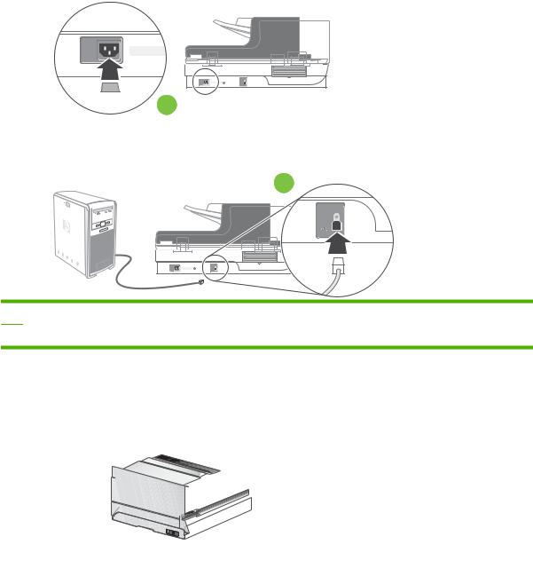
Back view
Figure 1-2 Back view
 1
1
2
1Power receptacle
2USB port
Side view (left)
Figure 1-3 Side view (left)
1
1 Scanner carriage lock
ENWW |
Product basics 5 |
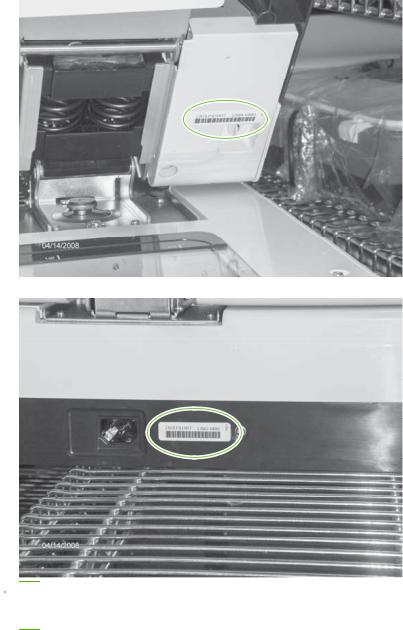
Model and serial numbers
The model and serial numbers are listed on identification labels located on the ADF and flatbed scanner.
Figure 1-4 Model and serial number (1 of 2)
Figure 1-5 Model and serial number (2 of 2)
 NOTE: If the product is owned by the U.S. government, the ADF and flatbed scanner have a special serial-number designation. Replacement components for these products must have a similar serialnumber designation.
6 Chapter 1 Product basics |
ENWW |
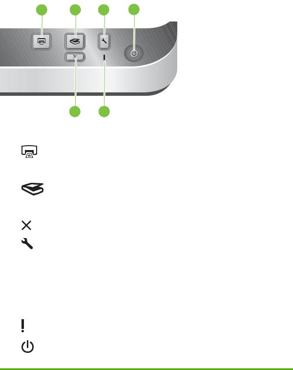
Control-panel walkaround
Figure 1-6 Control-panel features
1 |
2 |
4 |
6 |
|
|
|
|
|
|
|
|
3 |
5 |
|
Table 1-3 Control-panel features |
|
|
|
|
|
Item Icon |
Button name |
Description |
|
|
|
1 |
Copy |
By default, print the number of copies currently configured in |
|
|
HP Document Copy. |
|
|
Alternatively, start the scanning software that is assigned to this |
|
|
button. |
|
|
|
2 |
Scan |
By default, start a scan that uses the HP Smart Document Scan |
|
|
software profile that is assigned to this button. |
|
|
Alternatively, start the scanning software that is assigned to this |
|
|
button. |
|
|
|
3 |
Cancel |
Cancel a scan or copy in progress. |
|
|
|
4 |
Tools |
Open the HP Scanner Tools Utility where you can do the following |
|
|
tasks: |
|
|
● Associate the scanner control-panel buttons with scanning |
|
|
software. |
|
|
● Configure the buttons on the scanner front panel. |
|
|
● Manage the imprinter. |
|
|
● View information about scanner settings, status, and |
|
|
maintenance. |
|
|
|
5 |
Attention LED |
The Attention LED provides status information about the scanner. |
|
|
|
6 |
Power Save |
Press the Power Save button to put the scanner in Power Save |
|
|
mode when you are not using the scanner. When you are ready |
to begin scanning again, press the Power Save button to wake up the scanner.
ENWW |
Product basics 7 |
Supported product software
Supported operating systems
The product supports the following operating systems:
●Microsoft® Windows 2000
●Windows® XP Home/Professional
●Windows Vista®
●Linux 2.4 and 2.6 Kernel Available
Supported scanner drivers
The product supports the following scanner drivers:
●Twain
●ISIS
●WIA
Supported scanner-management software
HP Scanning Software CD
●HP Scanner Tools Utility
●HP Smart Document Scan
●Kofax VRS Pro
●Third-party document-management software
8 Chapter 1 Product basics |
ENWW |
Loading...