


 Loading...
User Service Guide
HP 9000 rp4410 and HP 9000 rp4440
Manufacturing Part Number: A9950-96011-ed4
Fourth Edition
September 2008
© Copyright 2003-2008 Hewlett-Packard Development Company, L.P.

Legal Notices
Copyright Notices. © Copyright 2003-2008 Hewlett-Packard Development Company, L.P.
The information contained herein is subject to change without notice. The only warranties for HP products and services are set forth in the express warranty statements accompanying such products and services. Nothing herein should be construed as constituting an additional warranty. HP shall not be liable for technical or editorial errors or omissions contained herein.
Printed in U.S.A.
Intel, Pentium, Intel Inside, Itanium, and the Intel Inside logo are trademarks or registered trademarks of Intel Corporation or its subsidiaries in the United States and other countries.
Linux is a U.S. registered trademark of Linus Torvalds.
2

Contents
1. Overview
HP 9000 rp4410 and rp4440 Server Views. . . . . . . . . . . . . . . . . . . . . . . . . . . . . . . . . . . . . . . . . . . . . . . . 20
Detailed Server Description . . . . . . . . . . . . . . . . . . . . . . . . . . . . . . . . . . . . . . . . . . . . . . . . . . . . . . . . . . . 21
I/O Subsystem . . . . . . . . . . . . . . . . . . . . . . . . . . . . . . . . . . . . . . . . . . . . . . . . . . . . . . . . . . . . . . . . . . . . . 21
Processors . . . . . . . . . . . . . . . . . . . . . . . . . . . . . . . . . . . . . . . . . . . . . . . . . . . . . . . . . . . . . . . . . . . . . . . . 22
Memory . . . . . . . . . . . . . . . . . . . . . . . . . . . . . . . . . . . . . . . . . . . . . . . . . . . . . . . . . . . . . . . . . . . . . . . . . . 22
Cooling. . . . . . . . . . . . . . . . . . . . . . . . . . . . . . . . . . . . . . . . . . . . . . . . . . . . . . . . . . . . . . . . . . . . . . . . . . . 23
Power Supply Unit . . . . . . . . . . . . . . . . . . . . . . . . . . . . . . . . . . . . . . . . . . . . . . . . . . . . . . . . . . . . . . . . . 23
Front Display Panel, DVD, and Diagnostic Panel. . . . . . . . . . . . . . . . . . . . . . . . . . . . . . . . . . . . . . . . . 23
Mass Storage. . . . . . . . . . . . . . . . . . . . . . . . . . . . . . . . . . . . . . . . . . . . . . . . . . . . . . . . . . . . . . . . . . . . . . 23
Firmware . . . . . . . . . . . . . . . . . . . . . . . . . . . . . . . . . . . . . . . . . . . . . . . . . . . . . . . . . . . . . . . . . . . . . . . . . 23
Dimensions and Values . . . . . . . . . . . . . . . . . . . . . . . . . . . . . . . . . . . . . . . . . . . . . . . . . . . . . . . . . . . . . . . 24
Controls, Ports, and LEDs . . . . . . . . . . . . . . . . . . . . . . . . . . . . . . . . . . . . . . . . . . . . . . . . . . . . . . . . . . . . . 24
Front Panel . . . . . . . . . . . . . . . . . . . . . . . . . . . . . . . . . . . . . . . . . . . . . . . . . . . . . . . . . . . . . . . . . . . . . . . 24
Rear Panel . . . . . . . . . . . . . . . . . . . . . . . . . . . . . . . . . . . . . . . . . . . . . . . . . . . . . . . . . . . . . . . . . . . . . . . . 28
USB Ports . . . . . . . . . . . . . . . . . . . . . . . . . . . . . . . . . . . . . . . . . . . . . . . . . . . . . . . . . . . . . . . . . . . . . . . . 34
VGA Port . . . . . . . . . . . . . . . . . . . . . . . . . . . . . . . . . . . . . . . . . . . . . . . . . . . . . . . . . . . . . . . . . . . . . . . . . 34
Serial Ports . . . . . . . . . . . . . . . . . . . . . . . . . . . . . . . . . . . . . . . . . . . . . . . . . . . . . . . . . . . . . . . . . . . . . . . 34
iLO MP LAN Port . . . . . . . . . . . . . . . . . . . . . . . . . . . . . . . . . . . . . . . . . . . . . . . . . . . . . . . . . . . . . . . . . . 35
Gigabit Ethernet LAN Port . . . . . . . . . . . . . . . . . . . . . . . . . . . . . . . . . . . . . . . . . . . . . . . . . . . . . . . . . . 36
SCSI Port, Ultra 3, 68-Pin . . . . . . . . . . . . . . . . . . . . . . . . . . . . . . . . . . . . . . . . . . . . . . . . . . . . . . . . . . . 36
Additional Controls and LEDs. . . . . . . . . . . . . . . . . . . . . . . . . . . . . . . . . . . . . . . . . . . . . . . . . . . . . . . . 39
Powering the Server On and Off . . . . . . . . . . . . . . . . . . . . . . . . . . . . . . . . . . . . . . . . . . . . . . . . . . . . . . . . 42
Power States . . . . . . . . . . . . . . . . . . . . . . . . . . . . . . . . . . . . . . . . . . . . . . . . . . . . . . . . . . . . . . . . . . . . . . 42
Powering On the Server . . . . . . . . . . . . . . . . . . . . . . . . . . . . . . . . . . . . . . . . . . . . . . . . . . . . . . . . . . . . . 43
Powering Off the Server . . . . . . . . . . . . . . . . . . . . . . . . . . . . . . . . . . . . . . . . . . . . . . . . . . . . . . . . . . . . . 44
2. System Specifications
System Configuration . . . . . . . . . . . . . . . . . . . . . . . . . . . . . . . . . . . . . . . . . . . . . . . . . . . . . . . . . . . . . . . . 45
Dimensions and Values . . . . . . . . . . . . . . . . . . . . . . . . . . . . . . . . . . . . . . . . . . . . . . . . . . . . . . . . . . . . . . . 46
Grounding. . . . . . . . . . . . . . . . . . . . . . . . . . . . . . . . . . . . . . . . . . . . . . . . . . . . . . . . . . . . . . . . . . . . . . . . . . 46
Electrical Specifications. . . . . . . . . . . . . . . . . . . . . . . . . . . . . . . . . . . . . . . . . . . . . . . . . . . . . . . . . . . . . . . 47
AC Power Cords . . . . . . . . . . . . . . . . . . . . . . . . . . . . . . . . . . . . . . . . . . . . . . . . . . . . . . . . . . . . . . . . . . . 47
Circuit Breaker . . . . . . . . . . . . . . . . . . . . . . . . . . . . . . . . . . . . . . . . . . . . . . . . . . . . . . . . . . . . . . . . . . . . 47
System Power Specifications . . . . . . . . . . . . . . . . . . . . . . . . . . . . . . . . . . . . . . . . . . . . . . . . . . . . . . . . . 47
Power and Cooling . . . . . . . . . . . . . . . . . . . . . . . . . . . . . . . . . . . . . . . . . . . . . . . . . . . . . . . . . . . . . . . . . 49
Environmental Specifications . . . . . . . . . . . . . . . . . . . . . . . . . . . . . . . . . . . . . . . . . . . . . . . . . . . . . . . . . . 50
Operating Environment . . . . . . . . . . . . . . . . . . . . . . . . . . . . . . . . . . . . . . . . . . . . . . . . . . . . . . . . . . . . . 50
Environmental Temperature Sensor . . . . . . . . . . . . . . . . . . . . . . . . . . . . . . . . . . . . . . . . . . . . . . . . . . . 50
Nonoperating Environment . . . . . . . . . . . . . . . . . . . . . . . . . . . . . . . . . . . . . . . . . . . . . . . . . . . . . . . . . . 50
Cooling. . . . . . . . . . . . . . . . . . . . . . . . . . . . . . . . . . . . . . . . . . . . . . . . . . . . . . . . . . . . . . . . . . . . . . . . . . . 51
Acoustic Noise Specification. . . . . . . . . . . . . . . . . . . . . . . . . . . . . . . . . . . . . . . . . . . . . . . . . . . . . . . . . . 52
Physical and Environmental Specifications . . . . . . . . . . . . . . . . . . . . . . . . . . . . . . . . . . . . . . . . . . . . . . . 53
3. Installing the System
Introduction . . . . . . . . . . . . . . . . . . . . . . . . . . . . . . . . . . . . . . . . . . . . . . . . . . . . . . . . . . . . . . . . . . . . . . . . 55
3

Contents
Server Views. . . . . . . . . . . . . . . . . . . . . . . . . . . . . . . . . . . . . . . . . . . . . . . . . . . . . . . . . . . . . . . . . . . . . . . . 56 Detailed Server Description . . . . . . . . . . . . . . . . . . . . . . . . . . . . . . . . . . . . . . . . . . . . . . . . . . . . . . . . . . . 57 I/O Subsystem . . . . . . . . . . . . . . . . . . . . . . . . . . . . . . . . . . . . . . . . . . . . . . . . . . . . . . . . . . . . . . . . . . . . . 57 Processors . . . . . . . . . . . . . . . . . . . . . . . . . . . . . . . . . . . . . . . . . . . . . . . . . . . . . . . . . . . . . . . . . . . . . . . . 58 Memory . . . . . . . . . . . . . . . . . . . . . . . . . . . . . . . . . . . . . . . . . . . . . . . . . . . . . . . . . . . . . . . . . . . . . . . . . . 58 Cooling. . . . . . . . . . . . . . . . . . . . . . . . . . . . . . . . . . . . . . . . . . . . . . . . . . . . . . . . . . . . . . . . . . . . . . . . . . . 59 Power Supply Unit . . . . . . . . . . . . . . . . . . . . . . . . . . . . . . . . . . . . . . . . . . . . . . . . . . . . . . . . . . . . . . . . . 59 Front Display Panel, DVD, and Diagnostic Panel. . . . . . . . . . . . . . . . . . . . . . . . . . . . . . . . . . . . . . . . . 59 Mass Storage. . . . . . . . . . . . . . . . . . . . . . . . . . . . . . . . . . . . . . . . . . . . . . . . . . . . . . . . . . . . . . . . . . . . . . 59 Firmware . . . . . . . . . . . . . . . . . . . . . . . . . . . . . . . . . . . . . . . . . . . . . . . . . . . . . . . . . . . . . . . . . . . . . . . . . 59 Dimensions and Values . . . . . . . . . . . . . . . . . . . . . . . . . . . . . . . . . . . . . . . . . . . . . . . . . . . . . . . . . . . . . 60 Safety Information . . . . . . . . . . . . . . . . . . . . . . . . . . . . . . . . . . . . . . . . . . . . . . . . . . . . . . . . . . . . . . . . . . . 60 Installation Sequence and Checklist. . . . . . . . . . . . . . . . . . . . . . . . . . . . . . . . . . . . . . . . . . . . . . . . . . . . . 61 Unpacking and Inspecting the Server . . . . . . . . . . . . . . . . . . . . . . . . . . . . . . . . . . . . . . . . . . . . . . . . . . . 62 Verifying Site Preparation . . . . . . . . . . . . . . . . . . . . . . . . . . . . . . . . . . . . . . . . . . . . . . . . . . . . . . . . . . . 62 Inspecting the Shipping Containers for Damage . . . . . . . . . . . . . . . . . . . . . . . . . . . . . . . . . . . . . . . . . 62 Unpacking the Server. . . . . . . . . . . . . . . . . . . . . . . . . . . . . . . . . . . . . . . . . . . . . . . . . . . . . . . . . . . . . . . 62 Checking the Inventory . . . . . . . . . . . . . . . . . . . . . . . . . . . . . . . . . . . . . . . . . . . . . . . . . . . . . . . . . . . . . 62 Returning Damaged Equipment . . . . . . . . . . . . . . . . . . . . . . . . . . . . . . . . . . . . . . . . . . . . . . . . . . . . . . 63 Unloading the Server with a Lifter . . . . . . . . . . . . . . . . . . . . . . . . . . . . . . . . . . . . . . . . . . . . . . . . . . . . 63 Installing Additional Components . . . . . . . . . . . . . . . . . . . . . . . . . . . . . . . . . . . . . . . . . . . . . . . . . . . . . . 63 Service Tools Required . . . . . . . . . . . . . . . . . . . . . . . . . . . . . . . . . . . . . . . . . . . . . . . . . . . . . . . . . . . . . . 63 Accessing a Rack-Mounted Server. . . . . . . . . . . . . . . . . . . . . . . . . . . . . . . . . . . . . . . . . . . . . . . . . . . . . 64 Accessing a Pedestal-Mounted Server . . . . . . . . . . . . . . . . . . . . . . . . . . . . . . . . . . . . . . . . . . . . . . . . . . 65 Front Panel Controls and Indicators . . . . . . . . . . . . . . . . . . . . . . . . . . . . . . . . . . . . . . . . . . . . . . . . . . . 66 Additional Controls and Indicators . . . . . . . . . . . . . . . . . . . . . . . . . . . . . . . . . . . . . . . . . . . . . . . . . . . . 70 Front Bezel . . . . . . . . . . . . . . . . . . . . . . . . . . . . . . . . . . . . . . . . . . . . . . . . . . . . . . . . . . . . . . . . . . . . . . . 71 Front and Top Covers . . . . . . . . . . . . . . . . . . . . . . . . . . . . . . . . . . . . . . . . . . . . . . . . . . . . . . . . . . . . . . . 72 Hot-Swappable Chassis Fan Units . . . . . . . . . . . . . . . . . . . . . . . . . . . . . . . . . . . . . . . . . . . . . . . . . . . . 75 I/O Baseboard Assembly. . . . . . . . . . . . . . . . . . . . . . . . . . . . . . . . . . . . . . . . . . . . . . . . . . . . . . . . . . . . . 77 System Battery . . . . . . . . . . . . . . . . . . . . . . . . . . . . . . . . . . . . . . . . . . . . . . . . . . . . . . . . . . . . . . . . . . . . 81 Installing Power Supplies and Disk Drives. . . . . . . . . . . . . . . . . . . . . . . . . . . . . . . . . . . . . . . . . . . . . . 83 Installing Processors. . . . . . . . . . . . . . . . . . . . . . . . . . . . . . . . . . . . . . . . . . . . . . . . . . . . . . . . . . . . . . . . 86 Installing Memory . . . . . . . . . . . . . . . . . . . . . . . . . . . . . . . . . . . . . . . . . . . . . . . . . . . . . . . . . . . . . . . . . 94 Hot-Pluggable PCI/PCI-X. . . . . . . . . . . . . . . . . . . . . . . . . . . . . . . . . . . . . . . . . . . . . . . . . . . . . . . . . . . 100 Converting SCSI From Simplex to Duplex . . . . . . . . . . . . . . . . . . . . . . . . . . . . . . . . . . . . . . . . . . . . . 109 Installing the Server Into a Rack, Non-HP rack, or Pedestal . . . . . . . . . . . . . . . . . . . . . . . . . . . . . . . . 115 HP Rack. . . . . . . . . . . . . . . . . . . . . . . . . . . . . . . . . . . . . . . . . . . . . . . . . . . . . . . . . . . . . . . . . . . . . . . . . 115 Non-HP Rack. . . . . . . . . . . . . . . . . . . . . . . . . . . . . . . . . . . . . . . . . . . . . . . . . . . . . . . . . . . . . . . . . . . . . 115 Pedestal Mount . . . . . . . . . . . . . . . . . . . . . . . . . . . . . . . . . . . . . . . . . . . . . . . . . . . . . . . . . . . . . . . . . . . 115 Connecting the Cables . . . . . . . . . . . . . . . . . . . . . . . . . . . . . . . . . . . . . . . . . . . . . . . . . . . . . . . . . . . . . . . 116 AC Input Power. . . . . . . . . . . . . . . . . . . . . . . . . . . . . . . . . . . . . . . . . . . . . . . . . . . . . . . . . . . . . . . . . . . 116 Core I/O Connections . . . . . . . . . . . . . . . . . . . . . . . . . . . . . . . . . . . . . . . . . . . . . . . . . . . . . . . . . . . . . . 116 Applying Standby Power to the Server . . . . . . . . . . . . . . . . . . . . . . . . . . . . . . . . . . . . . . . . . . . . . . . . 117 Connecting to the LAN . . . . . . . . . . . . . . . . . . . . . . . . . . . . . . . . . . . . . . . . . . . . . . . . . . . . . . . . . . . . . 117 Console Setup. . . . . . . . . . . . . . . . . . . . . . . . . . . . . . . . . . . . . . . . . . . . . . . . . . . . . . . . . . . . . . . . . . . . . . 118
4

Contents
Setting Up the Console. . . . . . . . . . . . . . . . . . . . . . . . . . . . . . . . . . . . . . . . . . . . . . . . . . . . . . . . . . . . . 118 Setup Checklist . . . . . . . . . . . . . . . . . . . . . . . . . . . . . . . . . . . . . . . . . . . . . . . . . . . . . . . . . . . . . . . . . . . 119 Setup Flowchart . . . . . . . . . . . . . . . . . . . . . . . . . . . . . . . . . . . . . . . . . . . . . . . . . . . . . . . . . . . . . . . . . . 120 Preparation . . . . . . . . . . . . . . . . . . . . . . . . . . . . . . . . . . . . . . . . . . . . . . . . . . . . . . . . . . . . . . . . . . . . . . 121 Configuring the iLO MP LAN Using DHCP and DNS . . . . . . . . . . . . . . . . . . . . . . . . . . . . . . . . . . . . 122 Configuring the iLO MP LAN Using ARP Ping . . . . . . . . . . . . . . . . . . . . . . . . . . . . . . . . . . . . . . . . . 122 Configuring the iLO MP LAN Using the RS-232 Serial Port. . . . . . . . . . . . . . . . . . . . . . . . . . . . . . . 124 Logging In to the iLO MP. . . . . . . . . . . . . . . . . . . . . . . . . . . . . . . . . . . . . . . . . . . . . . . . . . . . . . . . . . . 125 Additional Setup . . . . . . . . . . . . . . . . . . . . . . . . . . . . . . . . . . . . . . . . . . . . . . . . . . . . . . . . . . . . . . . . . . 126
Accessing the Host Console . . . . . . . . . . . . . . . . . . . . . . . . . . . . . . . . . . . . . . . . . . . . . . . . . . . . . . . . . . . 127 Accessing the Host Console With the TUI - CO Command . . . . . . . . . . . . . . . . . . . . . . . . . . . . . . . . 127 Interacting with the iLO MP Using the Web GUI . . . . . . . . . . . . . . . . . . . . . . . . . . . . . . . . . . . . . . . 127 Accessing the Graphic Console Using VGA. . . . . . . . . . . . . . . . . . . . . . . . . . . . . . . . . . . . . . . . . . . . . 129 Powering the Server ON and Off. . . . . . . . . . . . . . . . . . . . . . . . . . . . . . . . . . . . . . . . . . . . . . . . . . . . . . . 131 Power States . . . . . . . . . . . . . . . . . . . . . . . . . . . . . . . . . . . . . . . . . . . . . . . . . . . . . . . . . . . . . . . . . . . . . 131 Powering On the Server . . . . . . . . . . . . . . . . . . . . . . . . . . . . . . . . . . . . . . . . . . . . . . . . . . . . . . . . . . . . 131 Powering Off the Server . . . . . . . . . . . . . . . . . . . . . . . . . . . . . . . . . . . . . . . . . . . . . . . . . . . . . . . . . . . . 132 Booting the Operating System . . . . . . . . . . . . . . . . . . . . . . . . . . . . . . . . . . . . . . . . . . . . . . . . . . . . . . . . 134 Supported Operating System. . . . . . . . . . . . . . . . . . . . . . . . . . . . . . . . . . . . . . . . . . . . . . . . . . . . . . . . 134 Booting and Shutting Down HP-UX . . . . . . . . . . . . . . . . . . . . . . . . . . . . . . . . . . . . . . . . . . . . . . . . . . 134 Verifying the Server Configuration Using Boot Console Handler . . . . . . . . . . . . . . . . . . . . . . . . . . . 135 Troubleshooting . . . . . . . . . . . . . . . . . . . . . . . . . . . . . . . . . . . . . . . . . . . . . . . . . . . . . . . . . . . . . . . . . . . . 136 Troubleshooting Methodology . . . . . . . . . . . . . . . . . . . . . . . . . . . . . . . . . . . . . . . . . . . . . . . . . . . . . . . 136 Troubleshooting Using the Server Power Button . . . . . . . . . . . . . . . . . . . . . . . . . . . . . . . . . . . . . . . . 136 Server Does Not Power On. . . . . . . . . . . . . . . . . . . . . . . . . . . . . . . . . . . . . . . . . . . . . . . . . . . . . . . . . . 137 BCH Menu is Not Available . . . . . . . . . . . . . . . . . . . . . . . . . . . . . . . . . . . . . . . . . . . . . . . . . . . . . . . . . 138 Operating System Does Not Boot . . . . . . . . . . . . . . . . . . . . . . . . . . . . . . . . . . . . . . . . . . . . . . . . . . . . 138 Operating System Boots with Problems . . . . . . . . . . . . . . . . . . . . . . . . . . . . . . . . . . . . . . . . . . . . . . . 138 Intermittent Server Problems . . . . . . . . . . . . . . . . . . . . . . . . . . . . . . . . . . . . . . . . . . . . . . . . . . . . . . . 138 DVD Problems. . . . . . . . . . . . . . . . . . . . . . . . . . . . . . . . . . . . . . . . . . . . . . . . . . . . . . . . . . . . . . . . . . . . 139 Hard Drive Problems . . . . . . . . . . . . . . . . . . . . . . . . . . . . . . . . . . . . . . . . . . . . . . . . . . . . . . . . . . . . . . 139 Console Problems . . . . . . . . . . . . . . . . . . . . . . . . . . . . . . . . . . . . . . . . . . . . . . . . . . . . . . . . . . . . . . . . . 139 Downloading and Installing the Latest Version of the Firmware . . . . . . . . . . . . . . . . . . . . . . . . . . . 139 Troubleshooting Using LED Indicators. . . . . . . . . . . . . . . . . . . . . . . . . . . . . . . . . . . . . . . . . . . . . . . . 140 Information to Collect Before You Contact Support . . . . . . . . . . . . . . . . . . . . . . . . . . . . . . . . . . . . . . 144
4. Booting the Operating System
Supported Operating System . . . . . . . . . . . . . . . . . . . . . . . . . . . . . . . . . . . . . . . . . . . . . . . . . . . . . . . . . 145 Booting and Shutting Down HP-UX . . . . . . . . . . . . . . . . . . . . . . . . . . . . . . . . . . . . . . . . . . . . . . . . . . . . 146 Standard HP-UX Booting Using Boot Console Handler. . . . . . . . . . . . . . . . . . . . . . . . . . . . . . . . . . . 146 Booting HP-UX in Single-User Mode . . . . . . . . . . . . . . . . . . . . . . . . . . . . . . . . . . . . . . . . . . . . . . . . . 147 Booting HP-UX in LVM Maintenance Mode . . . . . . . . . . . . . . . . . . . . . . . . . . . . . . . . . . . . . . . . . . . . 147 Shutting Down HP-UX . . . . . . . . . . . . . . . . . . . . . . . . . . . . . . . . . . . . . . . . . . . . . . . . . . . . . . . . . . . . . 147 Verifying the Server Configuration Using Boot Console Handler. . . . . . . . . . . . . . . . . . . . . . . . . . . . . 148
5. Troubleshooting
5

Contents
Troubleshooting Methodology . . . . . . . . . . . . . . . . . . . . . . . . . . . . . . . . . . . . . . . . . . . . . . . . . . . . . . . . . 149 Troubleshooting System Power . . . . . . . . . . . . . . . . . . . . . . . . . . . . . . . . . . . . . . . . . . . . . . . . . . . . . . . . 150 Using the Front Panel Power Button. . . . . . . . . . . . . . . . . . . . . . . . . . . . . . . . . . . . . . . . . . . . . . . . . . 150 System Does Not Successfully Power On and Remain Powered On . . . . . . . . . . . . . . . . . . . . . . . . . 150 Operating System Boots. . . . . . . . . . . . . . . . . . . . . . . . . . . . . . . . . . . . . . . . . . . . . . . . . . . . . . . . . . . . 155 Operating System Does Not Boot . . . . . . . . . . . . . . . . . . . . . . . . . . . . . . . . . . . . . . . . . . . . . . . . . . . . 155 Troubleshooting Using Online Support Tools . . . . . . . . . . . . . . . . . . . . . . . . . . . . . . . . . . . . . . . . . . . . 155 Support Tools Manager . . . . . . . . . . . . . . . . . . . . . . . . . . . . . . . . . . . . . . . . . . . . . . . . . . . . . . . . . . . . 155 Event Monitoring Service. . . . . . . . . . . . . . . . . . . . . . . . . . . . . . . . . . . . . . . . . . . . . . . . . . . . . . . . . . . 156 iLO MP . . . . . . . . . . . . . . . . . . . . . . . . . . . . . . . . . . . . . . . . . . . . . . . . . . . . . . . . . . . . . . . . . . . . . . . . . 156 Troubleshooting Using Offline Support Tools . . . . . . . . . . . . . . . . . . . . . . . . . . . . . . . . . . . . . . . . . . . . 158 ODE . . . . . . . . . . . . . . . . . . . . . . . . . . . . . . . . . . . . . . . . . . . . . . . . . . . . . . . . . . . . . . . . . . . . . . . . . . . . 158 Troubleshooting PCI/PCI-X Hot-Pluggable Operations . . . . . . . . . . . . . . . . . . . . . . . . . . . . . . . . . . . 160 Troubleshooting Using LED Indicators . . . . . . . . . . . . . . . . . . . . . . . . . . . . . . . . . . . . . . . . . . . . . . . . . 161 Front Control Panel LEDs . . . . . . . . . . . . . . . . . . . . . . . . . . . . . . . . . . . . . . . . . . . . . . . . . . . . . . . . . . 161 QuickFind Diagnostic Panel LEDs . . . . . . . . . . . . . . . . . . . . . . . . . . . . . . . . . . . . . . . . . . . . . . . . . . . 163 I/O Baseboard LED Indicators. . . . . . . . . . . . . . . . . . . . . . . . . . . . . . . . . . . . . . . . . . . . . . . . . . . . . . . 165 Memory Extender Boards. . . . . . . . . . . . . . . . . . . . . . . . . . . . . . . . . . . . . . . . . . . . . . . . . . . . . . . . . . . 166 Disk and I/O Path Logging . . . . . . . . . . . . . . . . . . . . . . . . . . . . . . . . . . . . . . . . . . . . . . . . . . . . . . . . . . . 169 Core I/O Connections . . . . . . . . . . . . . . . . . . . . . . . . . . . . . . . . . . . . . . . . . . . . . . . . . . . . . . . . . . . . . . . . 171 System I/O Board Switches and Jumpers. . . . . . . . . . . . . . . . . . . . . . . . . . . . . . . . . . . . . . . . . . . . . . . . 172
6. Removing and Replacing Components
Safety Information . . . . . . . . . . . . . . . . . . . . . . . . . . . . . . . . . . . . . . . . . . . . . . . . . . . . . . . . . . . . . . . . . . 176
Required Service Tools. . . . . . . . . . . . . . . . . . . . . . . . . . . . . . . . . . . . . . . . . . . . . . . . . . . . . . . . . . . . . . . 176
Accessing a Rack-Mounted Server . . . . . . . . . . . . . . . . . . . . . . . . . . . . . . . . . . . . . . . . . . . . . . . . . . . . . 177
Extend the Server from the Rack. . . . . . . . . . . . . . . . . . . . . . . . . . . . . . . . . . . . . . . . . . . . . . . . . . . . . 177
Inserting the Server Into the Rack . . . . . . . . . . . . . . . . . . . . . . . . . . . . . . . . . . . . . . . . . . . . . . . . . . . 178
Accessing a Pedestal-Mounted Server . . . . . . . . . . . . . . . . . . . . . . . . . . . . . . . . . . . . . . . . . . . . . . . . . . 178
Front Bezel . . . . . . . . . . . . . . . . . . . . . . . . . . . . . . . . . . . . . . . . . . . . . . . . . . . . . . . . . . . . . . . . . . . . . . . . 180
Removing the Front Bezel . . . . . . . . . . . . . . . . . . . . . . . . . . . . . . . . . . . . . . . . . . . . . . . . . . . . . . . . . . 180
Replacing the Front Bezel . . . . . . . . . . . . . . . . . . . . . . . . . . . . . . . . . . . . . . . . . . . . . . . . . . . . . . . . . . 180
Front and Top Covers . . . . . . . . . . . . . . . . . . . . . . . . . . . . . . . . . . . . . . . . . . . . . . . . . . . . . . . . . . . . . . . 181
Removing the Front Cover . . . . . . . . . . . . . . . . . . . . . . . . . . . . . . . . . . . . . . . . . . . . . . . . . . . . . . . . . . 181
Replacing the Front Cover . . . . . . . . . . . . . . . . . . . . . . . . . . . . . . . . . . . . . . . . . . . . . . . . . . . . . . . . . . 182
Removing the Top Cover. . . . . . . . . . . . . . . . . . . . . . . . . . . . . . . . . . . . . . . . . . . . . . . . . . . . . . . . . . . . 182
Replacing the Top Cover. . . . . . . . . . . . . . . . . . . . . . . . . . . . . . . . . . . . . . . . . . . . . . . . . . . . . . . . . . . . 183
Memory Extender Board . . . . . . . . . . . . . . . . . . . . . . . . . . . . . . . . . . . . . . . . . . . . . . . . . . . . . . . . . . . . . 184
Removing a Memory Extender Board . . . . . . . . . . . . . . . . . . . . . . . . . . . . . . . . . . . . . . . . . . . . . . . . . 184
Replacing the Memory Extender Board . . . . . . . . . . . . . . . . . . . . . . . . . . . . . . . . . . . . . . . . . . . . . . . 186
System Memory DIMMs . . . . . . . . . . . . . . . . . . . . . . . . . . . . . . . . . . . . . . . . . . . . . . . . . . . . . . . . . . . . . 187
Replacing Deallocated Memory Ranks . . . . . . . . . . . . . . . . . . . . . . . . . . . . . . . . . . . . . . . . . . . . . . . . 187
Removing Memory DIMMs . . . . . . . . . . . . . . . . . . . . . . . . . . . . . . . . . . . . . . . . . . . . . . . . . . . . . . . . . 187
Installing Memory DIMMs. . . . . . . . . . . . . . . . . . . . . . . . . . . . . . . . . . . . . . . . . . . . . . . . . . . . . . . . . . 188
Processor Extender Board . . . . . . . . . . . . . . . . . . . . . . . . . . . . . . . . . . . . . . . . . . . . . . . . . . . . . . . . . . . . 192
Removing the Processor Extender Board . . . . . . . . . . . . . . . . . . . . . . . . . . . . . . . . . . . . . . . . . . . . . . 192
6

Contents
Replacing the Processor Extender Board . . . . . . . . . . . . . . . . . . . . . . . . . . . . . . . . . . . . . . . . . . . . . . 194 Replacing Dual Processor Modules . . . . . . . . . . . . . . . . . . . . . . . . . . . . . . . . . . . . . . . . . . . . . . . . . . . . . 196 Dual Processor Modules . . . . . . . . . . . . . . . . . . . . . . . . . . . . . . . . . . . . . . . . . . . . . . . . . . . . . . . . . . . . 196 Processor Load Order . . . . . . . . . . . . . . . . . . . . . . . . . . . . . . . . . . . . . . . . . . . . . . . . . . . . . . . . . . . . . . 196 Removing a Dual Processor Module . . . . . . . . . . . . . . . . . . . . . . . . . . . . . . . . . . . . . . . . . . . . . . . . . . 197 Installing a Dual Processor Module. . . . . . . . . . . . . . . . . . . . . . . . . . . . . . . . . . . . . . . . . . . . . . . . . . . 199 Hot-Swappable Chassis Fan Unit . . . . . . . . . . . . . . . . . . . . . . . . . . . . . . . . . . . . . . . . . . . . . . . . . . . . . . 203 Removing a Hot-Swappable Chassis Fan Unit . . . . . . . . . . . . . . . . . . . . . . . . . . . . . . . . . . . . . . . . . . 203 Replacing a Hot-Swappable Chassis Fan Unit . . . . . . . . . . . . . . . . . . . . . . . . . . . . . . . . . . . . . . . . . . 206 I/O Baseboard Assembly . . . . . . . . . . . . . . . . . . . . . . . . . . . . . . . . . . . . . . . . . . . . . . . . . . . . . . . . . . . . . 206 Removing the I/O Baseboard Assembly. . . . . . . . . . . . . . . . . . . . . . . . . . . . . . . . . . . . . . . . . . . . . . . . 207 Replacing the I/O Baseboard Assembly. . . . . . . . . . . . . . . . . . . . . . . . . . . . . . . . . . . . . . . . . . . . . . . . 209 Removing and Replacing the I/O Baseboard Locking Lever . . . . . . . . . . . . . . . . . . . . . . . . . . . . . . . 213 System Battery. . . . . . . . . . . . . . . . . . . . . . . . . . . . . . . . . . . . . . . . . . . . . . . . . . . . . . . . . . . . . . . . . . . . . 213 Battery Notice . . . . . . . . . . . . . . . . . . . . . . . . . . . . . . . . . . . . . . . . . . . . . . . . . . . . . . . . . . . . . . . . . . . . 213 Replacing the System Battery . . . . . . . . . . . . . . . . . . . . . . . . . . . . . . . . . . . . . . . . . . . . . . . . . . . . . . . 214 Removing and Replacing PCI/PCI-X Cards . . . . . . . . . . . . . . . . . . . . . . . . . . . . . . . . . . . . . . . . . . . . . . 216 PCI/PCI-X Configurations . . . . . . . . . . . . . . . . . . . . . . . . . . . . . . . . . . . . . . . . . . . . . . . . . . . . . . . . . . 217 OLA . . . . . . . . . . . . . . . . . . . . . . . . . . . . . . . . . . . . . . . . . . . . . . . . . . . . . . . . . . . . . . . . . . . . . . . . . . . . 220 OLR . . . . . . . . . . . . . . . . . . . . . . . . . . . . . . . . . . . . . . . . . . . . . . . . . . . . . . . . . . . . . . . . . . . . . . . . . . . . 225 Removing a PCI/PCI-X Card Offline . . . . . . . . . . . . . . . . . . . . . . . . . . . . . . . . . . . . . . . . . . . . . . . . . . 226 Installing a PCI Card Offline . . . . . . . . . . . . . . . . . . . . . . . . . . . . . . . . . . . . . . . . . . . . . . . . . . . . . . . . 227 OLX Dividers . . . . . . . . . . . . . . . . . . . . . . . . . . . . . . . . . . . . . . . . . . . . . . . . . . . . . . . . . . . . . . . . . . . . . . 228 Removing an OLX Divider . . . . . . . . . . . . . . . . . . . . . . . . . . . . . . . . . . . . . . . . . . . . . . . . . . . . . . . . . . 228 Replacing an OLX Divider . . . . . . . . . . . . . . . . . . . . . . . . . . . . . . . . . . . . . . . . . . . . . . . . . . . . . . . . . . 231 U320 SCSI Enablement and Conversion Procedures . . . . . . . . . . . . . . . . . . . . . . . . . . . . . . . . . . . . . . 231 Time Required. . . . . . . . . . . . . . . . . . . . . . . . . . . . . . . . . . . . . . . . . . . . . . . . . . . . . . . . . . . . . . . . . . . . 231 Upgrade Tasks . . . . . . . . . . . . . . . . . . . . . . . . . . . . . . . . . . . . . . . . . . . . . . . . . . . . . . . . . . . . . . . . . . . 232 Back Up Your System . . . . . . . . . . . . . . . . . . . . . . . . . . . . . . . . . . . . . . . . . . . . . . . . . . . . . . . . . . . . . . 232 Removing Server Components . . . . . . . . . . . . . . . . . . . . . . . . . . . . . . . . . . . . . . . . . . . . . . . . . . . . . . . 232 Removing the SCSI Duplex Board. . . . . . . . . . . . . . . . . . . . . . . . . . . . . . . . . . . . . . . . . . . . . . . . . . . . 233 Removing the SCSI Backplane . . . . . . . . . . . . . . . . . . . . . . . . . . . . . . . . . . . . . . . . . . . . . . . . . . . . . . 235 Replacing the SCSI Backplane . . . . . . . . . . . . . . . . . . . . . . . . . . . . . . . . . . . . . . . . . . . . . . . . . . . . . . 237 Installing the SCSI Duplex Board . . . . . . . . . . . . . . . . . . . . . . . . . . . . . . . . . . . . . . . . . . . . . . . . . . . . 238 Installing the Server Components . . . . . . . . . . . . . . . . . . . . . . . . . . . . . . . . . . . . . . . . . . . . . . . . . . . . 239 Verify the Upgrade Installation . . . . . . . . . . . . . . . . . . . . . . . . . . . . . . . . . . . . . . . . . . . . . . . . . . . . . . 240 Converting SCSI From Duplex to Simplex Operation . . . . . . . . . . . . . . . . . . . . . . . . . . . . . . . . . . . . 240 Removing and Replacing Core I/O Cards . . . . . . . . . . . . . . . . . . . . . . . . . . . . . . . . . . . . . . . . . . . . . . . . 245 Safety Information . . . . . . . . . . . . . . . . . . . . . . . . . . . . . . . . . . . . . . . . . . . . . . . . . . . . . . . . . . . . . . . . 245 Required Service Tools . . . . . . . . . . . . . . . . . . . . . . . . . . . . . . . . . . . . . . . . . . . . . . . . . . . . . . . . . . . . . 245 PCI Slot Locations and Configurations . . . . . . . . . . . . . . . . . . . . . . . . . . . . . . . . . . . . . . . . . . . . . . . . 246 Removing the LAN Core I/O Card . . . . . . . . . . . . . . . . . . . . . . . . . . . . . . . . . . . . . . . . . . . . . . . . . . . . 246 Installing the LAN Core I/O Card . . . . . . . . . . . . . . . . . . . . . . . . . . . . . . . . . . . . . . . . . . . . . . . . . . . . 247 Removing the SCSI Core I/O Card . . . . . . . . . . . . . . . . . . . . . . . . . . . . . . . . . . . . . . . . . . . . . . . . . . . 247 Hot-Pluggable Disk Drives . . . . . . . . . . . . . . . . . . . . . . . . . . . . . . . . . . . . . . . . . . . . . . . . . . . . . . . . . . . 250 Removing a Hot-Pluggable Disk Drive . . . . . . . . . . . . . . . . . . . . . . . . . . . . . . . . . . . . . . . . . . . . . . . . 250
7

Contents
Replacing a Hot-Pluggable Disk Drive . . . . . . . . . . . . . . . . . . . . . . . . . . . . . . . . . . . . . . . . . . . . . . . . 250
SCSI Backplane . . . . . . . . . . . . . . . . . . . . . . . . . . . . . . . . . . . . . . . . . . . . . . . . . . . . . . . . . . . . . . . . . . . . 252
Removing the SCSI Backplane . . . . . . . . . . . . . . . . . . . . . . . . . . . . . . . . . . . . . . . . . . . . . . . . . . . . . . 253
Replacing the SCSI Backplane . . . . . . . . . . . . . . . . . . . . . . . . . . . . . . . . . . . . . . . . . . . . . . . . . . . . . . 254
Midplane Riser Board . . . . . . . . . . . . . . . . . . . . . . . . . . . . . . . . . . . . . . . . . . . . . . . . . . . . . . . . . . . . . . . 255
Removing the Midplane Riser Board. . . . . . . . . . . . . . . . . . . . . . . . . . . . . . . . . . . . . . . . . . . . . . . . . . 255
Replacing the Midplane Riser Board. . . . . . . . . . . . . . . . . . . . . . . . . . . . . . . . . . . . . . . . . . . . . . . . . . 258
Hot-Swappable Power Supplies. . . . . . . . . . . . . . . . . . . . . . . . . . . . . . . . . . . . . . . . . . . . . . . . . . . . . . . . 258
Power Supply Load Order . . . . . . . . . . . . . . . . . . . . . . . . . . . . . . . . . . . . . . . . . . . . . . . . . . . . . . . . . . 259
Removing a Hot-Swappable Power Supply . . . . . . . . . . . . . . . . . . . . . . . . . . . . . . . . . . . . . . . . . . . . . 259
Replacing a Hot-Swappable Power Supply . . . . . . . . . . . . . . . . . . . . . . . . . . . . . . . . . . . . . . . . . . . . . 260
Power Distribution Board . . . . . . . . . . . . . . . . . . . . . . . . . . . . . . . . . . . . . . . . . . . . . . . . . . . . . . . . . . . . 261
Removing the Power Distribution Board. . . . . . . . . . . . . . . . . . . . . . . . . . . . . . . . . . . . . . . . . . . . . . . 261
Replacing the Power Distribution Board. . . . . . . . . . . . . . . . . . . . . . . . . . . . . . . . . . . . . . . . . . . . . . . 262
DVD Drive . . . . . . . . . . . . . . . . . . . . . . . . . . . . . . . . . . . . . . . . . . . . . . . . . . . . . . . . . . . . . . . . . . . . . . . . 263
Removing a DVD Drive . . . . . . . . . . . . . . . . . . . . . . . . . . . . . . . . . . . . . . . . . . . . . . . . . . . . . . . . . . . . 263
Replacing a DVD Drive. . . . . . . . . . . . . . . . . . . . . . . . . . . . . . . . . . . . . . . . . . . . . . . . . . . . . . . . . . . . . 264
DVD I/O Board . . . . . . . . . . . . . . . . . . . . . . . . . . . . . . . . . . . . . . . . . . . . . . . . . . . . . . . . . . . . . . . . . . . . . 265
Removing a DVD I/O Board . . . . . . . . . . . . . . . . . . . . . . . . . . . . . . . . . . . . . . . . . . . . . . . . . . . . . . . . . 265
Replacing a DVD I/O Board . . . . . . . . . . . . . . . . . . . . . . . . . . . . . . . . . . . . . . . . . . . . . . . . . . . . . . . . . 266
Display Board. . . . . . . . . . . . . . . . . . . . . . . . . . . . . . . . . . . . . . . . . . . . . . . . . . . . . . . . . . . . . . . . . . . . . . 267
Removing the Display Board . . . . . . . . . . . . . . . . . . . . . . . . . . . . . . . . . . . . . . . . . . . . . . . . . . . . . . . . 267
Replacing the Display Board . . . . . . . . . . . . . . . . . . . . . . . . . . . . . . . . . . . . . . . . . . . . . . . . . . . . . . . . 269
QuickFind Diagnostic Board . . . . . . . . . . . . . . . . . . . . . . . . . . . . . . . . . . . . . . . . . . . . . . . . . . . . . . . . . . 269
Removing the QuickFind Diagnostic Board . . . . . . . . . . . . . . . . . . . . . . . . . . . . . . . . . . . . . . . . . . . . 269
Replacing the QuickFind Diagnostic Board . . . . . . . . . . . . . . . . . . . . . . . . . . . . . . . . . . . . . . . . . . . . 270
A. Replacement Parts
Customer Self Repair. . . . . . . . . . . . . . . . . . . . . . . . . . . . . . . . . . . . . . . . . . . . . . . . . . . . . . . . . . . . . . . . 271
Replacement Parts List . . . . . . . . . . . . . . . . . . . . . . . . . . . . . . . . . . . . . . . . . . . . . . . . . . . . . . . . . . . . . . 272
B. Utilities
Boot Console Handler . . . . . . . . . . . . . . . . . . . . . . . . . . . . . . . . . . . . . . . . . . . . . . . . . . . . . . . . . . . . . . . 277 BCH Commands . . . . . . . . . . . . . . . . . . . . . . . . . . . . . . . . . . . . . . . . . . . . . . . . . . . . . . . . . . . . . . . . . . 277 iLO MP . . . . . . . . . . . . . . . . . . . . . . . . . . . . . . . . . . . . . . . . . . . . . . . . . . . . . . . . . . . . . . . . . . . . . . . . . . . 282
C. Physical and Environmental Specifications
Index . . . . . . . . . . . . . . . . . . . . . . . . . . . . . . . . . . . . . . . . . . . . . . . . . . . . . . . . . . . . . . . . . . . . . . 285
8

Tables
Table 1. Publishing History Details . . . . . . . . . . . . . . . . . . . . . . . . . . . . . . . . . . . . . . . . . . . . . . . . . . 15 Table 2. HP-UX 11i Releases . . . . . . . . . . . . . . . . . . . . . . . . . . . . . . . . . . . . . . . . . . . . . . . . . . . . . . . . 17 Table 1-1. Server Dimensions and Values. . . . . . . . . . . . . . . . . . . . . . . . . . . . . . . . . . . . . . . . . . . . . . 24 Table 1-2. Control Panel LED Definitions . . . . . . . . . . . . . . . . . . . . . . . . . . . . . . . . . . . . . . . . . . . . . 26 Table 1-3. Switch and Button LED Definitions . . . . . . . . . . . . . . . . . . . . . . . . . . . . . . . . . . . . . . . . . 27 Table 1-4. Power Supply Status LED . . . . . . . . . . . . . . . . . . . . . . . . . . . . . . . . . . . . . . . . . . . . . . . . . 29 Table 1-5. iLO MP LED Status Descriptions . . . . . . . . . . . . . . . . . . . . . . . . . . . . . . . . . . . . . . . . . . . 30 Table 1-6. iLO MP LED Status Descriptions . . . . . . . . . . . . . . . . . . . . . . . . . . . . . . . . . . . . . . . . . . . 31 Table 1-7. Single-Port GigE LAN LED Status Descriptions . . . . . . . . . . . . . . . . . . . . . . . . . . . . . . . 32 Table 1-8. Dual-Port GigE LAN Card LED Status Descriptions. . . . . . . . . . . . . . . . . . . . . . . . . . . . 33 Table 1-9. USB Pinouts . . . . . . . . . . . . . . . . . . . . . . . . . . . . . . . . . . . . . . . . . . . . . . . . . . . . . . . . . . . . 34 Table 1-10. Serial Port Pinouts . . . . . . . . . . . . . . . . . . . . . . . . . . . . . . . . . . . . . . . . . . . . . . . . . . . . . . 34 Table 1-11. iLO MP LAN Port Pinouts . . . . . . . . . . . . . . . . . . . . . . . . . . . . . . . . . . . . . . . . . . . . . . . . 35 Table 1-12. Gigabit Ethernet LAN Port Pinouts . . . . . . . . . . . . . . . . . . . . . . . . . . . . . . . . . . . . . . . . 36 Table 1-13. SCSI Port Pinouts . . . . . . . . . . . . . . . . . . . . . . . . . . . . . . . . . . . . . . . . . . . . . . . . . . . . . . . 37 Table 1-14. Hot-Pluggable Disk Drive LED Definitions . . . . . . . . . . . . . . . . . . . . . . . . . . . . . . . . . . 39 Table 1-15. DVD Drive LED Definitions. . . . . . . . . . . . . . . . . . . . . . . . . . . . . . . . . . . . . . . . . . . . . . . 39 Table 1-16. I/O Baseboard LEDs, Buttons, and Sensors . . . . . . . . . . . . . . . . . . . . . . . . . . . . . . . . . . 42 Table 1-17. Power States . . . . . . . . . . . . . . . . . . . . . . . . . . . . . . . . . . . . . . . . . . . . . . . . . . . . . . . . . . . 42 Table 2-1. Minimum and Maximum Server Configurations . . . . . . . . . . . . . . . . . . . . . . . . . . . . . . . 45 Table 2-2. Server Dimensions and Values. . . . . . . . . . . . . . . . . . . . . . . . . . . . . . . . . . . . . . . . . . . . . . 46 Table 2-3. Power Cords. . . . . . . . . . . . . . . . . . . . . . . . . . . . . . . . . . . . . . . . . . . . . . . . . . . . . . . . . . . . . 47 Table 2-4. System Power Specifications . . . . . . . . . . . . . . . . . . . . . . . . . . . . . . . . . . . . . . . . . . . . . . . 48 Table 2-5. System Power Requirements . . . . . . . . . . . . . . . . . . . . . . . . . . . . . . . . . . . . . . . . . . . . . . . 49 Table 2-6. Typical Configuration Power Values . . . . . . . . . . . . . . . . . . . . . . . . . . . . . . . . . . . . . . . . . 49 Table 2-7. Physical and Environmental Specifications . . . . . . . . . . . . . . . . . . . . . . . . . . . . . . . . . . . 53 Table 3-1. Server Dimensions and Values. . . . . . . . . . . . . . . . . . . . . . . . . . . . . . . . . . . . . . . . . . . . . . 60 Table 3-2. Installation Sequence Checklist. . . . . . . . . . . . . . . . . . . . . . . . . . . . . . . . . . . . . . . . . . . . . 61 Table 3-3. Control Panel LED Definitions . . . . . . . . . . . . . . . . . . . . . . . . . . . . . . . . . . . . . . . . . . . . . 68 Table 3-4. Switch and Button LED Definitions . . . . . . . . . . . . . . . . . . . . . . . . . . . . . . . . . . . . . . . . . 69 Table 3-5. Hot-Pluggable Disk Drive LED Definitions . . . . . . . . . . . . . . . . . . . . . . . . . . . . . . . . . . . 70 Table 3-6. DVD Drive LED Definitions. . . . . . . . . . . . . . . . . . . . . . . . . . . . . . . . . . . . . . . . . . . . . . . . 71 Table 3-7. Dual Processor Module Load Order. . . . . . . . . . . . . . . . . . . . . . . . . . . . . . . . . . . . . . . . . . 88 Table 3-8. DIMM Filler Requirements for 16-DIMM Extender Board . . . . . . . . . . . . . . . . . . . . . . . 95 Table 3-9. DIMM Filler Requirements for 32-DIMM Memory Extender Board. . . . . . . . . . . . . . . . 95 Table 3-10. Hot-Pluggable Hardware and Software Interfaces and OS Availability . . . . . . . . . . . 100 Table 3-11. PCI/PCI-X Card Slot Frequency and Bus Mode Compatibility for Shared Slots . . . . 102 Table 3-12. Hot-Pluggable LED Descriptions . . . . . . . . . . . . . . . . . . . . . . . . . . . . . . . . . . . . . . . . . . 108 Table 3-13. Setup Checklist . . . . . . . . . . . . . . . . . . . . . . . . . . . . . . . . . . . . . . . . . . . . . . . . . . . . . . . . 119 Table 3-14. Console Connection Matrix . . . . . . . . . . . . . . . . . . . . . . . . . . . . . . . . . . . . . . . . . . . . . . 121 Table 3-15. LAN Configuration Methods . . . . . . . . . . . . . . . . . . . . . . . . . . . . . . . . . . . . . . . . . . . . . 121 Table 3-16. ARP Ping Commands . . . . . . . . . . . . . . . . . . . . . . . . . . . . . . . . . . . . . . . . . . . . . . . . . . . 123 Table 3-17. Power States . . . . . . . . . . . . . . . . . . . . . . . . . . . . . . . . . . . . . . . . . . . . . . . . . . . . . . . . . . 131
9

Tables
Table 3-18. Server Power Button Functions When Server is On and at BCH . . . . . . . . . . . . . . . . 137 Table 3-19. Server Power Button Functions When Server is On and OS is Running . . . . . . . . . . 137 Table 3-20. Server Power Button Functions When Server is Off . . . . . . . . . . . . . . . . . . . . . . . . . . 137 Table 3-21. Front Control Panel LED Definitions . . . . . . . . . . . . . . . . . . . . . . . . . . . . . . . . . . . . . . 140 Table 3-22. QuickFind Diagnostic Panel LED Definitions. . . . . . . . . . . . . . . . . . . . . . . . . . . . . . . . 141 Table 5-1. Power Button Functions . . . . . . . . . . . . . . . . . . . . . . . . . . . . . . . . . . . . . . . . . . . . . . . . . . 150 Table 5-2. ODE Commands . . . . . . . . . . . . . . . . . . . . . . . . . . . . . . . . . . . . . . . . . . . . . . . . . . . . . . . . 159 Table 5-3. Front Control Panel LED Definitions . . . . . . . . . . . . . . . . . . . . . . . . . . . . . . . . . . . . . . . 162 Table 5-4. QuickFind Diagnostic Panel LED Definitions. . . . . . . . . . . . . . . . . . . . . . . . . . . . . . . . . 163 Table 5-5. I/O Baseboard LEDs, Buttons, and Sensors . . . . . . . . . . . . . . . . . . . . . . . . . . . . . . . . . . 166 Table 5-6. 32-DIMM Memory Extender Board LED States. . . . . . . . . . . . . . . . . . . . . . . . . . . . . . . 167 Table 5-7. 16-DIMM Memory Extender Board LED States. . . . . . . . . . . . . . . . . . . . . . . . . . . . . . . 168 Table 5-8. Internal Disk and DVD Paths . . . . . . . . . . . . . . . . . . . . . . . . . . . . . . . . . . . . . . . . . . . . . 169 Table 5-9. Extended Core I/O Paths . . . . . . . . . . . . . . . . . . . . . . . . . . . . . . . . . . . . . . . . . . . . . . . . . 169 Table 5-10. PCI I/O Paths . . . . . . . . . . . . . . . . . . . . . . . . . . . . . . . . . . . . . . . . . . . . . . . . . . . . . . . . . 169 Table 5-11. System I/O Board Indicators, Connectors, and Jumpers . . . . . . . . . . . . . . . . . . . . . . . 173 Table 6-1. DIMM Filler Requirements for 16-DIMM Memory Extender Board. . . . . . . . . . . . . . . 189 Table 6-2. DIMM Filler Requirements for 32-DIMM Memory Extender Board. . . . . . . . . . . . . . . 190 Table 6-3. Processor Load Order . . . . . . . . . . . . . . . . . . . . . . . . . . . . . . . . . . . . . . . . . . . . . . . . . . . . 197 Table 6-4. PCI/PCI-X Card vs. Slot Frequency/Bus Mode Compatibility for Shared Slots . . . . . . 218 Table 6-5. PCI I/O Paths . . . . . . . . . . . . . . . . . . . . . . . . . . . . . . . . . . . . . . . . . . . . . . . . . . . . . . . . . . 219 Table 6-6. PCI I/O Hardware Paths . . . . . . . . . . . . . . . . . . . . . . . . . . . . . . . . . . . . . . . . . . . . . . . . . 219 Table A-1. Customer Self Repair Information . . . . . . . . . . . . . . . . . . . . . . . . . . . . . . . . . . . . . . . . . 272 Table A-2. Replacement Parts List . . . . . . . . . . . . . . . . . . . . . . . . . . . . . . . . . . . . . . . . . . . . . . . . . . 272 Table B-1. BCH Main Menu, Submenus, and Commands . . . . . . . . . . . . . . . . . . . . . . . . . . . . . . . . 277 Table B-2. Boot Paths. . . . . . . . . . . . . . . . . . . . . . . . . . . . . . . . . . . . . . . . . . . . . . . . . . . . . . . . . . . . . 278 Table C-1. Physical and Environmental Specifications . . . . . . . . . . . . . . . . . . . . . . . . . . . . . . . . . . 283
10
Figures
Figure 1-1. HP 9000 rp4410/rp4440 Server (Top View) . . . . . . . . . . . . . . . . . . . . . . . . . . . . . . . . . . . 20 Figure 1-2. HP 9000 rp4410/rp4440 Server with Bezel Removed (Front View) . . . . . . . . . . . . . . . . 21 Figure 1-3. HP 9000 rp4410/rp4440 Server (Rear View) . . . . . . . . . . . . . . . . . . . . . . . . . . . . . . . . . . 21 Figure 1-4. Control Panel - Front View of Server (with Bezel) . . . . . . . . . . . . . . . . . . . . . . . . . . . . . 25 Figure 1-5. Accessing the Control Panel . . . . . . . . . . . . . . . . . . . . . . . . . . . . . . . . . . . . . . . . . . . . . . . 25 Figure 1-6. Control Panel LEDs and Buttons. . . . . . . . . . . . . . . . . . . . . . . . . . . . . . . . . . . . . . . . . . . 26 Figure 1-7. Rear Panel LEDs. . . . . . . . . . . . . . . . . . . . . . . . . . . . . . . . . . . . . . . . . . . . . . . . . . . . . . . . 28 Figure 1-8. Power Supply Status LED . . . . . . . . . . . . . . . . . . . . . . . . . . . . . . . . . . . . . . . . . . . . . . . . 29 Figure 1-9. iLO MP LAN LEDs . . . . . . . . . . . . . . . . . . . . . . . . . . . . . . . . . . . . . . . . . . . . . . . . . . . . . . 30 Figure 1-10. iLO MP LAN LEDs . . . . . . . . . . . . . . . . . . . . . . . . . . . . . . . . . . . . . . . . . . . . . . . . . . . . . 31 Figure 1-11. Single-Port GigE LAN Connector and LEDs. . . . . . . . . . . . . . . . . . . . . . . . . . . . . . . . . 31 Figure 1-12. Dual-Port GigE LAN Card LEDs . . . . . . . . . . . . . . . . . . . . . . . . . . . . . . . . . . . . . . . . . . 32 Figure 1-13. Server Rear View . . . . . . . . . . . . . . . . . . . . . . . . . . . . . . . . . . . . . . . . . . . . . . . . . . . . . . 33 Figure 1-14. USB Port Connector . . . . . . . . . . . . . . . . . . . . . . . . . . . . . . . . . . . . . . . . . . . . . . . . . . . . 34 Figure 1-15. Serial Port Connector . . . . . . . . . . . . . . . . . . . . . . . . . . . . . . . . . . . . . . . . . . . . . . . . . . . 34 Figure 1-16. iLO MP Port . . . . . . . . . . . . . . . . . . . . . . . . . . . . . . . . . . . . . . . . . . . . . . . . . . . . . . . . . . 35 Figure 1-17. Gigabit Ethernet LAN Port . . . . . . . . . . . . . . . . . . . . . . . . . . . . . . . . . . . . . . . . . . . . . . 36 Figure 1-18. SCSI Port, Ultra 3, 68-Pin . . . . . . . . . . . . . . . . . . . . . . . . . . . . . . . . . . . . . . . . . . . . . . . 37 Figure 1-19. Hot-Pluggable Disk Drive LED Indicators . . . . . . . . . . . . . . . . . . . . . . . . . . . . . . . . . . 39 Figure 1-20. DVD Drive . . . . . . . . . . . . . . . . . . . . . . . . . . . . . . . . . . . . . . . . . . . . . . . . . . . . . . . . . . . . 39 Figure 1-21. QuickFind Diagnostic Panel . . . . . . . . . . . . . . . . . . . . . . . . . . . . . . . . . . . . . . . . . . . . . . 40 Figure 1-22. I/O Baseboard LEDs, Buttons, and Sensors . . . . . . . . . . . . . . . . . . . . . . . . . . . . . . . . . 41 Figure 2-1. Airflow Through HP 9000 rp4410 and rp4440 Servers . . . . . . . . . . . . . . . . . . . . . . . . . 52 Figure 3-1. HP 9000 rp4410 and rp4440 Servers (Top View) . . . . . . . . . . . . . . . . . . . . . . . . . . . . . . 56 Figure 3-2. HP 9000 rp4410 and rp4440 Servers with Bezel Removed (Front View) . . . . . . . . . . . 57 Figure 3-3. HP 9000 rp4410 and rp4440 Servers (Rear View) . . . . . . . . . . . . . . . . . . . . . . . . . . . . . 57 Figure 3-4. Accessing T-25 Screws . . . . . . . . . . . . . . . . . . . . . . . . . . . . . . . . . . . . . . . . . . . . . . . . . . . 65 Figure 3-5. Pedestal-Mounted Server . . . . . . . . . . . . . . . . . . . . . . . . . . . . . . . . . . . . . . . . . . . . . . . . . 66 Figure 3-6. Front View with Bezel . . . . . . . . . . . . . . . . . . . . . . . . . . . . . . . . . . . . . . . . . . . . . . . . . . . 67 Figure 3-7. Accessing the Control Panel . . . . . . . . . . . . . . . . . . . . . . . . . . . . . . . . . . . . . . . . . . . . . . . 67 Figure 3-8. Control Panel. . . . . . . . . . . . . . . . . . . . . . . . . . . . . . . . . . . . . . . . . . . . . . . . . . . . . . . . . . . 68 Figure 3-9. Hot-Pluggable Disk Drive LED Indicators . . . . . . . . . . . . . . . . . . . . . . . . . . . . . . . . . . . 70 Figure 3-10. DVD or CD-RW/DVD LED Indicators . . . . . . . . . . . . . . . . . . . . . . . . . . . . . . . . . . . . . . 71 Figure 3-11. Removing and Replacing the Front Bezel . . . . . . . . . . . . . . . . . . . . . . . . . . . . . . . . . . . 71 Figure 3-12. Removing and Replacing the Front Cover . . . . . . . . . . . . . . . . . . . . . . . . . . . . . . . . . . 73 Figure 3-13. Removing and Replacing the Top Cover . . . . . . . . . . . . . . . . . . . . . . . . . . . . . . . . . . . . 74 Figure 3-14. Hot-Swappable I/O Fans (Units 0 and 1). . . . . . . . . . . . . . . . . . . . . . . . . . . . . . . . . . . . 75 Figure 3-15. Hot-Swappable Power Supply Fan (Unit 2). . . . . . . . . . . . . . . . . . . . . . . . . . . . . . . . . . 76 Figure 3-16. I/O Baseboard Locking Lever . . . . . . . . . . . . . . . . . . . . . . . . . . . . . . . . . . . . . . . . . . . . 79 Figure 3-17. I/O Baseboard Assembly Removal . . . . . . . . . . . . . . . . . . . . . . . . . . . . . . . . . . . . . . . . . 80 Figure 3-18. System Battery Location on I/O Baseboard . . . . . . . . . . . . . . . . . . . . . . . . . . . . . . . . . 82 Figure 3-19. Metal Cover in Unused Slot P1 . . . . . . . . . . . . . . . . . . . . . . . . . . . . . . . . . . . . . . . . . . . 84 Figure 3-20. Volume Filler Installation in Slot 2. . . . . . . . . . . . . . . . . . . . . . . . . . . . . . . . . . . . . . . . 85
11

Figures
Figure 3-21. Disk Drive Installation in Slot 2 . . . . . . . . . . . . . . . . . . . . . . . . . . . . . . . . . . . . . . . . . . 86 Figure 3-22. Disk Drive Installation in Slots 1 and 2 . . . . . . . . . . . . . . . . . . . . . . . . . . . . . . . . . . . . 86 Figure 3-23. Extender Board Latches . . . . . . . . . . . . . . . . . . . . . . . . . . . . . . . . . . . . . . . . . . . . . . . . 89 Figure 3-24. Removing the Processor Extender Board . . . . . . . . . . . . . . . . . . . . . . . . . . . . . . . . . . . 90 Figure 3-25. Processor Cable Placed Correctly . . . . . . . . . . . . . . . . . . . . . . . . . . . . . . . . . . . . . . . . . 91 Figure 3-26. Processor Cable Placed Incorrectly . . . . . . . . . . . . . . . . . . . . . . . . . . . . . . . . . . . . . . . . 92 Figure 3-27. Installing the Processor on the Extender Board . . . . . . . . . . . . . . . . . . . . . . . . . . . . . . 93 Figure 3-28. 16-DIMM Memory Extender Board Minimum Configuration . . . . . . . . . . . . . . . . . . . 95 Figure 3-29. 32-DIMM Memory Extender Board Minimum Configuration . . . . . . . . . . . . . . . . . . . 97 Figure 3-30. Removing the Memory Extender Board . . . . . . . . . . . . . . . . . . . . . . . . . . . . . . . . . . . . 98 Figure 3-31. Inserting DIMM Into the Extender Board Connector . . . . . . . . . . . . . . . . . . . . . . . . . 99 Figure 3-32. Slot ID Numbering . . . . . . . . . . . . . . . . . . . . . . . . . . . . . . . . . . . . . . . . . . . . . . . . . . . . 101 Figure 3-33. PCI/PCI-X OLX Divider Layout . . . . . . . . . . . . . . . . . . . . . . . . . . . . . . . . . . . . . . . . . 104 Figure 3-34. Inserting PCI/PCI-X Card . . . . . . . . . . . . . . . . . . . . . . . . . . . . . . . . . . . . . . . . . . . . . . 105 Figure 3-35. Slider Gate Latch . . . . . . . . . . . . . . . . . . . . . . . . . . . . . . . . . . . . . . . . . . . . . . . . . . . . . 106 Figure 3-36. Removing the SCSI Jumper Cable . . . . . . . . . . . . . . . . . . . . . . . . . . . . . . . . . . . . . . . 111 Figure 3-37. Installing the Duplex Board . . . . . . . . . . . . . . . . . . . . . . . . . . . . . . . . . . . . . . . . . . . . 112 Figure 3-38. Installing SCSI Cable B to the SCSI Backplane . . . . . . . . . . . . . . . . . . . . . . . . . . . . 113 Figure 3-39. Installing SCSI Cable B to the SCSI Adapter Board. . . . . . . . . . . . . . . . . . . . . . . . . 114 Figure 3-40. Ports on Server Rear. . . . . . . . . . . . . . . . . . . . . . . . . . . . . . . . . . . . . . . . . . . . . . . . . . . 117 Figure 3-41. iLO MP Setup Flowchart . . . . . . . . . . . . . . . . . . . . . . . . . . . . . . . . . . . . . . . . . . . . . . . 120 Figure 3-42. Web Login Page . . . . . . . . . . . . . . . . . . . . . . . . . . . . . . . . . . . . . . . . . . . . . . . . . . . . . . 128 Figure 3-43. Status Summary Page . . . . . . . . . . . . . . . . . . . . . . . . . . . . . . . . . . . . . . . . . . . . . . . . . 129 Figure 3-44. Front Control Panel LEDs . . . . . . . . . . . . . . . . . . . . . . . . . . . . . . . . . . . . . . . . . . . . . . 140 Figure 3-45. QuickFind Diagnostic Panel . . . . . . . . . . . . . . . . . . . . . . . . . . . . . . . . . . . . . . . . . . . . . 143 Figure 5-1. PCI/PCI-X LEDs . . . . . . . . . . . . . . . . . . . . . . . . . . . . . . . . . . . . . . . . . . . . . . . . . . . . . . . 160 Figure 5-2. Front Control Panel LEDs . . . . . . . . . . . . . . . . . . . . . . . . . . . . . . . . . . . . . . . . . . . . . . . 162 Figure 5-3. QuickFind Diagnostic Panel . . . . . . . . . . . . . . . . . . . . . . . . . . . . . . . . . . . . . . . . . . . . . . 164 Figure 5-4. I/O Baseboard LEDs, Buttons, and Sensors . . . . . . . . . . . . . . . . . . . . . . . . . . . . . . . . . 165 Figure 5-5. 32-DIMM Memory Extender Board LEDs. . . . . . . . . . . . . . . . . . . . . . . . . . . . . . . . . . . 167 Figure 5-6. 16-DIMM Memory Extender Board LEDs. . . . . . . . . . . . . . . . . . . . . . . . . . . . . . . . . . . 168 Figure 6-1. Accessing T-25 Screws . . . . . . . . . . . . . . . . . . . . . . . . . . . . . . . . . . . . . . . . . . . . . . . . . . 177 Figure 6-2. Pedestal-Mounted Server . . . . . . . . . . . . . . . . . . . . . . . . . . . . . . . . . . . . . . . . . . . . . . . . 179 Figure 6-3. Removing and Replacing the Front Bezel . . . . . . . . . . . . . . . . . . . . . . . . . . . . . . . . . . . 180 Figure 6-4. Removing and Replacing the Front Cover . . . . . . . . . . . . . . . . . . . . . . . . . . . . . . . . . . 182 Figure 6-5. Removing and Replacing the Top Cover . . . . . . . . . . . . . . . . . . . . . . . . . . . . . . . . . . . . 183 Figure 6-6. Memory Extender Board Latches . . . . . . . . . . . . . . . . . . . . . . . . . . . . . . . . . . . . . . . . . 185 Figure 6-7. Memory Extender Board . . . . . . . . . . . . . . . . . . . . . . . . . . . . . . . . . . . . . . . . . . . . . . . . 186 Figure 6-8. 16-DIMM Memory Extender Board Slot IDs. . . . . . . . . . . . . . . . . . . . . . . . . . . . . . . . . 189 Figure 6-9. 32-DIMM Memory Extender Board Slot IDs. . . . . . . . . . . . . . . . . . . . . . . . . . . . . . . . . 190 Figure 6-10. Inserting DIMM into the Extender Board Connector . . . . . . . . . . . . . . . . . . . . . . . . 191 Figure 6-11. Processor Extender Board . . . . . . . . . . . . . . . . . . . . . . . . . . . . . . . . . . . . . . . . . . . . . . 193 Figure 6-12. Dipswitch Location. . . . . . . . . . . . . . . . . . . . . . . . . . . . . . . . . . . . . . . . . . . . . . . . . . . . 194
12

Figures
Figure 6-13. Dipswitch Setting for S5 . . . . . . . . . . . . . . . . . . . . . . . . . . . . . . . . . . . . . . . . . . . . . . . 195 Figure 6-14. Removing the Dual Processor Module from the Processor Extender Board. . . . . . . 198 Figure 6-15. Locate the Socket in Processor Extender Board. . . . . . . . . . . . . . . . . . . . . . . . . . . . . 199 Figure 6-16. Processor Cable Placed Correctly . . . . . . . . . . . . . . . . . . . . . . . . . . . . . . . . . . . . . . . . 200 Figure 6-17. Processor Cable Placed Incorrectly . . . . . . . . . . . . . . . . . . . . . . . . . . . . . . . . . . . . . . . 201 Figure 6-18. Installing Dual Processor Module on Processor Extender Board . . . . . . . . . . . . . . . 202 Figure 6-19. Hot-Swappable I/O Chassis Fans Removal and Replacement. . . . . . . . . . . . . . . . . . 204 Figure 6-20. Hot-Swappable Power Supply Chassis Fan Removal and Replacement . . . . . . . . . . 205 Figure 6-21. I/O Baseboard Locking Lever . . . . . . . . . . . . . . . . . . . . . . . . . . . . . . . . . . . . . . . . . . . 208 Figure 6-22. I/O Baseboard Removal . . . . . . . . . . . . . . . . . . . . . . . . . . . . . . . . . . . . . . . . . . . . . . . . 209 Figure 6-23. S5102 Dipswitch Setting . . . . . . . . . . . . . . . . . . . . . . . . . . . . . . . . . . . . . . . . . . . . . . . 210 Figure 6-24. Accessing the S5102 Dipswitch . . . . . . . . . . . . . . . . . . . . . . . . . . . . . . . . . . . . . . . . . . 211 Figure 6-25. Battery Location on I/O Baseboard. . . . . . . . . . . . . . . . . . . . . . . . . . . . . . . . . . . . . . . 215 Figure 6-26. Slot ID Numbering . . . . . . . . . . . . . . . . . . . . . . . . . . . . . . . . . . . . . . . . . . . . . . . . . . . . 217 Figure 6-27. PCI/PCI-X OLX Divider Layout . . . . . . . . . . . . . . . . . . . . . . . . . . . . . . . . . . . . . . . . . 221 Figure 6-28. PCI-X Card Latch Opening Sequence. . . . . . . . . . . . . . . . . . . . . . . . . . . . . . . . . . . . . 221 Figure 6-29. Inserting PCI/PCI-X Card . . . . . . . . . . . . . . . . . . . . . . . . . . . . . . . . . . . . . . . . . . . . . . 223 Figure 6-30. Slider Gate Latch . . . . . . . . . . . . . . . . . . . . . . . . . . . . . . . . . . . . . . . . . . . . . . . . . . . . . 224 Figure 6-31. OLX Divider Removal and Replacement . . . . . . . . . . . . . . . . . . . . . . . . . . . . . . . . . . 229 Figure 6-32. OLX Slider Gate Bracket. . . . . . . . . . . . . . . . . . . . . . . . . . . . . . . . . . . . . . . . . . . . . . . 230 Figure 6-33. SCSI Cable B Connection to the SCSI Backplane . . . . . . . . . . . . . . . . . . . . . . . . . . . 234 Figure 6-34. Remove the SCSI Duplex Board . . . . . . . . . . . . . . . . . . . . . . . . . . . . . . . . . . . . . . . . . 235 Figure 6-35. Remove the SCSI Backplane Jumper Cable. . . . . . . . . . . . . . . . . . . . . . . . . . . . . . . . 236 Figure 6-36. Lift the SCSI Backplane Out of the Chassis . . . . . . . . . . . . . . . . . . . . . . . . . . . . . . . 237 Figure 6-37. Aligning the Bracket Tabs on the SCSI Duplex Board . . . . . . . . . . . . . . . . . . . . . . . 238 Figure 6-38. Connecting SCSI Cable B to the SCSI Adapter Board . . . . . . . . . . . . . . . . . . . . . . . 239 Figure 6-39. Unplugging SCSI Cable B from the SCSI Backplane . . . . . . . . . . . . . . . . . . . . . . . . 241 Figure 6-40. Unplug SCSI Cable B from the SCSI Adapter Board . . . . . . . . . . . . . . . . . . . . . . . . 242 Figure 6-41. Removing the Duplex Board . . . . . . . . . . . . . . . . . . . . . . . . . . . . . . . . . . . . . . . . . . . . 243 Figure 6-42. Installing the SCSI Jumper Cable . . . . . . . . . . . . . . . . . . . . . . . . . . . . . . . . . . . . . . . 244 Figure 6-43. LAN I/O Card Latch Location . . . . . . . . . . . . . . . . . . . . . . . . . . . . . . . . . . . . . . . . . . . 246 Figure 6-44. Installing the LAN I/O Card . . . . . . . . . . . . . . . . . . . . . . . . . . . . . . . . . . . . . . . . . . . . 247 Figure 6-45. SCSI I/O Card latch Location . . . . . . . . . . . . . . . . . . . . . . . . . . . . . . . . . . . . . . . . . . . 248 Figure 6-46. Install SCSI I/O Card . . . . . . . . . . . . . . . . . . . . . . . . . . . . . . . . . . . . . . . . . . . . . . . . . 249 Figure 6-47. Disk Drive Installation in Slots 1 and 2 . . . . . . . . . . . . . . . . . . . . . . . . . . . . . . . . . . . 251 Figure 6-48. Disk Drive Installation in Slot 2 . . . . . . . . . . . . . . . . . . . . . . . . . . . . . . . . . . . . . . . . . 251 Figure 6-49. Volume Filler Installation in Slot 2 . . . . . . . . . . . . . . . . . . . . . . . . . . . . . . . . . . . . . . . 252 Figure 6-50. SCSI Backplane Removal and Replacement . . . . . . . . . . . . . . . . . . . . . . . . . . . . . . . . 254 Figure 6-51. Midplane Riser Board . . . . . . . . . . . . . . . . . . . . . . . . . . . . . . . . . . . . . . . . . . . . . . . . . 257 Figure 6-52. Hot-Swappable Power Supply Removal and Replacement . . . . . . . . . . . . . . . . . . . . 260 Figure 6-53. Power Distribution Board Removal and Replacement . . . . . . . . . . . . . . . . . . . . . . . . 262 Figure 6-54. DVD Drive Removal and Replacement . . . . . . . . . . . . . . . . . . . . . . . . . . . . . . . . . . . . 264 Figure 6-55. DVD I/O Board Removal and Replacement. . . . . . . . . . . . . . . . . . . . . . . . . . . . . . . . . 266
13

Figures
Figure 6-56. Display Board Removal and Replacement. . . . . . . . . . . . . . . . . . . . . . . . . . . . . . . . . . 268 Figure 6-57. QuickFind Diagnostic Board Removal and Replacement . . . . . . . . . . . . . . . . . . . . . . 270
14

About This Document
This document provides the information and instructions on servicing the HP 9000 rp4410 and rp4440 servers:
The document printing date and part number indicate the document’s current edition. The printing date changes when a new edition is printed. Minor changes may be made at reprint without changing the printing date. The document part number changes when extensive changes are made.
Document updates may be issued between editions to correct errors or document product changes. To ensure you receive the updated or new editions, subscribe to the appropriate product support service. See your HP sales representative for details.
The latest version of this document can be found on the web at:
http://www.docs.hp.com.
Intended Audience
This document is intended to provide technical product and support information for authorized service providers, system administrators, and HP support personnel.
This document is not a tutorial.
New and Changed Information in This Edition
This following changes are included in this edition:
•The User Service Guide includes the contents of the Maintenance Guide and the Operations Guide.
•Server specification and installation information.
•I/O baseboard locking lever remove and replace procedures.
•Replacing deallocated memory ranks procedure.
•System power troubleshooting procedures.
•Physical and environmental specifications table.
Publishing History
Table 1 lists the publishing history details for this document.
Table 1 |
Publishing History Details |
|
||
|
|
|
|
|
Document |
|
Operating Systems |
|
|
Manufacturing |
|
Supported Product Versions |
Publication Date |
|
|
Supported |
|||
Part Number |
|
|
|
|
|
|
|
|
|
|
|
|
|
|
A9950-96011-ed4 |
|
HP-UX 11i v1 |
HP 9000 rp4410 and rp4440 |
September 2008 |
|
|
HP-UX 11i v2 |
|
|
|
|
HP-UX 11i v3 |
|
|
|
|
|
|
|
A9950-96011 |
|
HP-UX 11i v1 |
HP 9000 rp4410 and rp4440 |
April 2007 |
|
|
HP-UX 11i v2 |
|
|
|
|
HP-UX 11i v3 |
|
|
|
|
|
|
|
15

Table 1 |
Publishing History Details (Continued) |
|
||
|
|
|
|
|
Document |
|
Operating Systems |
|
|
Manufacturing |
|
Supported Product Versions |
Publication Date |
|
|
Supported |
|||
Part Number |
|
|
|
|
|
|
|
|
|
|
|
|
|
|
A9950-96001 |
|
HP-UX 11i v1 |
HP 9000 rp4410 and rp4440 |
April 2005 |
A9950-96002 |
|
|
|
|
|
|
|
|
|
N/A |
|
HP-UX 11i v1 |
HP 9000 rp4410 and rp4440 |
July 2003 |
|
|
|
|
|
Document Organization
This guide is divided into the following chapters:
Chapter 1 Overview: Provides views and descriptions of the server.
Chapter 2 System Specifications: Server details such as system configuration, physical specifications, and requirements.
Chapter 3 Installing the System: Unpacking, installation, and preparation for booting the operating system.
Chapter 4 Booting and Shutting Down the Operating System: Provides procedures to boot and shut down the operating system.
Chapter 5 Troubleshooting: Provides diagnostics and basic troubleshooting methodology.
Chapter 6 Removing and Replacing Components: Provides instructions and procedures on how to remove and replace server components.
Appendix A Replacement Parts: Provides a list of available customer self-repair parts.
Appendix B Utilities: Provides information on the utilities on the server such as Boot Console Handler (BCH) and Integrity iLO MP.
Appendix C Physical and Environmental Specifications: Provides temperature and airflow information for minimum, typical, and maximum configurations for the server. It also lists the server and rack weights and dimensions.
Typographic Conventions
This document uses the following conventions.
WARNING A warning lists requirements that you must meet to avoid personal injury.
CAUTION A caution provides information required to avoid losing data or avoid losing system functionality.
IMPORTANT Important messages provide essential information to explain a concept or to complete a task.
16

NOTE |
A note highlights useful information such as restrictions, recommendations, or important |
|
details about HP product features. |
|
|
|
|
TIP |
Tips provide you with helpful hints for completing a task. A tip is not used to give essential |
|
information, but can be used, for example, to provide an alternate method for completing the |
|
task that precedes it. |
|
|
Book Title |
The title of a book. On the web and on the Instant Information CD, it can be a hot link to the |
|
book itself. |
KeyCap |
The name of a keyboard key or graphical interface item (such as buttons, tabs, and menu |
|
items). Return and Enter both refer to the same key. |
Emphasis |
Text that is emphasized. |
Bold |
Text that is strongly emphasized. |
Bold |
The defined use of an important word or phrase. |
ComputerOut |
Text displayed by the computer. |
UserInput |
Commands and other text that you type. |
Command |
A command name or qualified command phrase. |
Option |
An available option. |
Screen Output Example of computer screen output. |
|
[ ] |
The contents are optional in formats and command descriptions. If the contents are a list |
|
separated by |, you must select one of the items. |
{ } |
The contents are required in formats and command descriptions. If the contents are a list |
|
separated by |, you must select one of the items. |
... |
The preceding element can be repeated an arbitrary number of times. |
| |
Separates items in a list of choices. |
HP-UX Release Name and Release Identifier
Each HP-UX 11i release has an associated release name and release identifier. The uname (1) command with the -r option returns the release identifier.
Table 2 shows the releases available for HP-UX 11i operating system.
Table 2 |
HP-UX 11i Releases |
|
|
|
|
|
|
Release Identifier |
Release Name |
Supported Processor Architecture |
|
|
|
|
|
B.11.20 |
|
HP-UX 11i v1.5 |
PA-RISC |
|
|
|
|
B.11.22 |
|
HP-UX 11i v1.6 |
PA-RISC |
|
|
|
|
B.11.23 |
|
HP-UX 11i v2 |
PA-RISC, Intel→ , Itanium |
|
|
|
|
B.11.31 |
|
HP-UX 11i v3 |
PA-RISC, Intel, Itanium |
|
|
|
|
17

Related Documents
You can find other information on HP server hardware management and diagnostic support tools in the following publications.
Website for HP Technical Documentation:
http://docs.hp.com
Server Hardware Information:
http://docs.hp.com/en/hw.html
Diagnostics and Event Monitoring: Hardware Support Tools
Complete information about HP’s hardware support tools, including online and offline diagnostics and event monitoring tools, is available at:
http://docs.hp.com/hpux/diag/
This site has manuals, tutorials, FAQs, and other reference material.
Website for HP Technical Support:
http://us-support2.external.hp.com/
Books about HP-UX Published by Prentice Hall
The http://www.hp.com/hpbooks/ website lists the HP books that Prentice Hall currently publishes, including the following:
•HP-UX 11i System Administration Handbook http://www.hp.com/hpbooks/prentice/ptr_0130600814.html
•HP-UX Virtual Partitions http://www.hp.com/hpbooks/prentice/ptr_0130352128.html
HP Books are available worldwide through bookstores, online booksellers, and office and computer stores.
HP Encourages Your Comments
HP encourages your comments concerning this document. We are truly committed to providing documentation that meets your needs.
Send comments to:
netinfo_feedback@cup.hp.com
Include title, manufacturing part number, and any comments, errors found, or suggestions for improvement you have concerning this document. Also, please include what we did right so we can incorporate it into other documents.
18

1 Overview
The HP 9000 rp4410 and the HP 9000 rp4440 servers are designed to be easy to install, service, and maintain. They deliver performance, reliability, and availability in a compact, rack-dense design to meet the most demanding enterprise-level computing requirements.
A rack-dense 4U form-factor maximizes the number of servers for each rack, up to 10 systems for each HP 10000 G2 series rack (42U). They fit easily into the HP 10000 G2 series rack and into many third-party racks using side-mounted slides and a cable management arm that you can install quickly without tools.
You can equip the servers with up to eight 800 MHz or 1.0 GHz PA-8900 processors with 1.5 MB of on-chip L1 cache for each processor and 64 MB of shared L2 cache for each processor module, up to 128 GB RAM, and six PCI-X I/O expansion slots.
The blue server identification LED can be activated locally or remotely for easy physical identification of problem hardware, and the QuickFind diagnostic LED panel speeds problem diagnosis by identifying defective or mismatched hardware components.
HP 9000 rp4410 Server
The HP 9000 rp4410 server is a PA-8900-based server in a 4U form factor. It is based on the same hardware as the HP 9000 rp4440 server, but in the rp4410 server, two of the four processor sockets are disabled using firmware, limiting it to a 2P/2C. Like the HP 9000 rp4440 server, the HP 9000 rp4410 server has full access to all 16 or 32 memory slots (for a total of up to 128 GB of memory) and full access to all six PCI-X I/O slots.
Because it has a maximum of four processors, the HP 9000 rp4410 server qualifies for Oracle Standard Edition licensing. The HP 9000 rp4410 server is available in 1P/1C, 1P/2C, and 2P/2C configurations and can be easily upgraded to an HP 9000 rp4440 server using a firmware upgrade kit.
This chapter addresses the following topics:
•“HP 9000 rp4410 and rp4440 Server Views” on page 20
•“Detailed Server Description” on page 21
•“Controls, Ports, and LEDs” on page 24
•“Powering the Server On and Off” on page 42
Chapter 1 |
19 |
Overview
HP 9000 rp4410 and rp4440 Server Views
HP 9000 rp4410 and rp4440 Server Views
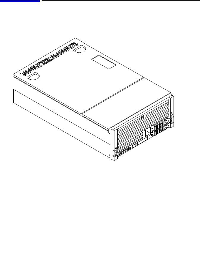
Figure 1-1, Figure 1-2, and Figure 1-3 show the top, front, and rear views of the HP 9000 rp4410 and rp4440 servers.
Figure 1-1 HP 9000 rp4410/rp4440 Server (Top View)
20 |
Chapter 1 |

Overview
Detailed Server Description
Figure 1-2 HP 9000 rp4410/rp4440 Server with Bezel Removed (Front View)
Figure 1-3 HP 9000 rp4410/rp4440 Server (Rear View)
Detailed Server Description
The following sections list information on the main subsystems within the HP 9000 rp4410 and rp4440 servers.
I/O Subsystem
The following is supported on the HP 9000 rp4410 and rp4440 servers:
•PCI-X slots available - 8.
—Two dedicated PCI slots: Slot 1 is for SCSI; slot 2 is for LAN.
—Four hot-pluggable PCI-X 66 MHz 64-bit 3.3V 25W slots with shared busses and I/O. Slots 3 and 4 share capabilities and slots 5 and 6 share capabilities.
—Two hot-pluggable PCI-X 133 MHz 64-bit 3.3V 15W slots dedicated for core I/O.
Chapter 1 |
21 |

Overview
Detailed Server Description
•I/O bandwidth - 4 GBs.
•Pinnacle FXe PCI video card.
•PCI Gigabit, Fast Ethernet Controller with Wake-on-LAN enabled/disabled with BIOS setup.
Internal Core I/O
The following is supported on the HP 9000 rp4410 and rp4440 servers:
•Dual channel SCSI U320 or U160 (PA8800 only) interface or RAID, two internal 68-pin connectors, two 68-pin external connectors.
•SCSI backplane configured as either one or two channels.
•One internal Integrated Drive Electronics (IDE) connector for a slimline optical device (CD and DVD).
•No floppy connector.
•Optional dual channel U320 RAID controller, two internal 68-pin connectors, two 68-pin external connectors (replaces SCSI interface).
External Core I/O
The following is supported on the HP 9000 rp4410 and rp4440 servers:
•Three external serial ports.
•Two external USB ports.
•Two SCSI U320 or U160 68-pin connectors (U160 for PA8800 only).
•One or two 10/100/1000Base-T ethernet LAN connectors for copper cable.
•Two USB 2.0 ports.
•Three DB-9 ports (console, UPS, and modem).
•Optional dual channel U320 RAID controller, two 68-pin external connectors (replaces SCSI interface).
Processors
The following is supported on the HP 9000 rp4410 and rp4440 servers:
•800 MHz/1.5 GB cache or 1 GHz/1.5 GB cache per CPU.
•Both processors are available with 32 MB or 64 MB L2 cache per dual processor module.
•HP 9000 rp4410 server can have one processor or both processors of a single dual processor module enabled, or two processors enabled in each of two dual processor modules.
•HP 9000 rp4440 server can be 1P/2C, 2P/2C, 3P/2C, or 4P/2C.
Memory
The following is supported on the HP 9000 rp4410 and rp4440 servers:
•16 DIMM slots on standard memory extender board.
•32 DIMM slots on optional memory extender board.
•Maximum memory size of 128 GB (4 GB DIMMs on 32-slot memory extender board).
•Supports up to 32 Double Data Rate (DDR) registered ECC memory, in PC2100 DIMMs.
22 |
Chapter 1 |

Overview
Detailed Server Description
•Supported DDR DIMM sizes:
—128 MB, 256 MB, 512 MB, 1 GB, 2 GB, and 4 GB
—Standard 184 pins 2.5V DDR266, CL2, registered, ECC
•133 MHz memory bus frequency, 266 MTransfers/s data, 8.5 GB/s peak data bandwidth.
•DIMMs loaded by quads enable interleaved mode and chip spare.
•Requires that DIMMs within each group of four (quad) be identical.
Cooling
Six cooling fans with N+1 redundancy.
Power Supply Unit
The following is supported on the HP 9000 rp4410 and rp4440 servers:
•One 1200 W hot-swappable power supply.
•Optional second 1200 W hot-swappable power supply for N+1 redundancy.
Front Display Panel, DVD, and Diagnostic Panel
The following is supported on the HP 9000 rp4410 and rp4440 servers:
•Front panel that provides the controls and indicators commonly used for operation.
•DVD+RW drive (with CD-write capability); IDE interface; 48x speed.
•Optional slimline DVD drive.
•Power button and LED indicators for system status.
•LED-based diagnostic panel.
Mass Storage
The following is supported on the HP 9000 rp4410 and rp4440 servers:
•Up to two SCSI hot-pluggable hard disk drives.
•Integrated Ultra-3 SCSI dual channel controller; 80 MB/s transfer rate with two 68-pin connectors. The SCSI backplane is configured as either one or two channels.
•Maximum internal storage of two 73 MB, 15K drives.
•Optional integrated HP RAID controller.
Firmware
Firmware consists of many individually linked binary images that are bound together by a single framework at run time. Internally, the firmware employs a software database called a device tree to represent the structure of the hardware platform and to provide a means of associating software elements with hardware functionality.
Chapter 1 |
23 |

Overview
Dimensions and Values
The firmware incorporates the BCH which provides an interface between the operating system and the platform firmware. BCH uses data tables that contain platform-related information, and boot and run-time service calls available to the operating system and its loader to provide a standard environment for booting.
The firmware supports the HP-UX 11i version 1 (or higher) operating system through the HP 9000 processor family standards and extensions, and has no operating system-specific functionality included. The operating system is presented with the same interface to system firmware, and all features are available to the operating system.
Event IDs for Errors and Events
The server firmware generates event IDs similar to chassis codes for errors, events, and forward progress to the Integrity Integrated Light-Out Management Processor (iLO MP) through common shared memory. The Integrity iLO MP interprets and stores event IDs. Reviewing these events helps you diagnose and troubleshoot problems with the server.
Dimensions and Values
Table 1-1 lists the dimensions and their values of the HP 9000 rp4410 and rp4440 servers.
Table 1-1 |
Server Dimensions and Values |
|
|
|
|
Dimension |
|
Value |
|
|
|
Height |
|
6.8 in (17.3 cm) |
|
|
|
Width |
|
19 in (48.2 cm) |
|
|
|
Depth |
|
27.2 in (69.0 cm) |
|
|
|
Weight |
|
Unloaded 88 lbs (40 kg) |
|
|
Fully loaded 100 lbs (45.4 kg) |
|
|
|
Controls, Ports, and LEDs
This section describes the controls, ports, and LEDs found on the front panel, rear panel, and internal locations of the HP 9000 rp4410 and rp4440 servers.
Front Panel
The front panel of the server provides the controls and indicators commonly used for operation.
24 |
Chapter 1 |
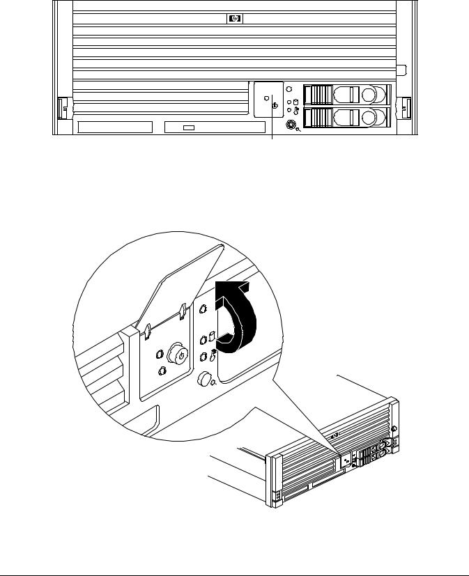
Overview
Controls, Ports, and LEDs
Figure 1-4 shows the control panel on the server front.
Figure 1-4 Control Panel - Front View of Server (with Bezel)
Control Panel
Figure 1-5 shows how to access the control panel. The front control panel access door is on the bezel.
Figure 1-5 Accessing the Control Panel
Chapter 1 |
25 |
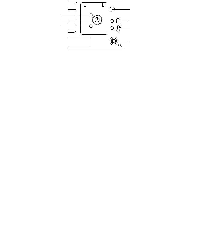
Overview
Controls, Ports, and LEDs
Figure 1-6 shows the control panel LEDs and buttons.
Figure 1-6 Control Panel LEDs and Buttons
|
System LED |
Power LED |
|
Power Button |
Disk LED |
TOC/NMI Button |
Thermal LED |
|
|
|
Locator |
|
Button/LED |
Table 1-2 lists the control panel LED status and descriptions.
Table 1-2 |
Control Panel LED Definitions |
|
|||
|
|
|
|
|
|
LED or |
State |
Flash Rate |
Color |
Description |
|
Button |
|||||
|
|
|
|
||
|
|
|
|
|
|
System LED |
Running |
Steady |
Green |
System normal, OS up and running. |
|
|
|
|
|
|
|
System LED |
Booting |
Flashing at 0.5 Hz |
Green |
OS booting or at BCH. |
|
|
|
|
|
|
|
System LED |
Attention |
Flashing at 1 Hz |
Yellow |
Warning-system needs attention. |
|
|
|
|
|
Redundancy lost, component failure pending. |
|
|
|
|
|
|
|
System LED |
Fault |
Flashing at 2 Hz |
Red |
Hard fault. system halted. |
|
|
|
|
|
|
|
System LED |
Off |
Off |
N/A |
System off. |
|
|
|
|
|
|
|
Power LED |
On |
Steady |
Green |
Power normal. |
|
|
|
|
|
|
|
Power LED |
On |
Flashing at 1 Hz |
Yellow |
Housekeeping voltage present. |
|
|
|
|
|
|
|
Power LED |
Off |
Off |
Off |
Power off. |
|
|
|
|
|
|
|
Disk LED |
|
Flashing at rate of |
Green |
Disk activity. |
|
|
|
disk activity |
|
|
|
|
|
|
|
|
|
Thermal |
OK |
Steady |
Green |
Thermal OK. |
|
LED |
|
|
|
|
|
|
|
|
|
|
|
Thermal |
Warning |
Flashing at 1 Hz |
Yellow |
Thermal warning. |
|
LED |
|
|
|
|
|
|
|
|
|
|
|
Locator |
|
Flashing at 1 Hz |
Blue |
System locator LED can be remotely or |
|
Button or |
|
|
|
locally activated or deactivated. There is also |
|
LED |
|
|
|
a locator button on the rear panel of the |
|
|
|
|
|
server. Pressing either button turns both |
|
|
|
|
|
LEDs on or off and enables or disables the |
|
|
|
|
|
locator function. |
|
|
|
|
|
|
|
26 |
Chapter 1 |

|
|
Overview |
|
|
|
Controls, Ports, and LEDs |
|
Table 1-3 lists LED definitions for the switches and buttons. |
|||
Table 1-3 |
Switch and Button LED Definitions |
||
|
|
|
|
Switch and Button |
Description |
|
|
|
|
|
|
Power Button |
|
Controls the power supply (turns system power on or off) if power is available to |
|
|
|
the power supply. (Controls both power supplies if two are installed). |
|
|
|
If power is off but power is available to the power supplies, pressing the power |
|
|
|
button does the following: |
|
|
|
• From zero to five turns on the power supplies and applies power to server |
|
|
|
circuits. |
|
|
|
• More than five seconds then released, has no effect. |
|
|
|
If power is on and the system is at initial system loader, pressing the power |
|
|
|
button: |
|
|
|
• Momentarily (less than one second) has no effect. |
|
|
|
• More than one second, but less than five seconds—do not use. This initiates |
|
|
|
e-buzzer functions that are not supported in the server. |
|
|
|
• More than five seconds then released causes an immediate hard power off. |
|
|
|
If power is on and the system is at BCH, pressing the power button does the |
|
|
|
following: |
|
|
|
• From zero to five sceonds has no effect. |
|
|
|
• More than five seconds then released causes an immediate hard power off. |
|
|
|
If power is on but the OS has been shut down, pressing the power button: |
|
|
|
• Momentarily (less than one second) has no effect. |
|
|
|
• More than one second, but less than five seconds—do not use. This initiates |
|
|
|
e-buzzer functions that are not supported in the servers. |
|
|
|
• More than five seconds then released causes an immediate hard power off. |
|
|
|
If the OS is running, pressing the power button does the following: |
|
|
|
• Momentarily (less than one second) has no effect. |
|
|
|
• More than one second, but less than five seconds—do not use. This initiates |
|
|
|
e-buzzer functions that are not supported in the servers. |
|
|
|
• More than five seconds then released causes an immediate hard power off. |
|
|
|
|
|
NMI Button |
|
Use a paper clip to press this button. Press the non-maskable interrupt (NMI) |
|
|
|
button before restarting the system after a the system hangs. NMI provides crash |
|
|
|
dump capture capability. Obtain a system hardware status dump to use in root |
|
|
|
cause analysis and debugging. The same function is available with the CM>TC iLO |
|
|
|
MP command. |
|
|
|
|
|
Chapter 1 |
27 |
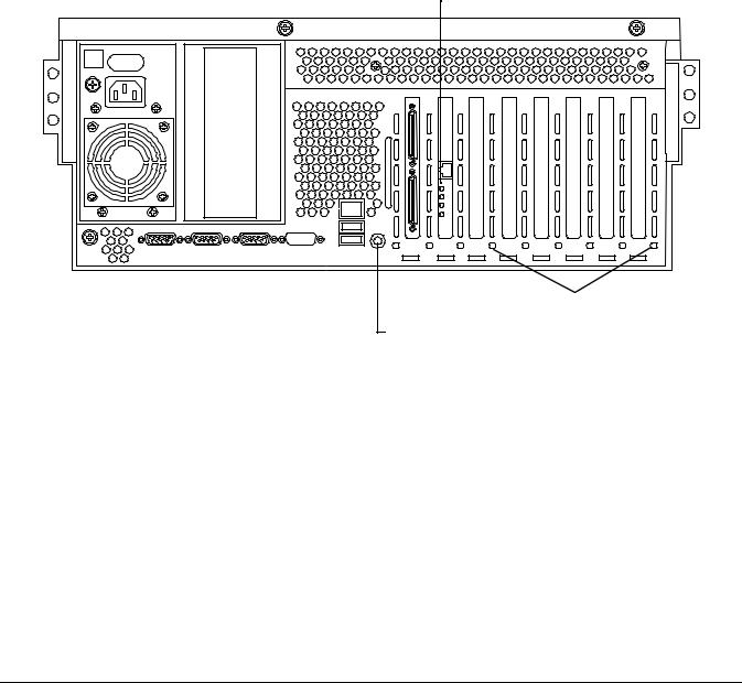
Overview
Controls, Ports, and LEDs
Rear Panel
The server rear panel includes communication ports, I/O ports, ac power connectors, two power supply bays, attention LED indicators for the hot-pluggable PCI boards, and the locator LED button. LEDs located on the rear panel of the server signal the operational status of the following components:
•Power supplies
•iLO MP LAN
•Gigabit Ethernet card LAN
•PCI slots 3-8
Figure 1-7 shows the rear panel LEDs.
Figure 1-7 Rear Panel LEDs
Gigabit Ethernet LAN LEDs
iLO MP LAN LEDs |
|
|
6 PCI Attention LEDs |
|
Locator Button/LED
Power Supply Status LEDs
Each power supply unit has three status LEDs located on the power supply rear side. The front control panel power status LED reports a consolidated status of all power supplies.
28 |
Chapter 1 |
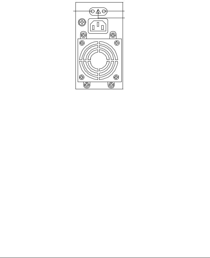
Overview
Controls, Ports, and LEDs
Figure 1-8 show the power supply status LEDs.
Figure 1-8 Power Supply Status LED
Predict Fail |
Power LED (Green) |
|
LED (Amber) |
||
Fail LED (Amber) |
||
|
Table 1-4 lists power supply status LED information.
Table 1-4 |
Power Supply Status LED |
|
||
|
|
|
|
|
Power LED |
Predict Fail |
Fail LED |
|
Status |
(Green) |
LED (Amber) |
(Amber) |
|
|
|
|
|||
|
|
|
|
|
Off |
Off |
Off |
|
No ac power is applied to all PSUs. |
|
|
|
|
|
Off |
Off |
On |
|
No ac power is applied to this PSU only. |
|
|
|
|
|
Blinking |
Off |
Off |
|
ac present and the standby outputs are on. |
|
|
|
|
|
On |
Off |
Off |
|
PSU dc outputs are on and OK. |
|
|
|
|
|
Off |
Off |
On |
|
Power supply failure. |
|
|
|
|
|
On |
Blinking |
Off |
|
Predictive failure. The PSU is about to fail because of a |
|
|
|
|
poorly performing fan. |
|
|
|
|
|
On |
Off |
Blinking |
|
Current limit on 48 VDC output. |
|
|
|
|
|
Chapter 1 |
29 |
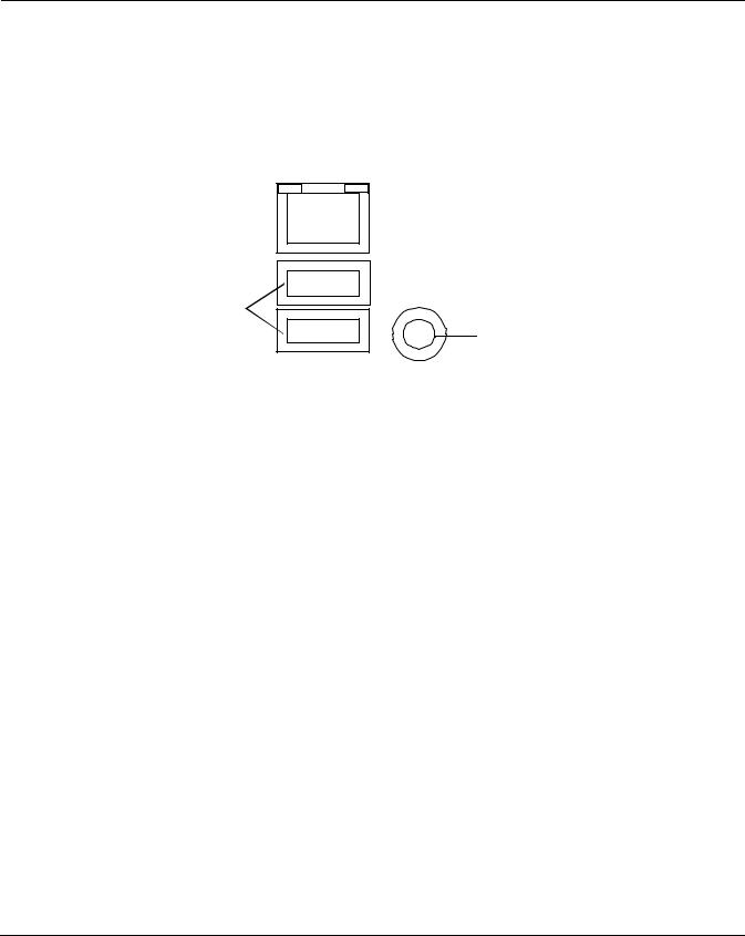
Overview
Controls, Ports, and LEDs
iLO MP LAN LEDs
NOTE |
There are two different iLO MP cards that were installed in this server. They have different |
|
LEDs on them. Both of them are shown below. |
|
|
One of the iLO MP LAN cards has the amber LED on the left abd the green LED on the right. It is shown in Figure 1-9. The internal Integrity iLO MP LAN uses an RJ-45 type connector. This connector has two LEDs (LAN link and LAN activity) that signal status and activity.
Figure 1-9 iLO MP LAN LEDs
100 M Link/Activity, Amber LED |
|
|
|
10 M Link/Activity, Green LED |
|
|
USB Ports
Locator Button and LED
Table 1-5 provides iLO MP LED status descriptions.
Table 1-5 |
iLO MP LED Status Descriptions |
|
|
|
||
|
|
|
|
|
|
|
LED |
|
Condition |
|
|
|
Status |
|
|
|
|
|
|
|
100 M amber |
|
On |
|
Linked at 100 |
MBs. No activity. |
|
|
|
|
|
|
|
|
100 M amber |
|
Blinking |
|
Linked at 100 |
MBs. Activity present. |
|
|
|
|
|
|
|
|
10 M green |
|
On |
|
Linked at 10 |
MBs. No activity. |
|
|
|
|
|
|
|
|
10 M green |
|
Blinking |
|
Linked at 10 |
MBs. Activity present. |
|
|
|
|
|
|
|
|
30 |
Chapter 1 |
Loading...