


®
HP Omnibook 500
Service Manual
For other Service and User Manuals, go to www.ManualDepot.com

Notice
In a continuing effort to improve the quality of our products, technical and environmental information in this document is subject to change without notice.
This manual and any examples contained herein are provided “as is” and are subject to change without notice. Hewlett-Packard Company makes no warranty of any kind with regard to this manual, including, but not limited to, the implied warranties of merchantability and fitness for a particular purpose. Hewlett-Packard Co. shall not be liable for any errors or for incidental or consequential damages in connection with the furnishing, performance, or use of this manual or the examples herein.
Consumer transactions in Australia and the United Kingdom: The above disclaimers and limitations shall not apply to Consumer transactions in Australia and the United Kingdom and shall not affect the statutory rights of Consumers.
© Copyright Hewlett-Packard Company 1998, 1999, 2000, 2001. All rights reserved. Reproduction, adaptation, or translation of this manual is prohibited without prior written permission of HewlettPackard Company, except as allowed under the copyright laws.
The programs that control this product are copyrighted and all rights are reserved. Reproduction, adaptation, or translation of those programs without prior written permission of Hewlett-Packard Co. is also prohibited.
Portions of the programs that control this product may also be copyrighted by Microsoft Corporation, SystemSoft Corp., Phoenix Technologies, Ltd., ATI Technologies Inc., and Adobe Systems Incorporated. See the individual programs for additional copyright notices.
Microsoft®, MS-DOS®, and Windows® are U.S. registered trademarks of Microsoft Corporation. Pentium® and the Intel Inside logo are U.S. registered trademarks and Celeron™ and SpeedStep™ are U.S. trademarks of Intel Corporation. TrackPoint™ is a U.S. trademark of International Business Machines. Adobe® and Acrobat® are trademarks of Adobe Systems Incorporated.
This product incorporates copyright protection technology that is protected by method claims of certain U.S. patents and other intellectual property rights owned by Macrovision Corporation and other rights owners. Use of this copyright protection technology must be authorized by Macrovision Corporation and is intended for home and other limited viewing uses only unless otherwise authorized by Macrovision Corporation. Reverse engineering or disassembly is prohibited.
All certifications may not be completed at product introduction. Check with your HP reseller for certification status.
This equipment is subject to FCC rules. It will comply with the appropriate FCC rules before final delivery to the buyer.
Hewlett-Packard Company
Mobile Computing Division
19310 Pruneridge Ave.
Cupertino, CA 95014, U.S.A.
Edition History
Edition 2 ............................. |
June 2001 |
ii |
HP Omnibook 500 |

Contents
Product Information............................................................................................................ |
1-1 |
Features......................................................................................................................................... |
1-3 |
Operation ...................................................................................................................................... |
1-7 |
Turning the Computer On and Off ........................................................................................ |
1-7 |
Checking the Status of the Computer .................................................................................... |
1-8 |
Using Fn Hot Keys................................................................................................................. |
1-9 |
Resetting the Omnibook ...................................................................................................... |
1-10 |
Docking and Undocking the Computer ............................................................................... |
1-11 |
Connecting a Floppy Disk Drive ......................................................................................... |
1-13 |
Specifications.............................................................................................................................. |
1-14 |
Internal Design............................................................................................................................ |
1-19 |
Removal and Replacement.................................................................................................. |
2-1 |
Disassembly Flowchart................................................................................................................. |
2-2 |
Removing the Main Battery (User-Replaceable).......................................................................... |
2-4 |
Removing a Plug-In Module (User-Replaceable)......................................................................... |
2-5 |
Removing the Hard Disk Drive (User-Replaceable) .................................................................... |
2-6 |
Removing the Power Button Panel (User-Replaceable)............................................................... |
2-9 |
Removing the Keyboard (User-Replaceable) ............................................................................. |
2-10 |
Removing an SDRAM Module (User-Replaceable) .................................................................. |
2-12 |
Removing a System SDRAM Module................................................................................. |
2-12 |
Removing an Expansion SDRAM Module ......................................................................... |
2-13 |
Removing a Mini-PCI Card (certain models only) (User-Replaceable) ..................................... |
2-14 |
Removing the Switchboard PCA (User-Replaceable)................................................................ |
2-16 |
Replacing Small Parts (User-Replaceable)................................................................................. |
2-17 |
Removing the Display Assembly (HP Authorized Service Providers Only).............................. |
2-18 |
Removing the Heatsink/Fan (HP Authorized Service Providers Only)...................................... |
2-21 |
Removing the Top Case (HP Authorized Service Providers Only)............................................ |
2-23 |
Removing the Motherboard or Bottom Case (HP Authorized Service Providers Only) ............ |
2-25 |
Replacing the Motherboard ................................................................................................. |
2-27 |
Replacing the Bottom Case.................................................................................................. |
2-29 |
Repairing the BIOS IC (HP Authorized Service Providers Only).............................................. |
2-32 |
Removing Omnibook Components (HP Authorized Service Providers Only)........................... |
2-34 |
Troubleshooting and Diagnostics ....................................................................................... |
3-1 |
Troubleshooting............................................................................................................................ |
3-2 |
Checking for Customer Abuse............................................................................................... |
3-3 |
Troubleshooting the Problem................................................................................................. |
3-3 |
Verifying the Repair .............................................................................................................. |
3-4 |
Suggestions for Troubleshooting ........................................................................................... |
3-5 |
Diagnostic Tools......................................................................................................................... |
3-19 |
e-DiagTools ......................................................................................................................... |
3-19 |
Power-On Self-Test ............................................................................................................. |
3-26 |
Sycard PCCtest 450/460 CardBus Card (Optional)............................................................. |
3-29 |
Desktop and Windows Management Interfaces (DMI/WMI).............................................. |
3-30 |
BIOS Setup Utility............................................................................................................... |
3-31 |
HP Omnibook 500 |
iii |

Replaceable Parts................................................................................................................. |
4-1 |
Reference Information......................................................................................................... |
5-1 |
Password Removal Policy ............................................................................................................. |
5-1 |
Hewlett-Packard Display Quality Statement ................................................................................. |
5-2 |
Obsolete Parts................................................................................................................................ |
5-4 |
Figures
Figure 1-1. Omnibook — Front View .................................................................................................. |
1-3 |
Figure 1-2. Omnibook — Back View .................................................................................................. |
1-4 |
Figure 1-3. Omnibook — Bottom View............................................................................................... |
1-4 |
Figure 1-4. Expansion Base — Front View ......................................................................................... |
1-5 |
Figure 1-5. Expansion Base — Back View.......................................................................................... |
1-6 |
Figure 1-6. Resetting the Computer ................................................................................................... |
1-10 |
Figure 1-7. Docking the Computer..................................................................................................... |
1-11 |
Figure 1-8. Undocking the Computer................................................................................................. |
1-12 |
Figure 1-9. Manually Undocking the Computer ................................................................................ |
1-12 |
Figure 1-10. Connecting a Floppy Disk Drive ................................................................................... |
1-13 |
Figure 1-11. Replaceable Component Diagram ................................................................................. |
1-19 |
Figure 2-1. Disassembly Flow.............................................................................................................. |
2-2 |
Figure 2-2. Removing the Main Battery............................................................................................... |
2-4 |
Figure 2-3. Releasing the Module ........................................................................................................ |
2-5 |
Figure 2-4. Removing the Hard Disk Drive ......................................................................................... |
2-6 |
Figure 2-5. Removing the Hard Disk Tray........................................................................................... |
2-7 |
Figure 2-6. Removing the Power Button Panel.................................................................................... |
2-9 |
Figure 2-7. Removing the Keyboard Screws...................................................................................... |
2-10 |
Figure 2-8. Removing the Keyboard .................................................................................................. |
2-11 |
Figure 2-9. Removing the System SDRAM Module.......................................................................... |
2-12 |
Figure 2-10. Removing an SDRAM Expansion Module ................................................................... |
2-13 |
Figure 2-11. Removing the Mini-PCI Card (modem card shown) ..................................................... |
2-15 |
Figure 2-12. Routing the Mini-PCI Cables (LAN/modem card shown) ............................................ |
2-15 |
Figure 2-13. Removing the Switchboard PCA (wireless model shown)............................................ |
2-16 |
Figure 2-14. Removing the Display ................................................................................................... |
2-19 |
Figure 2-15. Routing the Display Cable............................................................................................. |
2-19 |
Figure 2-16. Removing the Heatsink/Fan........................................................................................... |
2-21 |
Figure 2-17. Separating the Heatsink and Fan ................................................................................... |
2-22 |
Figure 2-18. Removing the Top Case................................................................................................. |
2-24 |
Figure 2-19. Removing the Motherboard ........................................................................................... |
2-26 |
Figure 2-20. Removing Motherboard Components............................................................................ |
2-27 |
Figure 2-21. Removing Bottom Case Components............................................................................ |
2-30 |
Figure 2-22. Replacing the Docking Doors........................................................................................ |
2-31 |
Figure 2-23. Example of Serial Number Label .................................................................................. |
2-31 |
Figure 2-24. Boot-Block Jumper ........................................................................................................ |
2-33 |
Figure 3-1. Basic Troubleshooting Steps ............................................................................................. |
3-2 |
Figure 3-2. e-DiagTools Screens — Basic and Advanced ................................................................. |
3-19 |
Figure 3-3. Serial and Parallel Loopback Connectors ........................................................................ |
3-21 |
Figure 4-1. Omnibook — Exploded View ........................................................................................... |
4-2 |
iv |
HP Omnibook 500 |

Tables
Table 1-1. Omnibook 500 Series Models ............................................................................................ |
1-1 |
Table 1-2. Product Comparisons ......................................................................................................... |
1-2 |
Table 1-3. Activating Power Modes.................................................................................................... |
1-7 |
Table 1-4. Main Status Lights (front of computer).............................................................................. |
1-8 |
Table 1-5. Keyboard Status Lights ...................................................................................................... |
1-8 |
Table 1-6. Fn Hot Keys ....................................................................................................................... |
1-9 |
Table 1-7. Omnibook 500 Series Specifications ............................................................................... |
1-14 |
Table 1-8. Omnibook 500 Series Accessories................................................................................... |
1-17 |
Table 1-9. Functional Structure ......................................................................................................... |
1-20 |
Table 2-1. Removal Cross-Reference.................................................................................................. |
2-1 |
Table 2-2. Required Equipment........................................................................................................... |
2-3 |
Table 2-3. Recommended Screw Torques........................................................................................... |
2-3 |
Table 2-4. Hard Disk Drive Replacement Part Numbers .................................................................... |
2-6 |
Table 2-5. SDRAM Module Replacement Part Numbers ................................................................. |
2-12 |
Table 2-6. Mini-PCI Card Replacement Part Numbers..................................................................... |
2-14 |
Table 2-7. Replacing Small Parts (User-Replaceable) ...................................................................... |
2-17 |
Table 2-8. Removing Omnibook Components .................................................................................. |
2-34 |
Table 3-1. Scope of Diagnostic Tools ................................................................................................. |
3-5 |
Table 3-2. Troubleshooting Suggestions ............................................................................................. |
3-6 |
Table 3-3. e-DiagTools Error Codes ................................................................................................. |
3-22 |
Table 3-4. POST Terminal-Error Beep Codes .................................................................................. |
3-26 |
Table 3-5. POST Messages ............................................................................................................... |
3-27 |
Table 3-6. Sycard PCCtest Commands ............................................................................................. |
3-29 |
Table 3-7. BIOS Setup Menus and Parameters ................................................................................. |
3-32 |
Table 4-1. Replaceable Parts ............................................................................................................... |
4-3 |
Table 4-2. Accessory Replaceable Parts.............................................................................................. |
4-6 |
Table 4-3. Part Number Reference ...................................................................................................... |
4-7 |
Table 5-1. Omnibook 500 LCD Guidelines (12.1-in TFT, XGA)....................................................... |
5-3 |
Table 5-2. Obsolete Repair Parts......................................................................................................... |
5-4 |
HP Omnibook 500 |
v |

Introduction
This manual provides reference information for use by HP-authorized service personnel in servicing and repairing the HP Omnibook 500.
The manual is designed as a self-paced guide that will train you to service, configure, and repair Omnibook 500 computers. The manual is self-contained, so you can follow it without having equipment available.
The following table lists other sources of information about the computer and related products.
Source |
Address or Number |
Comments |
HP Notebook Web Site |
http://www.hp.com/notebooks |
|
|
(European mirror: |
|
|
http://www.europe.hp.com/notebooks) |
|
HP Partnership Web |
http://partner.americas.hp.com |
Restricted to Authorized Resellers |
|
|
only. |
HP Asia Pacific Channel |
http://www.hp.com.au |
Restricted to DPSP Partners only. |
Support Centre for DPSP |
|
|
Partners |
|
|
HP/MCD Web Site |
http://www.mcd.hp.com |
HP’s internal web site for division |
|
|
information. |
America Online |
Keyword: HP |
Call (800) 827-6364 for membership |
|
|
within the U.S. |
CompuServe |
GO HP |
Call (800) 524-3388 for membership |
|
|
within the U.S. |
HP Support Assist CD-ROM |
(800) 457-1762 |
U.S. and Canada. |
|
(801) 431-1587 |
Outside U.S. and Canada. |
Microsoft Windows manual |
|
Information about Windows operating |
|
|
system. |
Microsoft Web |
http://www.microsoft.com |
Information and updates for Windows |
|
|
operating systems. |
vi |
HP Omnibook 500 |

1
Product Information
The HP Omnibook 500 provides outstanding performance and expandability, in a conveniently portable form. Its high-performance components (including the multimedia expansion base) enable it to perform as a desktop computer or as a portable multimedia presentation tool.
Table 1-1. Omnibook 500 Series Models
Omnibook |
CPU ** |
Display |
Hard |
Drives |
Standard |
Communication |
Product * |
|
|
Drive |
|
SDRAM |
|
F2157x |
Celeron 500 MHz |
12.1" TFT XGA |
7.5 GB |
FDD |
64 MB |
None |
F2158x |
Celeron 500 MHz |
12.1" TFT XGA |
7.5 GB |
FDD |
64 MB |
Modem |
F2159x |
Celeron 500 MHz |
12.1" TFT XGA |
7.5 GB |
Expansion base, |
64 MB |
Modem |
|
|
|
|
FDD, CD-ROM |
|
|
F2160x |
Pentium III 600 MHz |
12.1" TFT XGA |
7.5 GB |
FDD |
64 MB |
None |
F2161x |
Pentium III 600 MHz |
12.1" TFT XGA |
7.5 GB |
FDD |
64 MB |
Modem |
F2162x |
Pentium III 600 MHz |
12.1" TFT XGA |
7.5 GB |
Expansion base, |
64 MB |
Modem |
|
|
|
|
FDD, CD-ROM |
|
|
F2163x |
Pentium III 600 MHz |
12.1" TFT XGA |
10 GB |
FDD |
128 MB |
None |
F2164x |
Pentium III 600 MHz |
12.1" TFT XGA |
10 GB |
FDD |
128 MB |
Modem/LAN |
F2165x |
Pentium III 600 MHz |
12.1" TFT XGA |
10 GB |
Expansion base, |
128 MB |
Modem/LAN |
|
|
|
|
FDD, CD-ROM |
|
|
F2166x |
Pentium III 700 MHz |
12.1" TFT XGA |
20 GB |
FDD |
128 MB |
None |
F2167x |
Pentium III 700 MHz |
12.1" TFT XGA |
20 GB |
FDD |
128 MB |
Modem/LAN |
F2168x |
Pentium III 700 MHz |
12.1" TFT XGA |
20 GB |
Expansion base, |
128 MB |
Modem/LAN |
|
|
|
|
FDD, CD-ROM |
|
|
F3476x |
Celeron 600 MHz |
12.1" TFT XGA |
10 GB |
FDD |
64 MB |
None |
F3477x |
Celeron 600 MHz |
12.1" TFT XGA |
10 GB |
FDD |
64 MB |
Modem/LAN |
F3478x |
Celeron 600 MHz |
12.1" TFT XGA |
10 GB |
Expansion base, |
64 MB |
Modem/LAN |
|
|
|
|
FDD, CD-ROM |
|
|
F3479x |
Pentium III 700 MHz |
12.1" TFT XGA |
20 GB |
FDD |
128 MB |
None |
F3480x |
Pentium III 700 MHz |
12.1" TFT XGA |
20 GB |
FDD |
128 MB |
Modem/LAN |
F3481x |
Pentium III 700 MHz |
12.1" TFT XGA |
20 GB |
FDD |
128 MB |
Modem/LAN/ |
|
|
|
|
|
|
802.11 wireless |
F3482x |
Pentium III 700 MHz |
12.1" TFT XGA |
20 GB |
Expansion base, |
128 MB |
Modem/LAN |
|
|
|
|
FDD, CD-ROM |
|
|
F3483x |
Pentium III 700 MHz |
12.1" TFT XGA |
20 GB |
Expansion base, |
128 MB |
Modem/LAN/ |
|
|
|
|
FDD, CD-ROM |
|
802.11 wireless |
F3484x |
Pentium III 750 MHz |
12.1" TFT XGA |
30 GB |
FDD |
256 MB |
None |
F3485x |
Pentium III 750 MHz |
12.1" TFT XGA |
30 GB |
FDD |
256 MB |
Modem/LAN |
F3486x |
Pentium III 750 MHz |
12.1" TFT XGA |
30 GB |
FDD |
256 MB |
Modem/LAN/ |
|
|
|
|
|
|
802.11 wireless |
F3487x |
Pentium III 750 MHz |
12.1" TFT XGA |
30 GB |
Expansion base, |
256 MB |
Modem/LAN |
|
|
|
|
FDD, CD-ROM |
|
|
F3488x |
Pentium III 750 MHz |
12.1" TFT XGA |
30 GB |
Expansion base, |
256 MB |
Modem/LAN/ |
|
|
|
|
FDD, CD-ROM |
|
802.11 wireless |
This table lists only base product configurations—custom configurations are not included. * For the products listed:
“x” suffix means
“W”, “WT”, “WG”, or “WU” for Windows 98 installed, or
“K”, “KT”, “KG”, or “KU” for Windows 2000 installed (marketing distinction only). ** Intel Mobile Pentium III with SpeedStep Technology or Intel Mobile Celeron processor.
HP Omnibook 500 |
Product Information |
1-1 |

Table 1-2. Product Comparisons
|
Omnibook 500 |
Omnibook 6000 |
Omnibook 900B |
Processor* |
Celeron (500 or 600 MHz) or |
Celeron (550 to 650 MHz) or |
Pentium III (450, 500, 600, or |
|
Pentium III (600 to 750 MHz). |
Pentium III (600 to 850 MHz). |
650 MHz). |
Memory |
64, 128, or 256 MB SDRAM in |
64 or 128 MB SDRAM in |
64 MB SDRAM on |
|
system slot. Expandable to |
system slot. Expandable to |
motherboard. Expandable to |
|
512 MB. |
512 MB. |
160 or 320 MB. |
Display |
12.1-inch TFT XGA display. |
15.0- or 14.1-inch TFT XGA |
13.3-inch TFT XGA or 12.1- |
|
|
or 15.0-inch TFT SXGA+ |
inch TFT SVGA display. |
|
|
display. |
|
Video |
AGP graphics interface. |
AGP graphics interface. |
AGP graphics interface. |
|
4 or 8 MB video RAM with 32- |
4 or 8 MB video RAM with 32- |
4 MB video RAM with 32-bit |
|
or 64-bit graphics interface |
or 64-bit graphics interface |
graphics interface and 64-bit |
|
and 64-bit graphics controller. |
and 64-bit graphics controller. |
graphics controller. |
|
3D and OpenGL graphics |
3D and OpenGL graphics |
3D and OpenGL graphics |
|
support. |
support. |
support. |
|
Up to 16M colors (XGA). |
Up to 16M colors (XGA). |
Up to 16M colors (XGA). |
|
Zoomed Video enabled. |
Zoomed Video enabled. |
Zoomed Video enabled. |
Operating System |
Windows 98 or Windows 2000 |
Windows 95, Windows 98, or |
Windows 95, Windows 98, |
|
preinstalled. |
Windows 2000 preinstalled. |
Windows NT, or Windows |
|
|
|
2000 preinstalled. |
HP Toptools |
HP Toptools 5.0. |
HP Toptools 4.5 to 5.0. |
HP Toptools 3.0 to 5.0. |
|
|
|
|
Power Management |
APM 1.2. |
APM 1.2. |
APM 1.2. |
|
ACPI compliant. |
ACPI compliant. |
ACPI compliant. |
Power States |
On, Standby, Hibernate, Off. |
On, Display-off, Standby, |
On, Display-off, Standby, |
|
|
Hibernate, Off. |
Hibernate, Off. |
* Intel Mobile Pentium or Mobile Celeron Processor. Dual-speed processors use Intel SpeedStep Technology.
1-2 |
Product Information |
HP Omnibook 500 |
Features
The following three illustrations show the computer’s main external features. For an exploded view of the computer, see page 4-2.
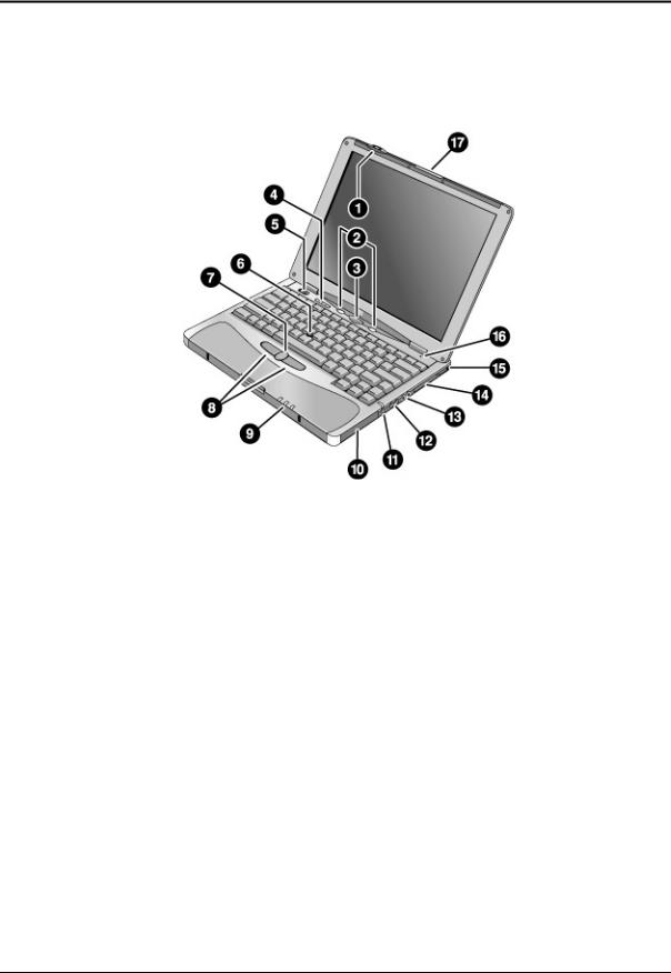
Figure 1-1. Omnibook — Front View
1.Wireless on-off button and indicator light (on certain models).
2.Left and right One-Touch buttons (programmable).
3.Sleep button. Suspends and resumes operation.
4.Keyboard status lights: Caps Lock, Num Lock, Keypad Lock, Scroll Lock.
5.Power slide button. Turns the computer on and off.
6.Pointing stick (pointing device).
7.Scroll button.
8.Left and right click buttons.
9.Main status lights: power mode, hard disk activity, main battery charge.
10.Hard disk drive.
11.Audio-off button and audio-off light.
12.Volume control.
13.Audio jacks: audio out (headphones), external microphone.
14.PC Card slot.
15.PC Card eject button.
16.Built-in microphone.
17.Latch for opening the computer.
HP Omnibook 500 |
Product Information |
1-3 |
|
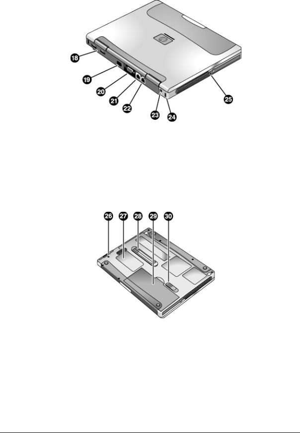
Figure 1-2. Omnibook — Back View |
18. Universal serial bus ports (USB). |
22. LAN port (on certain models). |
19. Infrared port (on certain models). |
23. AC adapter jack. |
20. External monitor port. |
24. Kensington lock slot (security connector). |
21. Modem port (on certain models). |
25. System-off switch. |
|
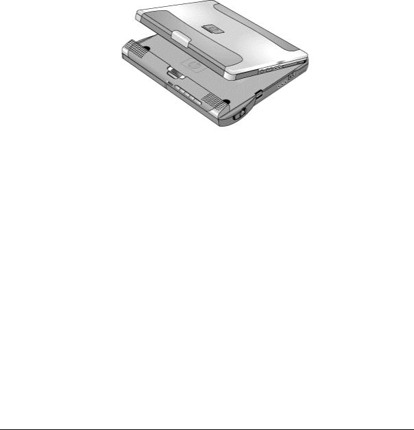
Figure 1-3. Omnibook — Bottom View |
26. Hard disk drive retaining screw. |
29. Main battery. |
27. SDRAM cover. |
30. Main battery latch. |
28. Docking port. |
|
1-4 |
Product Information |
HP Omnibook 500 |
The following two illustrations show the main external features of the expansion base.
Figure 1-4. Expansion Base — Front View
1.Docking connector.
2.Status panel.
3.Status panel button.
4.Speaker (one on each side).
5.Left plug-in module bay. Can contain a CD-ROM or DVD drive, floppy disk drive, secondary battery, or other plug-in module.
6.CD status light.
7.CD player power button.
8.CD player controls: previous track, play/pause, stop, next track, volume.
9.Right plug-in module bay. Used with CD player controls.
10.Module eject latch (one on each side).
11.Undock switch.
12.Audio jacks: audio out (headphones), external microphone, audio line in.
13.Kensington lock slot (security connector).
14.Emergency undock latch.
HP Omnibook 500 |
Product Information |
1-5 |

Figure 1-5. Expansion Base — Back View
15.Universal serial bus ports (USB).
16.S-video (TV out) port.
17.Serial port (COM1).
18.Parallel port (LPT1). Use this port for a parallel printer or other parallel device.
19.External monitor port.
20.PS/2 mouse port.
21.PS/2 keyboard port.
22.LAN port (works only if the computer has a built-in LAN port).
23.AC adapter jack.
1-6 |
Product Information |
HP Omnibook 500 |

Operation
This section gives an overview of the operation of the computer and expansion base.
Turning the Computer On and Off
You can start and stop the computer using its blue sleep button. However, at times you may want to use other methods to start or stop the computer, depending on power considerations, types of active connections, and start-up time.
Table 1-3. Activating Power Modes
Power mode |
To enter this mode |
To turn on again |
On mode |
Press the blue sleep button. |
|
Power mode status light is green. |
|
|
Standby mode |
Press blue sleep button |
Press the blue |
Saves significant power. |
–or– |
sleep button to |
Turns off the display and other components. |
click Start, Shutdown, Standby |
display your current |
Maintains current session in SDRAM. |
–or– |
session. |
Restarts quickly. |
allow timeout. |
|
Restores network connections. |
|
|
Power mode status light is amber. |
|
|
Hibernate mode |
Press Fn+F12 |
Press the blue |
Saves maximum power. |
–or– |
sleep button to |
Saves current session to disk, then shuts down. |
Click Start, Hibernate |
restart and restore |
Restores network connections. |
(Windows 98) |
your previous |
Power mode status light is off. |
–or– |
session. |
|
Click Start, Shut Down, Hibernate |
|
|
(Windows 2000) |
|
|
–or– |
|
|
allow timeout. |
|
Shut down (off) |
Click Start, Shut Down, Shut down |
Press the blue |
Saves maximum power. |
(recommended) |
sleep button to |
Turns off without saving current session. |
–or– |
restart with a new |
At startup, resets everything, starts a new session, |
slide the power button. |
session. |
and restores network connections. |
|
|
Power mode status light is off. |
|
|
HP Omnibook 500 |
Product Information |
1-7 |
Checking the Status of the Computer
The main status lights on the front of the computer report the computer’s power mode and hard drive activity, and the status of the main battery.
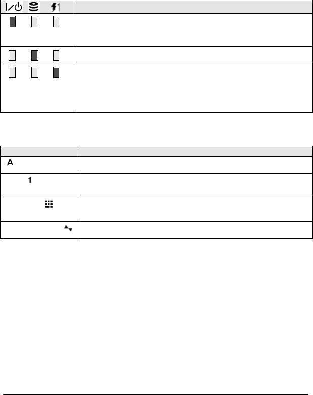
Table 1-4. Main Status Lights (front of computer)
Meaning
Power mode
On: the computer is on (even if the display is off).
Blinking: the computer is in Standby mode. (Steady amber light on some models.)
Off: computer is off or in Hibernate mode.
Hard disk drive activity
Blue: the computer is accessing the hard disk drive.
Main battery charge status
Green: the AC adapter is connected and the battery is fully charged. Amber: the AC adapter is connected and the battery is charging.
Blinking. the AC adapter is connected and the battery is missing or has a fault. (Steady red light on some models.)
Off: the AC adapter is not connected.
The keyboard status lights indicate the status of the keyboard locks.
Table 1-5. Keyboard Status Lights
Meaning
Caps Lock
Caps Lock is active.
Num Lock
Num Lock is active (Fn+F9). (The Keypad Lock must also be on to use the embedded keypad.)
Keypad Lock
The embedded keypad is active (Fn+F8). Num Lock must also be on for the numeric keys—otherwise, cursor control is active.
Scroll Lock
Scroll Lock is active (Fn+F10).
Battery Status
Every main battery and secondary battery plug-in module has five lights on its back (connector) side that indicate its charge level. To view these lights, press the pad next to them. The number of lights that turn on indicates the battery’s charge.
1-8 |
Product Information |
HP Omnibook 500 |

Using Fn Hot Keys
The combination of the Fn key plus another key creates a hot key—a shortcut key sequence—for various system controls. To use a hot key, press and hold Fn, press the appropriate second key, then release both keys.
External PS/2 keyboards support only Fn+F5, Fn+F7, and Fn+F12. To use these, press and hold left CTRL+left ALT, press the appropriate second key, then release both keys.
External USB keyboards do not support Fn hot keys.
|
Table 1-6. Fn Hot Keys |
Hot Key |
Effect |
Fn+F1 |
Decreases the display brightness. |
Fn+F2 |
Increases the display brightness. |
Fn+F5 |
Toggles among the built-in display, an external display, and simultaneous display on |
|
both. |
Fn+F7 |
Audio mute. |
Fn+F8 |
Toggles the built-in keypad on and off. Does not affect an external keyboard. If Num |
|
Lock is on, then the numeric functions are active; otherwise, cursor control is active (as |
|
marked on an external keyboard). |
Fn+F9 |
Toggles Num Lock on and off. |
Fn+F10 |
Toggles Scroll Lock on and off. |
Fn+F11 |
Pause. |
Fn+F12 |
Enters Hibernate mode. |
Fn+HOME |
Prints screen. |
Fn+UP ARROW* |
Increases sound volume. |
Fn+DOWN ARROW* |
Decreases sound volume. |
* Only if marked on the ARROW keys.
HP Omnibook 500 |
Product Information |
1-9 |
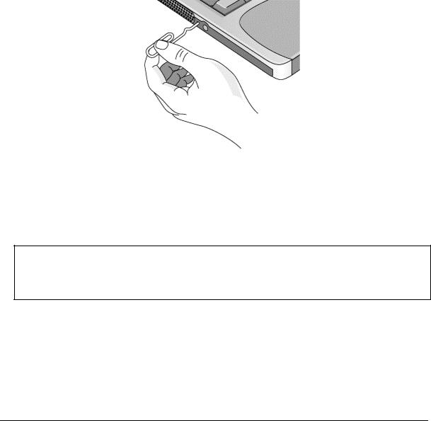
Resetting the Omnibook
Occasionally, Windows or the computer may stop responding, so that you cannot turn the computer off. If this happens, try the following in the order listed:
•If possible, shut down Windows: press CTRL+ALT+DEL, then click Shut Down. Press the blue sleep button to restart.
•Slide and hold the power button for four seconds, until the display shuts down, then press the blue sleep button to restart.
•Use a straightened paper clip to press the system-off switch on the left side of the computer. Press the blue sleep button to restart.
•Undock the computer if docked, unplug the AC adapter, remove the main battery, then insert a straightened paper clip into the computer’s system-off switch. Press the blue sleep button to restart.
Figure 1-6. Resetting the Computer
Resetting an Expansion Base
To reset an expansion base—and the computer, if docked (see the following page)—insert a straightened paper clip into the reset hole on the bottom of the expansion base. You can also reset the expansion base by undocking the computer and removing all AC and battery power from the base.
Note
To boot from a CD-ROM or DVD drive in the expansion base, insert a bootable CD (such as the Recovery CD) into the drive, then restart the computer. Press ESC when the HP logo appears during reboot, then select the CD-ROM/DVD drive as the temporary boot device.
1-10 Product Information |
HP Omnibook 500 |
Docking and Undocking the Computer
You can dock or undock the computer in any power state: on, off, Standby mode, or Hibernate mode. Make sure, however, that the computer is not entering or resuming from Standby or Hibernate mode when you dock or undock, or the computer could lock up.
Docking the Computer
By default, the computer automatically turns on when you dock it. If you have trouble inserting the computer or the docking latches stick, use the emergency undock latch.
1.Optional: plug the AC adapter into the expansion base.
2.Insert the back of the computer into the expansion base, then lower the front end into the base and press down firmly until it clicks into place.
Figure 1-7. Docking the Computer
HP Omnibook 500 |
Product Information 1-11 |

Undocking the Computer
1.Press the undock switch. (You can use the undock switch when the computer is on, off, or in Standby or Hibernate mode.)
–or–
Click Start, Eject PC.
Figure 1-8. Undocking the Computer
You may need to wait 10 seconds or more for the computer to undock—the computer may not respond while it is updating its configuration.
2.If the computer will not undock using the undock switch or Start menu, use the emergency undock latch: slide the button down, then move the entire latch forward.
Figure 1-9. Manually Undocking the Computer
1-12 Product Information |
HP Omnibook 500 |
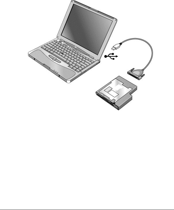
Connecting a Floppy Disk Drive
When needed, you can connect the floppy disk drive to one of the computer’s USB ports.
•Connect the USB floppy drive cable directly to the floppy drive and to the USB port.
You cannot use the USB floppy cable to connect to any other type of drive module, such as a CD-ROM or DVD drive. The USB cable is for floppy drives only.
Figure 1-10. Connecting a Floppy Disk Drive
HP Omnibook 500 |
Product Information 1-13 |

Specifications
The following tables list the specifications for the computer and its accessories. These are subject to change: for the latest versions, see the HP Notebook web site (www.hp.com/notebooks).
|
Table 1-7. Omnibook 500 Series Specifications |
Physical Attributes |
Computer: |
|
Size: 278 × 222 × 25 mm (10.9 × 8.7 × 1.0 in). |
|
Weight: 1.5 kg (3.4 lb) minimum, depending on model. |
|
Magnesium casing with rubberized grip surfaces. |
|
Computer docked in expansion base: |
|
Size: 298 × 257 × 45 mm (11.7 × 10.1 × 1.8 in). |
|
Weight: 2.4 kg (5.4 lb) minimum, depending on model. |
Processor and |
600to 750-MHz Intel Mobile Pentium III processor with Speed Step technology with |
Bus Architecture |
256-KB four-way set-associative L2 cache. |
|
–or– |
|
500to 600-MHz Intel Celeron processor with 128-KB four-way set-associative L2 |
|
cache. |
|
1.35/1.1-V (Pentium III) or 1.35-V (Celeron) core, 2.5-V external, low-power |
|
processor. |
|
32-KB (16-KB instruction, 16-KB data) L1 cache. |
|
32-bit PCI bus. |
Graphics |
12.1-inch XGA active-matrix (TFT) display (1024 × 768 × 16M colors). |
|
Zoomed Video support for PC Card slot. |
|
3D and OpenGL graphics support. |
|
Celeron models: |
|
ATI Mobility M graphics accelerator with 4-MB display RAM, 2x AGP graphics |
|
capability. |
|
Pentium III models: |
|
ATI Mobility M1 graphics accelerator with 8-MB display RAM, 2x AGP graphics |
|
capability. |
Power |
Rechargeable lithium-ion battery (11.1 or 14.8 Vdc) with LED charge-level gauge. |
|
Battery life (single battery): over 4 hours typical (varies with model and usage). |
|
Fast battery recharge: approximately 2 hours. |
|
Low-battery warning. |
|
Suspend/resume capability. |
|
Universal AC adapter: 100–240 Vac (50/60 Hz) input, 19 Vdc output, 60–65 W. |
|
Optional secondary battery available for expansion base module bays. |
Mass Storage |
Computer: |
|
7.5- to 30-GB removable hard disk drive. |
|
1.44-MB floppy drive module. |
|
Expansion base: |
|
Two bays for plug-in drive modules. |
|
Optional drive modules available. |
SDRAM |
Two slots for SDRAM expansion (SODIMM, PC100 or higher) up to 512 MB. |
|
64-, 128-, or 256-MB SDRAM installed in system SDRAM slot under keyboard. |
|
100-MHz SDRAM bus. |
1-14 Product Information |
HP Omnibook 500 |
Audio System |
Computer: |
|
Built-in speaker. |
|
3D-enhanced PCI bus audio with Zoomed Video support. |
|
Built-in microphone. |
|
Separate audio-off button with indicator light. |
|
Headphone-out and microphone-in. |
|
Expansion base: |
|
CD player (can play with or without computer docked). |
|
Stereo sound via three built-in speakers. |
|
Analog pass-through from the computer. |
|
Headphone-out, microphone-in, and audio line-in. |
Keyboard and |
84/85/87-key touch-type QWERTY keyboard with 101/102 key emulation. |
Pointing Device |
Embedded numeric keypad. |
|
12 function (Fn) keys. |
|
Two user-programmable One-Touch buttons. |
|
Pointing stick (TrackPoint technology licensed from IBM). |
|
Left and right click buttons, center scroll button. |
LAN (3Com) |
Ethernet 10Base-T (10 Mbps) and 100Base-TX (100 Mbps) support. |
|
Supports wake-on-LAN, fast IP, DMI, dRMON. |
|
MBA (Managed Boot Agent) support for PXE/BINL, BOOTP, NCP/IPX, DHCP. |
Modem (3Com, |
Data speed: 56 Kbps (V.90) maximum. |
US Robotics) |
Fax speed: 14.4 Kbps, Class 1 and 2. |
|
Modulation: V.21, V.22, V.22bis, V.23, V.32, V.32bis, V.34, V.90, X2, Bell 103, |
|
Bell 212A. |
|
Synchronous transfer: V.80. |
|
Compression: V.42bis, MNP5. |
|
Error correction: V.42, MNP2-4. |
|
Fax: Group 3 fax, Class 1. V.17, V.27ter, V.29, V.21 channel 2. |
|
Local modem adapter provided for non-U.S. regions. |
802.11 Wireless LAN |
Radio: IEEE 802.11b compliant, ISM frequency band, Direct Sequence Spread |
|
Spectrum. |
|
Operating frequency: within 2.4–2.497 GHz, depending on country (US, Canada, |
|
ETSI, Japan). |
|
Channels: up to 13 channels (22 MHz bandwidth) that can overlap and are |
|
dependent upon the country configuration. |
|
Data rate: 1, 2, 5.5, or 11 Mbps. |
|
RF output: 15 dBm typical (approx. 30 mW), 16 dBm max (approx. 40 mW). |
|
Sensitivity: –84 dBm. |
|
Range: up to 100 m (300 ft) or more, depending on environment and conditions. |
|
On-off button with power indicator. |
|
USB interface. |
Input/Output |
Computer: |
|
Two universal serial bus (USB) ports. |
|
15-pin VGA video-out with DDC support. (Resolution up to 1600 × 1200 × 64K or |
|
16M colors. Refresh rate of 60 to 100 Hz, depending on resolution and color depth. |
|
Dual display.) |
|
4-Mbps IrDA-compliant infrared port. |
|
Expansion base: |
|
Two universal serial bus (USB) ports. |
|
9-pin, 115,200-bps serial (16550 UART). |
|
25-pin bi-directional ECP/EPP parallel. |
|
15-pin VGA video-out with DDC support. (Resolution up to 1600 × 1200 × 64K or |
|
16M colors. Refresh rate of 60 to 100 Hz, depending on resolution and color depth. |
|
Dual display.) |
|
S-video (TV out). |
|
PS/2 keyboard and PS/2 mouse. |
Expandability |
Computer: |
|
One Type II 16-/32-bit PC Card slot (3.3 V and 5 V support). |
|
CardBus enabled, Zoomed Video support. |
|
Expansion base: |
|
Two plug-in module bays for accessory modules. |
HP Omnibook 500 |
Product Information 1-15 |

Security Features |
User and administrator passwords. |
|
System, hard drive, and docking passwords. |
|
PC identification displayed at boot. |
|
DMI-accessible electronic serial number. |
|
Kensington MicroSaver lock slot. |
Environmental Limits |
Operating temperature: 5 to 35 ° C (41 to 95 ° F). |
|
Operating humidity: 20 to 90 percent RH, 5 to 35 ° C (41 to 95 ° F). |
|
Operating altitude: up to 3000 m (10,000 ft) at 25 ° C (77 ° F). |
|
Storage temperature: –20 to 50 ° C (–4 to 122 ° F). |
Major ICs |
Computer: |
|
CPU: Intel Mobile Pentium III or Celeron processor. |
|
South Bridge: PIIX4M. |
|
Display controller: ATI Mobility M or M1. |
|
Audio controller: ESS Maestro-3E and ESS ES1921. |
|
CardBus controller: TI PCI 1410. |
|
Keyboard/embedded controller: National NS87570. |
|
Super I/O: National NS97338. |
|
Expansion base: |
|
Embedded controller: National NS87570. |
|
PCI IDE controller: CMD PCI-648. |
|
Audio controller: OZ163. |
1-16 Product Information |
HP Omnibook 500 |

Table 1-8. Omnibook 500 Series Accessories
Accessory |
Description |
Omnibook |
Compat. |
Compat. |
|
|
500 |
6000 |
900B |
Memory |
|
|
|
|
|
|
|
|
|
F1457B |
64-MB SDRAM module (PC100) |
• |
• |
• |
|
|
|
|
|
F1457C |
64-MB SDRAM module (PC133) |
• |
• |
• |
|
|
|
|
|
F1622B |
128-MB SDRAM module (PC100) |
• |
• |
• |
|
|
|
|
|
F1622C |
128-MB SDRAM module (PC133) |
• |
• |
• |
|
|
|
|
|
F1654A |
256-MB SDRAM module (PC100) |
• |
• |
• |
|
|
|
|
|
F1654C |
256-MB SDRAM module (PC133) |
• |
• |
• |
|
|
|
|
|
Hard Drives |
|
|
|
|
0950-4030 |
7.5-GB hard disk drive |
• |
|
|
|
|
|
|
|
0950-4011 |
7.5-GB hard disk drive |
• |
|
|
|
|
|
|
|
0950-3934 |
10-GB hard disk drive |
• |
|
|
|
|
|
|
|
0950-3985 |
10-GB hard disk drive |
• |
|
|
|
|
|
|
|
0950-3935 |
20-GB hard disk drive |
• |
|
|
|
|
|
|
|
0950-4162 |
30-GB hard disk drive |
• |
|
|
|
|
|
|
|
Multimedia Expansion Base |
|
|
|
|
|
|
|
|
|
F2096B |
Multimedia expansion base |
• |
|
|
|
|
|
|
|
Plug-in Modules |
|
|
|
|
|
|
|
|
|
F2008A |
Floppy disk drive cable (parallel) |
• |
• |
|
|
|
|
|
|
F2009A |
Zip drive module |
• |
• |
|
|
|
|
|
|
F2013A |
Floppy disk drive module |
• |
• |
|
|
|
|
|
|
F2015A |
DVD drive module |
• |
• |
|
|
|
|
|
|
F2017A |
CD-ROM drive module |
• |
• |
|
|
|
|
|
|
F2018A |
Second hard drive module with 18-GB hard drive |
• |
• |
|
|
|
|
|
|
F2018B |
Second hard drive module with 20-GB hard drive |
• |
• |
|
|
|
|
|
|
F2018C |
Second hard drive module with 30-GB hard drive |
• |
• |
|
|
|
|
|
|
F2022A |
LS-120 drive module |
• |
• |
|
|
|
|
|
|
F2026A |
CD-RW drive module |
• |
• |
|
|
|
|
|
|
F2101A |
USB floppy disk drive cable |
• |
|
|
|
|
|
|
|
F2107A |
DVD-ROM/CD-RW drive module |
• |
• |
|
|
|
|
|
|
Power Options |
|
|
|
|
F1454A |
60W AC adapter |
• |
• |
• |
|
|
|
|
|
F1455A |
75W auto/airline power adapter (12 V) |
• |
• |
• |
|
|
|
|
|
F1781A |
60W Ultraslim AC adapter |
• |
• |
• |
|
|
|
|
|
F2011A |
External lithium-ion battery charger for F2014A |
• |
• |
|
|
|
|
|
|
F2014A |
Lithium-ion secondary battery |
• |
• |
|
|
|
|
|
|
F2098A |
Main battery (11.1 V, 6-cell) |
• |
|
|
|
|
|
|
|
HP Omnibook 500 |
Product Information 1-17 |

Accessory |
Description |
Omnibook |
Compat. |
Compat. |
|
|
500 |
6000 |
900B |
8120-6312 |
Replacement power cord (Australia) |
• |
• |
• |
8120-6313 |
Replacement power cord (U.S./Canada/Taiwan) |
|
|
|
8120-6314 |
Replacement power cord (Europe) |
|
|
|
8120-6316 |
Replacement power cord (Japan) |
|
|
|
8120-6317 |
Replacement power cord (India/South Africa) |
|
|
|
8120-8367 |
Replacement power cord (Argentina) |
|
|
|
8120-8373 |
Replacement power cord (China) |
|
|
|
8120-8452 |
Replacement power cord (Chile) |
|
|
|
8120-8699 |
Replacement power cord (UK [EPSR] |
|
|
|
|
Hong Kong/Singapore) |
|
|
|
PC Cards |
|
|
|
|
F1623A |
10/100-Mbps Ethernet + 56-Kbps modem PC |
• |
• |
• |
|
Card by Xircom |
|
|
|
F1625A |
56-Kbps global modem PC Card by Xircom |
• |
• |
• |
|
|
|
|
|
F1626B |
10/100-Mbps Ethernet PC Card by 3Com |
• |
• |
• |
|
|
|
|
|
F1627A |
56-Kbps U.S. modem PC Card by Xircom |
• |
• |
• |
|
|
|
|
|
F1782A |
10/100-Mbps Ethernet + 56-Kbps modem PC |
• |
• |
• |
|
Card by 3Com |
|
|
|
F1985A |
10/100-Mbps USB-Ethernet adapter by 3Com |
• |
• |
• |
|
|
|
|
|
F2135B |
802.11b wireless LAN access point for use |
• |
• |
• |
|
with F2136A |
|
|
|
F2136A |
802.11b wireless LAN PC Card |
• |
• |
• |
|
|
|
|
|
F2138A |
HP/Sierra Wireless Air Card 300 CDPD PC Card |
• |
• |
• |
|
|
|
|
|
F2196A |
Bluetooth PC Card by 3Com |
• |
• |
• |
|
|
|
|
|
1-18 Product Information |
HP Omnibook 500 |
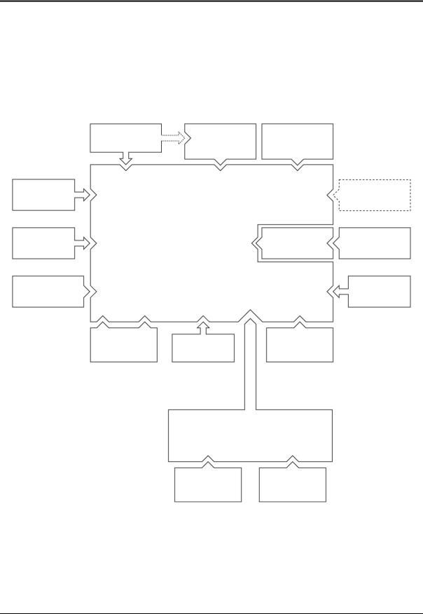
Internal Design
The motherboard PCA is the central component of the computer’s design, and plays a role in virtually all system functions. Most components connect directly to the motherboard.
The following figure shows the connections among the replaceable components in the computer and expansion base. In addition, Table 1-9 on page 1-20 lists the roles that these components play in the functional subsystems of the computer and expansion base.
Display |
|
(1) |
|
|
|
Switchboard |
Mini-PCI |
|
|
Assembly |
|
|||
PCA |
Card |
|
||
|
|
|
||
Heatsink/fan |
|
|
|
PC Card |
|
Motherboard |
|
|
|
Top Case |
|
|
HDD/LED |
Hard Disk Drive |
|
|
Flex Cable |
||
|
|
|
|
|
Expansion |
|
|
|
|
SDRAM |
|
|
|
Speaker |
Module |
|
|
|
|
Battery |
|
Keyboard (with |
System SDRAM |
|
|
Module |
|
||
|
|
pointing stick) |
|
|
|
|
|
|
|
(1) Wireless models only
Expansion Base
Plug-in Module |
Plug-in Module |
Figure 1-11. Replaceable Component Diagram
HP Omnibook 500 |
Product Information 1-19 |

|
|
Table 1-9. Functional Structure |
Function |
Components Used |
Component Roles |
Bootup |
Motherboard |
Main processor, primary system circuitry. |
|
Hard disk drive |
First source of disk-based startup code. |
|
Removable device |
Second source of disk-based startup code. |
|
|
|
Processor |
Motherboard |
Main processor, numeric data processor, L1 and L2 cache, primary system |
|
|
circuitry. |
Memory |
Motherboard |
Video RAM. |
|
SDRAM modules |
Changeable SDRAM (2 slots). |
Power |
Main battery |
Power storage. |
|
Motherboard |
AC adapter socket, power switch, lid switch, system-off switch, power supply, |
|
|
power control circuitry. |
|
Switchboard PCA |
Sleep switch. |
|
Backup battery |
Provides short-term power to maintain memory while swapping main battery. |
|
CMOS battery |
Maintains system data stored in CMOS RAM. |
|
Expansion base |
AC adapter socket, system-off switch, power supply, power control circuitry. |
|
AC adapter |
AC-to-DC converter. |
|
|
|
Display |
Motherboard |
PCMCIA/Zoomed Video controller, display drivers, LVDS processing, |
|
|
display/graphics controller, video RAM. |
|
Display assembly |
Display output, backlight, power converter for backlight. |
Hard disk |
Motherboard |
Hard disk controller. |
|
HDD/LED flex cable |
Hard disk signal pass-through. |
|
Hard disk drive |
Hard disk mechanism. |
Keyboard |
Motherboard |
Keyboard BIOS, keyboard controller. |
|
Keyboard |
Key switches. |
|
Switchboard PCA |
One-Touch switches. |
Pointer |
Motherboard |
Keyboard BIOS, pointing stick controller (PS/2 output), keyboard controller. |
|
Keyboard |
Pointing stick sensor. |
|
Top case |
Click buttons, scroll button. |
Audio |
Motherboard |
Audio controller, audio decoder, speaker amplifier, Zoomed Video controller, |
|
|
microphone, external audio jacks, headphone amplifier, audio-off switch. |
|
Bottom case |
Speaker. |
|
Expansion base |
CD player, audio circuitry, speakers. |
Status |
Motherboard |
LED circuitry, keyboard controller. |
|
Switchboard PCA |
Keyboard LEDs. |
|
HDD/LED flex cable |
Main status LEDs. |
|
Top case |
Audio-off LED. |
|
Expansion base |
Status panel. |
Serial |
Motherboard |
I/O controller. |
|
Expansion base |
Serial connector. |
Parallel |
Motherboard |
I/O controller. |
|
Expansion base |
Parallel connector. |
Infrared |
Motherboard |
I/O controller, infrared transmitter/receiver. |
Wireless |
Display assembly |
Radio PCA, circuitry, and antennas, on-off button, and indicator light. |
|
Motherboard |
I/O controller. |
|
Switchboard PCA |
Power/signal pass-through. |
PS/2 ports |
Motherboard |
Keyboard controller. |
|
Expansion base |
PS/2 connectors. |
USB |
Motherboard |
Bus controller (South Bridge), USB connectors, overload switch. |
|
Expansion base |
USB connectors, overload switch. |
Docking |
Motherboard |
Docking logic, docking connector. |
|
Expansion base |
Docking connector, undock switch, emergency undock latch. |
PC Card |
Motherboard |
PC Card controller, PC Card connector. |
1-20 Product Information |
HP Omnibook 500 |
2
Removal and Replacement
This chapter tells you how to remove and replace the computer’s removable components and assemblies. The items marked by • in the following table are user-replaceable.
Table 2-1. Removal Cross-Reference
Battery, backup (page 2-34). |
• Feet, rubber (page 2-17). |
Battery, CMOS (page 2-34). |
Guide, hard drive (page 2-34). |
• Battery, main (page 2-4). |
Heatsink/fan (page 2-21). |
Cable, hard drive/LED flex (page 2-34). |
• Keyboard (page 2-10). |
• Card, mini-PCI (page 2-14). |
• Module, plug-in (page 2-5). |
Case, bottom (page 2-25). |
• Module, SDRAM (page 2-12). |
Case, top (page 2-23). |
Panel, audio/PCMCIA (page 2-35). |
• Cover, SDRAM (page 2-17). |
Panel, mini-PCI (page 2-35). |
• Covers, display hinge (page 2-17). |
• Panel, power button (page 2-9). |
• Covers, display screw (page 2-17). |
PCA, motherboard (page 2-25). |
• Cover, Trackpoint (page 2-17). |
• PCA, switchboard (page 2-16). |
Display assembly (page 2-18). |
Plate, EMI (page 2-35). |
Doors, docking (page 2-31). |
Speaker (page 2-35). |
• Drive, hard disk (page 2-6). |
• Tray, hard disk drive (page 2-7). |
|
|
Caution
Always provide proper grounding when performing repairs. Without proper grounding, an electrostatic discharge can damage the computer or expansion base and their components.
Notes
Reassembly steps are the reverse of the removal/disassembly steps. Reassembly notes are included at the end of each removal procedure.
 Symbols like this throughout this chapter show approximate full-size screw outlines. You can use these to verify the sizes of screws before you install them. Installing a wrong-size screw can damage the unit. (The symbol at the left represents an M2.5×5mm T-head screw.)
HP Omnibook 500 |
Removal and Replacement |
2-1 |
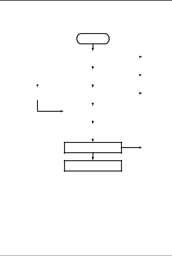
Disassembly Flowchart
The following diagram shows the general “path” you will use in disassembling the computer to access components.
Start
|
Main battery, AC adapter |
|
• Expansion SDRAM module* |
|
|
|
• Hard disk drive* |
||
|
|
|
|
|
|
|
|
|
• Switchboard PCA* ‡ |
|
|
|
|
|
|
|
|
|
|
|
Power button panel |
|
||
|
|
|||
|
|
|
|
|
|
|
|
|
|
|
|
|
|
|
If removing only |
Keyboard |
|
|
the display |
|
||
|
|
|
|
|
|
|
|
|
|
|
|
|
Wireless models only: |
|
|
|
Switchboard PCA |
|
|
|
|
|
|
|
|
|
|
|
Display assembly |
|
|
|
|
|
|
|
|
|
|
Top case
Motherboard or bottom case
* Also remove these components when removing the motherboard or bottom case.
‡ Also remove this component when replacing the top case.
•Mini-PCI card
•Speaker
•System SDRAM module*
•Heatsink/fan*
•Hard drive/LED flex cable
•Backup battery
•Audio/PCMCIA panel
•Hard drive guide
•Mini-PCI panel
Figure 2-1. Disassembly Flow
2-2 |
Removal and Replacement |
HP Omnibook 500 |

Table 2-2. Required Equipment
•#0 Phillips screwdriver, preferably magnetized.
•Small flat-blade screwdriver.
Table 2-3. Recommended Screw Torques
Screw Thread Size |
Torque (cm-kgf) |
Torque (in-lbf) |
M2 |
1.3 – 1.8 |
1.1 – 1.5 |
M3 |
3.0 – 3.5 |
2.6 – 3.0 |
Caution
Be careful not to overtighten screws that go directly into magnesium components, or you could strip the threads in the magnesium.
HP Omnibook 500 |
Removal and Replacement |
2-3 |
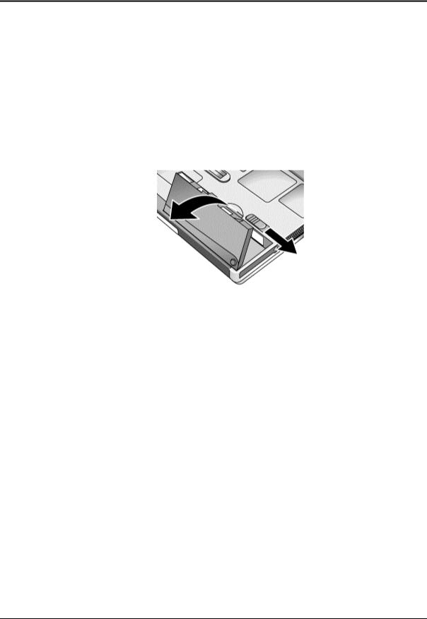
Removing the Main Battery
(User-Replaceable)
One or two plug-in modules can be inserted in the module bays in the expansion base. The computer itself has no module bays.
Required Equipment
• None.
Removal Procedure
• Slide the battery’s release latch, then lift the battery out of its compartment.
Figure 2-2. Removing the Main Battery
Reassembly Note
•Insert the front end of the battery into the battery compartment, then press the back end in until it clicks into place.
2-4 |
Removal and Replacement |
HP Omnibook 500 |
 Loading...