


User’s Guide
DSn/SONET
Operation
HP 37718A
OmniBER 718
ã Copyright Hewlett-
Packard Ltd.1998
All rights reserved. Reproduction, adaption, or translation without prior written permission is prohibited, except as allowed under the copyright laws.
HP Part No. 37718-90022
First edition, 09/98
Second Edition, 12/98
Printed in U.K.
Warranty
The information contained in this document is subject to change without notice.
Hewlett-Packard makes no warranty of any kind with regard to this material, including, but not limited to, the implied warranties or merchantability and fitness for a particular purpose.
Hewlett-Packard shall not be liable for errors contained herein or for incidental or consequential damages in connection with the furnishing, performance, or use of this material.
WARNING
Warning Symbols Used on the Product
!
The product is marked with this symbol when the user should refer to the instruction manual in order to protect the apparatus against damage.
The product is marked with this symbol to indicate that hazardous voltages are present
The product is marked with this symbol to indicate that a laser is fitted. The user should refer to the laser safety information in the Calibration Manual.
Hewlett-Packard Limited
Telecommunications Networks Test Division
South Queensferry
West Lothian, Scotland EH30 9TG

User’s Guide DSn/SONET Operation
HP 37718A
OmniBER 718

About This Book
This book tells you how to select the features that you want to use for your test.
The selections available are presented in the following groups:
•Transmit and receive interfaces
•Test features, for example, the addition of errors and alarms to the test signal
•Measurements including test timing
•Storing, logging and printing results with general printer information
•Using instrument and disk storage
•Using the “Other” features.
The selections available will depend on the options fitted to your instrument. The examples given in this book cover all options and therefore may include selections which are not available on your instrument.
iv

Contents
1 Setting the Interfaces
Setting DSn Transmit Interface 2
Setting SONET Transmit Interface 4
Setting Jitter Transmit Interface 7
Setting Wander Transmit Interface 9
Setting SONET THRU Mode 11
Using Smart Test 13
Setting DSn Receive Interface 15
Setting SONET Receive Interface 17
Setting Jitter Receive Interface 18
Setting Extended Jitter Receive Interface 19
Setting Wander Receive Interface 20
2 Selecting Test Features
Using Transmit Overhead Setup 22
Using Receive Overhead Monitor 24
Setting Overhead Trace Messages 26
Generating Overhead Sequences 27
Using Receive Overhead Capture 29
Adding Frequency Offset to SONET Signal 31 Adding Frequency Offset to the DSn Signal 33 Setting up Signaling Bits 34
Setting Transmit Structured Payload/Test Signal 37 Setting Receive Structured Payload/Test Signal 39 Setting Transmit N x 64 kb/s/N x 56 kb/s Structured Payload/Test Signal 40
Setting Receive N x 64 kb/s/N x 56 kb/s Structured Payload/Test Signal 42
v

Contents
Inserting an External DSn Payload/Test Signal 43 Dropping an External Payload/Test Signal 46 Adding Errors & Alarms at the SONET Interface 49
Adding Errors & Alarms to the DSn Interface/DSn Payload 50 Using FEAC Codes 51
Setting DSn Spare Bits 53 Adding Pointer Adjustments 54
Using Pointer Graph Test Function 61 Stressing Optical Clock Recovery Circuits 63
Generating Automatic Protection Switch Messages 64 Inserting & Dropping Data Communications Channel 65
3 Making Measurements
Using Overhead BER Test Function 68
Test Timing 69
Making SONET Analysis Measurements 70
Making DSn Analysis Measurements 71
Measuring Frequency 72
Measuring Optical Power 73
Measuring Round Trip Delay 74
Monitoring Signaling Bits 76
Measuring Service Disruption Time 77
Performing a SONET Tributary Scan 80
Performing an SONET Alarm Scan 82
Performing a DSn Alarm Scan 83
Measuring Jitter 84
Measuring Extended Jitter 86
Measuring Wander 87
Measuring Jitter Tolerance 89
vi

Contents
Measuring Jitter Transfer 92
4 Storing, Logging and Printing
Saving Graphics Results to Instrument Store 98 Recalling Stored Graph Results 99
Viewing the Bar Graph Display 101
Viewing the Graphics Error and Alarm Summaries 103 Logging Graph Displays 105
Logging Results 107 Logging on Demand 110
Logging Jitter Tolerance Results 112
Logging Jitter Transfer Results 114
Logging Results to Parallel (Centronics) Printer 116 Logging Results to HP-IB Printer 117
Logging Results to Internal Printer 118 Logging Results to RS-232-C Printer 119 Printing Results from Disk 120
Connecting an HP 850C DeskJet Printer to a Parallel Port 121 Changing Internal Printer Paper 122
Cleaning Internal Printer Print Head 125
5 Using Instrument and Disk Storage
Storing Configurations in Instrument Store 128 Titling Configuration in Instrument Store 129 Recalling Configurations from Instrument Store 130 Formatting a Disk 131
vii

Contents
Labeling a Disk 132
Managing Files and Directories on Disk 133 Saving Graphics Results to Disk 140 Saving Data Logging to Disk 142
Saving Configurations to Disk 143 Recalling Configuration from Disk 144 Recalling Graphics Results from Disk 145
Copying Configuration from Instrument Store to Disk 146 Copying Configuration from Disk to Instrument Store 148 Copying Graphics Results from Instrument Store to Disk 150
6 Selecting and Using "Other" Features
Coupling Transmit and Receive Settings 154
Setting Time & Date 155
Enabling Keyboard Lock 156
Enabling Beep on Received Error 157
Suspending Test on Signal Loss 158
Setting Error Threshold Indication 159
Setting Screen Brightness and Color 160
Dumping Display to Disk 161
Running Self Test 163
viii

Contents
7STS-1 SPE Background Patterns
8ETSI/ANSI Terminology
ETSI/ANSI Conversion and Equivalent Terms 170
ix

Contents
x
1
Setting the Interfaces
This chapter tells you how to set the instrument interfaces to match the network being tested.
Setting the Interfaces
|
Setting DSn Transmit Interface |
||
Description |
DSn transmit interface settings should match network equipment |
||
|
settings of Rate, Termination and Line Code and determine the Payload |
||
|
to be tested. |
||
TIP: |
To set the Transmitter and Receiver to the same interface settings |
||
|
choose OTHER |
SETTINGS CONTROL |
COUPLED . |
|
|
|
|
HOW TO: |
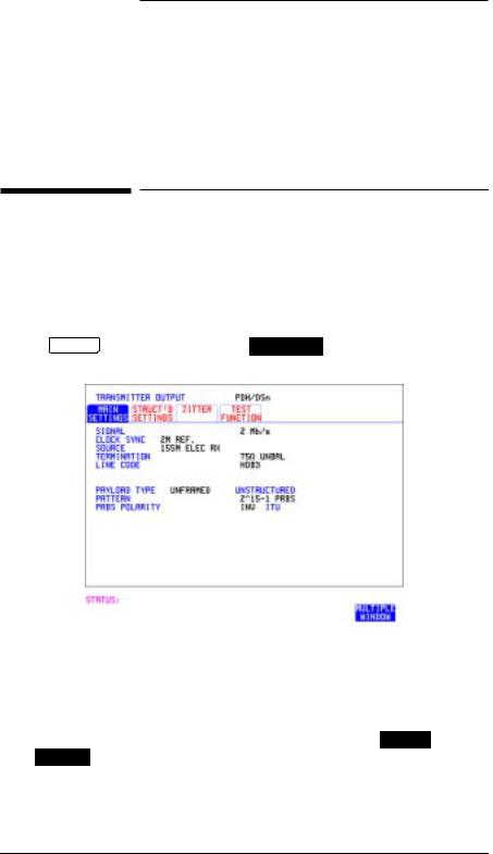
1 Choose the required SIGNAL rate. |
|
Rates of DS1, DS3, 2 Mb/s and 34 Mb/s are available. |
2If you have chosen 2 Mb/s as the SIGNAL rate, choose the required CLOCK SYNC source - internally generated or recovered from the received DSn signal.
If Jitter, Option 204, 205 or 206, is fitted and SIGNAL 2 Mb/s is chosen a 2M REF choice is added to the menu. This allows you to choose the
synchronization source for the 2 Mb/s reference. The synchronization source is supplied from the SONET Clock module. It can be internally generated, derived from an external clock or recovered from the SONET received signal.
2

Setting the Interfaces
Setting DSn Transmit Interface
3If DS1 or DS3 is chosen, choose the required OUTPUT LEVEL.
4If you have chosen 2 Mb/s as the SIGNAL rate, choose the required TERMINATION. (At all other signal rates the impedance is fixed).
5If you have chosen 2 Mb/s or DS1 as the SIGNAL rate, choose the required LINE CODE. (At 34 Mb/s and DS3 coding is fixed).
6If required, choose the FREQUENCY OFFSET value.
See “Adding Frequency Offset to the DSn Signal” page 33.
7 Choose the required PAYLOAD TYPE.
If |
STRUCTURED |
is required FRAMED must be chosen. |
If |
STRUCTURED |
is chosen the DSn test signal must be set up. See |
“Setting Transmit Structured Payload/Test Signal” page 37.
If you have chosen 2 Mb/s, DS1 or DS3 as the DSn signal rate, the Framed choice is expanded to provide a menu of framing types.
8 Choose the PATTERN type and the PRBS POLARITY.
3
Setting the Interfaces
Setting SONET Transmit Interface
Setting SONET Transmit Interface
Description SONET transmit interface settings should match the network equipment settings of Rate, Wavelength and Mapping, determine the payload to be tested and set background conditions to prevent alarms while testing.
TIP: If you wish to set the HP 37718A transmitter and receiver to the same interface settings choose OTHER SETTINGS CONTROL 
 COUPLED .
HOW TO: |
1 |
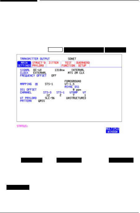
Make your choice of SIGNAL rate. |
|
|
If Option 106, Dual Wavelength optical module, is fitted and an optical |
|
|
rate is chosen, choose the required wavelength (1550) or (1310). |
|
|
If STS-1 is chosen, choose the required interface level. |
|
|
Choose INTERNAL unless THRU MODE is required. If THRU MODE is |
|
|
chosen, see "Setting SONET THRU Mode " page 11. |
|
2 |
Make your choice of CLOCK synchronization source. The RECEIVE |
|
|
clock synchronization choice depends on the SONET Receive Interface |
|
|
choice. |
|
|
EXTERNAL allows a choice of MTS, BITS or 10 MHz clocks. |
|
3 |
If required choose the FREQUENCY OFFSET value. See “Adding |
|
|
Frequency Offset to SONET Signal” page 31. |
4

Setting the Interfaces
Setting SONET Transmit Interface
4Choose FOREGROUND F/G MAPPING , BACKGROUND B/G MAPPING MAPPING and type of payload.
Mapping may be selected from a pictorial display by moving the cursor to MAPPING and pressing SET .
Use  and
and  to move between STS Layer choice, VT Layer choice and Payload Layer choice. Use
  and
and  to choose the mapping.
Use SET to confirm your choice and return to the SONET MAIN SETTINGS display.
5If VT-6 mapping is chosen, VT CONCATENATION selection is enabled, choose OFF or the tributary at which the concatenation begins, VT6-2C through VT6-6C.
The BACKGROUND, PATTERN IN OTHER VT-6’s is fixed at NUMBERED, that is, each VT-6 contains a unique number to allow identification in case of routing problems.
6If required, choose DS1/2M/34M/DS3 OFFSET value. See “Adding Frequency Offset to SONET Signal” page 31
7If FULL SPE, VT-6, VT-2 or VT-1.5 mapping is chosen, choose the test tributary CHANNEL, including the STS-3 for an OC-12/OC-48 signal.
8Choose the payload framing under PAYLOAD TYPE or VT PAYLOAD.
If |
STRUCTURED is required FRAMED must be chosen. |
If |
STRUCTURED is chosen, the Payload test signal must be set up. See |
“Setting Transmit Structured Payload/Test Signal” page 37. |
|
If |
INSERT is chosen, see “Inserting an External DSn Payload/Test |
Signal” page 43.
5
Setting the Interfaces
Setting SONET Transmit Interface
If you have chosen 2 Mb/s, DS1 or DS3 under Mapping, the Framed choice is expanded to provide a menu of framing types.
9 Choose the PATTERN type and PRBS polarity.
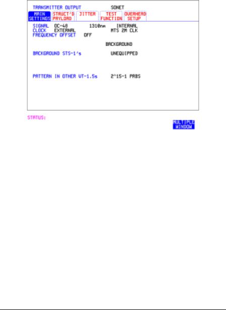
10Choose the mapping required in the background (non-test) STS’s.
11If VT mapping is chosen for the test STS, choose the PATTERN IN OTHER VT’s.
6
Setting the Interfaces
Setting Jitter Transmit Interface
Setting Jitter Transmit Interface
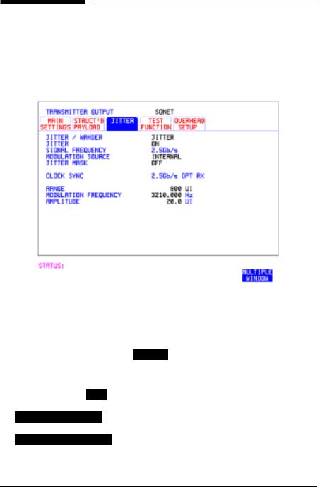
Description: You can add jitter to the transmitted DSn or SONET signal at 2 Mb/s, 34 Mb/s, STS-3, OC-3, OC-12, and OC-48. You can source the jitter modulation internally or from an external source.
HOW TO: |
1 If you are adding jitter to the DSn signal, set up the DSn transmit |
|
interface. See Chapter “Setting DSn Transmit Interface”. |
2If you are adding jitter to the SONET signal, set up the SONET transmit interface. See “Setting SONET Transmit Interface” page 4.
3Choose JITTER/WANDER JITTER .
If you wish to add wander to the DSn or SONET signal, See “Setting Wander Transmit Interface” page 9.
4Choose JITTER ON .
If you wish to perform a Jitter Tolerance measurement, choose AUTO TOLERANCE . See “Measuring Jitter Tolerance” page 89. If you wish to perform a Jitter Transfer measurement choose
TRANSFER FUNCTION . See “Measuring Jitter Transfer” page 92.
7

Setting the Interfaces
Setting Jitter Transmit Interface
5Choose the modulation source.
If adding jitter to the DSn signal and EXTERNAL is chosen, connect the external source to the MOD IN port of the DSn Jitter TX module. Up to 10 UI of external jitter modulation can be added at the MOD IN port.
If adding jitter to the SDH signal and EXTERNAL is chosen, connect the external source to the MOD IN port of the SONET Clock module. Up to 20 UI of external jitter modulation can be added at the MOD IN port.
6Choose the JITTER MASK setting required.
You can choose the jitter range, jitter modulating frequency and jitter amplitude if OFF is chosen.
If you choose SWEPT , the HP 37718A will "sweep" through the ITU-T jitter mask (G.823 for DSn, G.958, G.825 or G.253 for SONET) adjusting the jitter amplitude according to the jitter frequency.
If you choose SPOT , you can choose the "spot" jitter frequency. The jitter amplitude is adjusted and controlled according to your jitter frequency choice.
TIP: If, when using the SWEPT MASK capability, a problem occurs around a certain frequency, this may require closer examination. Stop the sweep at that point by choosing SPOT . You can then control the "spot" jitter
frequency to make closer examination of the problem.
8
Setting the Interfaces
Setting Wander Transmit Interface
Setting Wander Transmit Interface
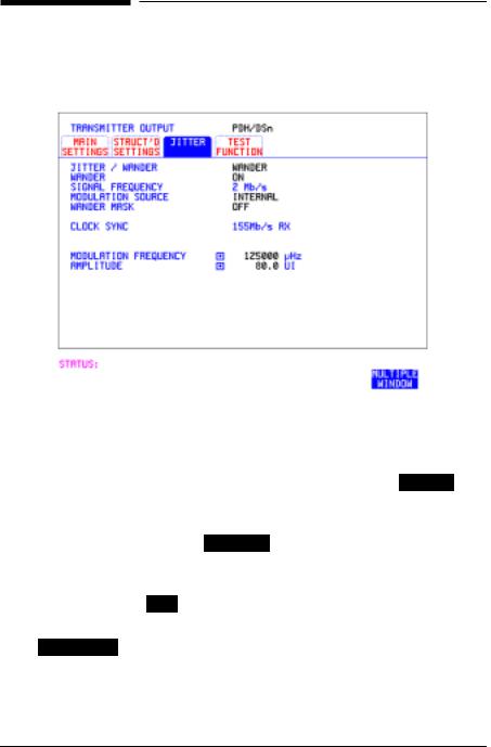
Description: You can add Wander to the 2 Mb/s DSn signal and the STS-3, OC-3, OC-12 or OC-48 SONET signal.
HOW TO: DSn Wander (2 Mb/s)
1Connect REF OUT on the SONET Clock module to REF IN on the DSn Jitter TX module (this provides the Wander Reference).
2Set up the DSn transmit interface, choose CLOCK SYNC 2M REF and select the SOURCE required from the menu. See “Setting DSn Transmit Interface” page 2.
3Choose JITTER/WANDER WANDER .
If you wish to add jitter to the DSn signal, See “Setting Jitter Transmit Interface” page 7.
4Choose WANDER ON .
5Choose the modulation source.
If EXTERNAL is chosen, connect the external source to the MOD IN port of the DSn Jitter TX module. Up to 10 UI of external wander modulation can be added.
9

Setting the Interfaces
Setting Wander Transmit Interface
6Choose the WANDER MASK setting required.
You can choose the wander modulating frequency and wander amplitude if OFF is chosen.
If you choose SPOT , you can choose the "spot" wander frequency. The wander amplitude is adjusted and controlled according to your wander frequency choice.
SONET Wander (STS-3, OC-3, OC-12, OC-48)
7Set up the SONET transmit interface. See “Setting SONET Transmit Interface” page 4.
8Choose JITTER/WANDER WANDER .
If you wish to add jitter to the SONET signal, see "Setting Jitter Transmit Interface " page 7.
9Choose WANDER ON .
10Choose the WANDER MASK setting required.
You can choose the wander modulating frequency and wander amplitude if OFF is chosen.
If you choose SPOT , you can choose the "spot" wander frequency. The wander amplitude is adjusted and controlled according to your wander frequency choice.
10
Setting the Interfaces
Setting SONET THRU Mode
Setting SONET THRU Mode
Description THRU mode is used to non-intrusively monitor SONET lines where no protected monitor points are available.
As THRU mode locks some user settings, you must set SIGNAL RATE, STS rate, STS-1 SPE CHANNEL (if appropriate) before selecting THRU mode.
The entire frame can be errorred at a user defined rate if PAYLOAD
OVERWRITE and TOH+POH CHANNEL OVERWRITE are both set to OFF . If either overwrite is enabled the ENTIRE FRAME ERROR RATE
function is disabled.
OC-1/STS-1, OC-3/STS-3
You can substitute a new payload, Section and Line Overhead (TOH) and Path overhead (POH) in the received OC-1/STS-1 or OC-3/STS-3 signal for testing.
OC-12, OC-48
The overhead and payload may be overwritten for STS-3c SPE and AU3. PAYLOAD OVERWRITE is not available for STS-12C or STS-48C. TOH+POH CHANNEL overwrite is available for STS-12C and STS-48C.
HOW TO: |
1 Make the required SIGNAL RATE, MAPPING and CHANNEL |
|
choices on the SONET TRANSMIT and RECEIVE displays, See |
|
"Setting SONET Transmit Interface " page 4 and "Setting SONET |
|
Receive Interface " page 17. |
11

Setting the Interfaces
Setting SONET THRU Mode
2Make the PAYLOAD OVERWRITE choice required.
If STS-3c SPE, STS-1 SPE, VT-6, VT-2 or VT-1.5 is chosen, the Section, Line and Path CVs are recalculated before transmission and the Mapping, Selected VT, VT Payload, Pattern, Tributary Offset and Pattern in other VT’s settings are displayed. To choose the settings in these, See "Setting SONET Transmit Interface " page 4, steps 4 through 10.
3Make the TOH+POH CHANNEL OVERWRITE choice required.
You can only modify those overhead bytes available under TRANSMIT SONET 
 TEST FUNCTION
 SONET : Errors & Alarms, Sequences, Overhead BER, APS Messages and DCC Insert.
The Section, Line and Path CVs are recalculated before transmission.
4If you wish to add jitter to the STS-3, OC-3, OC-12 or OC-48 signal, See “Setting Jitter Transmit Interface” page 7.
12
Setting the Interfaces
Using Smart Test
|
Using Smart Test |
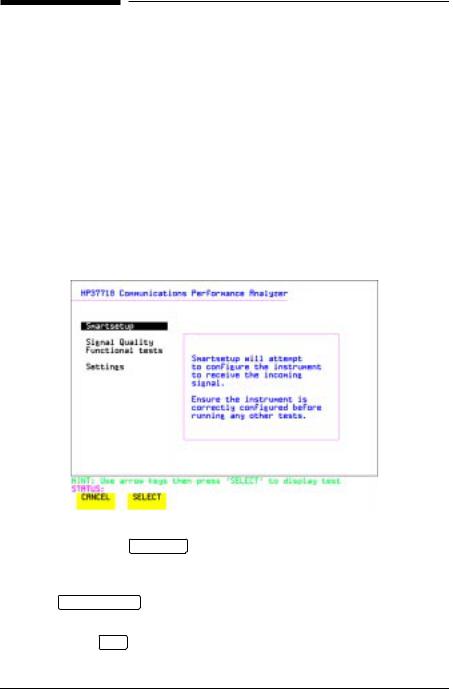
Description |
The Smart Test function can help speed-up configuring the instrument in |
|
two ways. |
|
1 A Smartsetup feature that will attempt to configure the instrument |
|
to receive the incoming signal. |
|
2 A series of “links” that provide quick access to some of the most |
|
frequently used features of the instrument. Note that these tests are |
|
run with the instrument in its current configuration, no attempt is |
|
made to set the instrument to the requirements of the test. |
|
Smartsetup can help the user by attempting to identify the incoming |
|
signal structure and detect mixed payload signal structures. |
HOW TO USE |
1 |
Connect the HP 37718A to the network and choose if necessary the |
||
SMARTSETUP: |
|
required SONET RECEIVE interface on the HP 37718A (Smartsetup |
||
|
|
will select DSn or SONET/SDH, but can not select between SONET |
||
|
|
and SDH). |
||
|
2 |
Press SMART TEST . |
||
|
|
The display will show the Smart Test menu above. |
||
|
3 |
Press either SET or |
|
. |
|
SELECT |
|||
|
|
|
|
|
13
Setting the Interfaces
Using Smart Test
4In SONET mode the incoming signal will be identified on the top line of the display, and under this the payload mappings, the J1 Trace and C2 byte indicators are displayed on the bottom lines.
5Use the  and
and  keys to display the J1 Trace information for each STS SPE. When the STS SPE of interest has been identified choose
either |
VIEW PAYLOAD |
or |
PRBS SEARCH . |
|
|
||
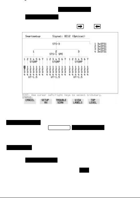
6 Choosing VIEW PAYLOAD |
will identify and display the payload |
||||||
mapping of the TUG structured signal, as shown below. |
|||||||
Choose the required tributary using |
|
and |
|
. |
|||
|
|
||||||
|
|
||||||
|
|||||||
7 There are four choices available at this point:
 which sets the receiver to receive the selected tributary.
TROUBLE SCAN which sets the receiver to receive the selected tributary, exits to the RESULTS TROUBLE SCAN display and starts gating.

 which displays the C2/V5/J1/J2 trace information for the selected tributary.
TOP LEVEL which returns the display to the STS SPE selection window.
8 Choosing PRBS SEARCH at Step 5 will prompt you for additional information about patterns and which mapping to search. When the required data has been entered press GO .
9When the search is complete a tributary display appears, with any
tributaries containing the required PRBS indicated with a “P”. Choose the required tributary using  and
and  .
.
14
Setting the Interfaces
Setting DSn Receive Interface
|
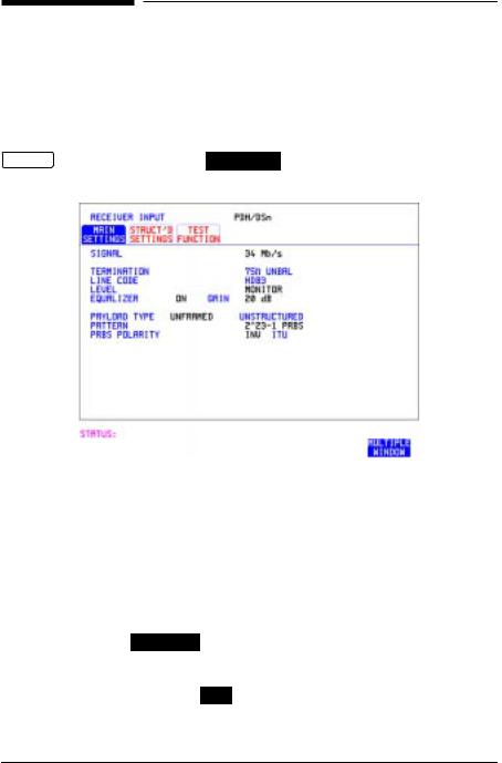
Setting DSn Receive Interface |
||
Description |
DSn Receive interface settings should match the network equipment |
||
|
settings of Rate, Termination and Line Code and determine the Payload |
||
|
to be tested. |
||
TIP: |
To set the transmitter and receiver to the same interface settings choose |
||
|
OTHER |
SETTINGS CONTROL |
COUPLED . |
|
|
|
|
HOW TO: |
1 Choose the required SIGNAL rate. |
2If you have chosen 2 Mb/s as the SIGNAL rate, choose the required TERMINATION. (At all other rates the impedance is fixed.)
3If you have chosen 2 Mb/s or DS1 as the SIGNAL rate, choose the required LINE CODE. (At 34Mb/s and DS3 coding is fixed.)
4If you are measuring at the network equipment monitor point, set the
LEVEL field to MONITOR . In this case the received signal will be 20 to 30 dB below the normal level.
Choose the GAIN required to return the received signal to normal. Choose EQUALIZATION ON to compensate for cable losses if required.
15

Setting the Interfaces
Setting DSn Receive Interface
5 Choose the PAYLOAD TYPE.
If |
STRUCTURED |
is required FRAMED must be chosen. |
If |
STRUCTURED |
is chosen, the DSn test signal must be set up. See |
“Setting Transmit Structured Payload/Test Signal” page 37.
If you chose 2 Mb/s, DS1 or DS3 as the PDH/DSn SIGNAL rate, the FRAMED choice is expanded to provide a menu of framing types.
6 Choose the PATTERN type and the PRBS POLARITY required.
16
Setting the Interfaces
Setting SONET Receive Interface
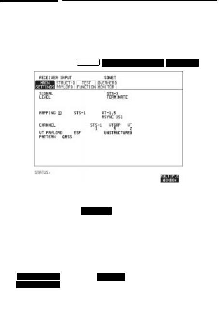
Setting SONET Receive Interface
Description SONET Receive interface settings should match the network equipment settings of Rate and Mapping, and determine the payload to be tested.
TIP: If you wish to set the HP 37718A transmitter and receiver to the same interface settings, choose OTHER SETTINGS CONTROL 
 COUPLED .
HOW TO: |
1 Choose the required SIGNAL source. |
|
If STS-1 or STS-3 is chosen, choose the required LEVEL. |
|
If the LEVEL chosen is MONITOR choose the required GAIN. |
2Choose mapping and type of payload.
3If VT-6 mapping is chosen, and CONCATENATION is enabled, choose the tributary at which the concatenation begins.
If VT-6, VT-2 or VT-1.5 mapping is chosen, choose the test tributary under CHANNEL.
4Choose the payload framing under PAYLOAD TYPE or VT PAYLOAD.
If |
STRUCTURED is required FRAMED must be chosen. |
If |
STRUCTURED is chosen the Payload test signal must be set up. See |
“Setting Receive Structured Payload/Test Signal” page 39.
If DROP is chosen, see “Dropping an External Payload/Test Signal” page 46.
5 Choose the PATTERN type and PRBS polarity.
17
Setting the Interfaces
Setting Jitter Receive Interface
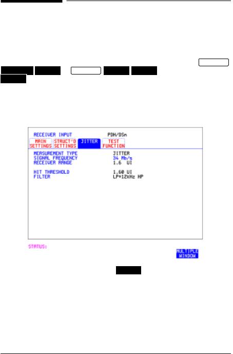
Setting Jitter Receive Interface
Description: Jitter and error measurements are made simultaneously when a jitter option is fitted. The measurements are made on the normal input to the DSn or SONET receiver and the interface selections are the normal Receiver selections. The jitter receive interface is selected with RECEIVE PDH/DSn JITTER or RECEIVE SONET JITTER MEASUREMENT TYPE
JITTER . |
The choices made on the jitter receive interface determine the jitter measurement range, the threshold level for determining a jitter hit and which filters are used in the jitter measurement.
HOW TO: 1 Choose MEASUREMENT TYPE JITTER .
2Choose the RECEIVER RANGE - the jitter measurement range.
3Choose the HIT THRESHOLD level - if the received jitter exceeds the value chosen a jitter hit is recorded.
4Choose the FILTER you wish to include in the peak to peak and RMS jitter measurement.
18
Setting the Interfaces
Setting Extended Jitter Receive Interface
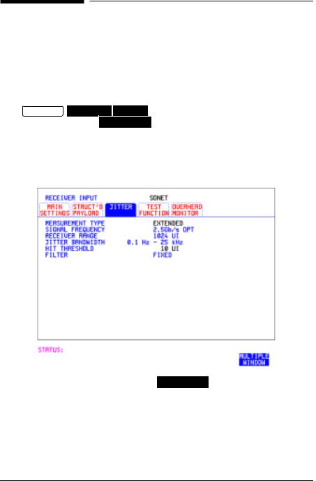
Setting Extended Jitter Receive
Interface
Description: Extended Jitter measurements are made in a jitter bandwidth of 0.1 Hz to 25 kHz. These measurements are made at the upper end of the standard wander frequency range and the lower end of the standard jitter frequency range. The extended jitter receive interface is selected
with RECEIVE PDH/DSn 
 JITTER or


MEASUREMENT TYPE EXTENDED .
The choices made on the jitter receive interface determine the threshold level for determining a jitter hit. The measurement Range and the Filters are not selectable.
HOW TO: 1 Choose MEASUREMENT TYPE EXTENDED .
2Choose the HIT THRESHOLD level - if the received jitter exceeds the value chosen a jitter hit is recorded.
19
Setting the Interfaces
Setting Wander Receive Interface
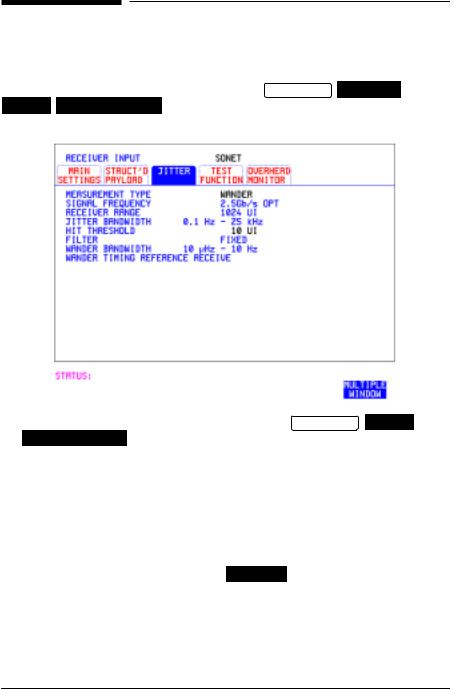
Setting Wander Receive Interface
Description: You can measure Wander at all DSn and SONET rates. An external timing reference should be selected on the TRANSMIT PDH/DSn or
SONET |
MAIN SETTINGS display to ensure accurate Wander results. |
HOW TO: |
1 |
Choose an external timing reference on the TRANSMIT |
SONET |
|
|
MAIN SETTINGS display. See, “Setting SONET Transmit Interface” |
|
|
|
page 4. |
|
2If you intend to measure wander on a DSn signal, set up the DSn receive interface. See, “Setting DSn Receive Interface” page 15.
3If you intend to measure wander on a SONET signal, set up the SONET receive interface. See, “Setting SONET Receive Interface” page 17.
4Choose MEASUREMENT TYPE WANDER .
5Choose the wander HIT THRESHOLD - if the received wander exceeds the value chosen a wander hit is recorded.
20
 Loading...