


 Loading...
HP LaserJet M1005 MFP
Service Manual

HP LaserJet M1005 MFP
Service Manual

Copyright and License
© 2006 Copyright Hewlett-Packard
Development Company, L.P.
Reproduction, adaptation, or translation without prior written permission is prohibited, except as allowed under the copyright laws.
The information contained in this document is subject to change without notice.
The only warranties for HP products and services are set forth in the express warranty statements accompanying such products and services. Nothing herein should be construed as constituting an additional warranty. HP shall not be liable for technical or editorial errors or omissions contained herein.
Part number CB376-90929
Edition 1, 8/2006
Trademark credits
Microsoft®, Windows®, and Windows NT® are U.S. registered trademarks of Microsoft Corporation.
Linux is a U.S. registered trademark of Linus Torvalds.
PostScript® is a trademarks of Adobe Systems Incorporated.
UNIX® is a registered trademark of The Open Group.
Energy Star® and the Energy Star® logo are U.S. registered marks of the United States Environmental Protection Agency.
Table of contents
1 Device information |
|
Quick access to device information ...................................................................................................... |
2 |
Model and serial number label ............................................................................................................. |
3 |
Features at a glance ............................................................................................................................. |
4 |
Walkaround .......................................................................................................................................... |
5 |
General guidelines ............................................................................................................................... |
6 |
Choosing paper and other media ......................................................................................................... |
6 |
HP media ............................................................................................................................. |
6 |
Media to avoid ..................................................................................................................... |
6 |
Media that can damage the device ...................................................................................... |
7 |
Guidelines for using media ................................................................................................................... |
8 |
Paper ................................................................................................................................... |
8 |
Colored paper ...................................................................................................................... |
9 |
Custom-size media .............................................................................................................. |
9 |
Labels .................................................................................................................................. |
9 |
Label construction ............................................................................................... |
9 |
Transparencies .................................................................................................................... |
9 |
Envelopes .......................................................................................................................... |
10 |
Envelope construction ....................................................................................... |
10 |
Envelopes with double-side seams ................................................................... |
10 |
Envelopes with adhesive strips or flaps ............................................................ |
11 |
Envelope storage .............................................................................................. |
11 |
Card stock and heavy media ............................................................................................. |
11 |
Card stock construction ..................................................................................... |
11 |
Card stock guidelines ........................................................................................ |
11 |
Letterhead and preprinted forms ....................................................................................... |
12 |
Supported media weights and sizes ................................................................................................... |
13 |
Printing and storage environment ...................................................................................................... |
14 |
2 Installation |
|
What is in the box ............................................................................................................................... |
16 |
Site requirements ............................................................................................................................... |
17 |
Physical specifications ....................................................................................................... |
17 |
Space requirements ........................................................................................................... |
17 |
Loading media .................................................................................................................................... |
18 |
Loading documents to copy or scan .................................................................................. |
18 |
Loading input trays ............................................................................................................ |
18 |
Main input tray (tray 1) ...................................................................................... |
18 |
Priority input tray ............................................................................................... |
19 |
ENWW |
iii |
Connect power ................................................................................................................................... |
20 |
Minimum system requirements .......................................................................................................... |
21 |
Supported operating systems ............................................................................................................. |
21 |
Software installation ........................................................................................................................... |
22 |
Printer driver ....................................................................................................................................... |
23 |
Printer-driver Help .............................................................................................................. |
23 |
Changing printer-driver settings ......................................................................................... |
24 |
Software for Windows ........................................................................................................................ |
25 |
HP LaserJet Scan software ............................................................................................... |
25 |
Installing Windows device software ................................................................................... |
25 |
Uninstalling Windows device software ............................................................................... |
25 |
Uninstalling Macintosh device software ............................................................................. |
25 |
3 Managing the device |
|
Control panel ...................................................................................................................................... |
28 |
Information pages ............................................................................................................................... |
29 |
Managing supplies ............................................................................................................................. |
30 |
Checking supplies status ................................................................................................... |
30 |
Storing supplies ................................................................................................................. |
30 |
Replacing and recycling supplies ...................................................................................... |
30 |
HP policy on non-HP supplies ........................................................................................... |
30 |
HP fraud hotline ................................................................................................................. |
31 |
Supplies .............................................................................................................................................. |
32 |
Cable and interface accessories ........................................................................................................ |
32 |
User-replaceable parts ....................................................................................................................... |
32 |
Paper and other print media ............................................................................................................... |
32 |
4 Maintenance |
|
Cleaning the device ............................................................................................................................ |
36 |
To clean the exterior .......................................................................................................... |
36 |
To clean the scanner glass ................................................................................................ |
36 |
To clean the lid backing ..................................................................................................... |
36 |
To clean the paper path ..................................................................................................... |
37 |
Print cartridge ..................................................................................................................................... |
38 |
Approximate print-cartridge replacement intervals ............................................................ |
38 |
Managing the print cartridge .............................................................................................. |
38 |
Print-cartridge life expectancy ........................................................................... |
38 |
Print-cartridge storage ....................................................................................... |
38 |
HP policy on non-HP print cartridges ................................................................ |
38 |
HP fraud hotline ................................................................................................ |
38 |
Replacing supplies and parts ............................................................................................................. |
40 |
Supply replacement guidelines .......................................................................................... |
40 |
Changing the print cartridge .............................................................................................. |
40 |
5 Theory of Operation |
|
Basic functions ................................................................................................................................... |
44 |
Basic sequence of operation .............................................................................................................. |
45 |
Formatter system ............................................................................................................................... |
46 |
Central processing unit ...................................................................................................... |
46 |
iv |
ENWW |
Standard boot process ....................................................................................................... |
46 |
Device startup messages .................................................................................. |
46 |
RAM ................................................................................................................................... |
47 |
Universal serial bus (USB) interface .................................................................................. |
47 |
Control panel ..................................................................................................................... |
47 |
EconoMode ........................................................................................................................ |
47 |
Device functions ................................................................................................................................. |
48 |
Engine control system (engine control unit and power-supply assembly) ......................... |
48 |
Device engine control system ........................................................................... |
49 |
Device laser/scanner unit ................................................................................. |
49 |
Power system on the power-supply assembly .................................................. |
49 |
Image-formation system .................................................................................................... |
51 |
The seven image-formation processes ............................................................ |
52 |
Print cartridge .................................................................................................................... |
53 |
Device paper-feed system ................................................................................................. |
53 |
Jam detection in the device ............................................................................................... |
54 |
Conditions of jam detection ............................................................................... |
54 |
HP LaserJet M1005 MFP unique components ................................................................................... |
56 |
Scanner functions and operation ....................................................................................... |
56 |
Scanner functions ............................................................................................ |
56 |
Scanner operation ............................................................................................. |
57 |
6 Removal and replacement |
|
Removal and replacement strategy .................................................................................................... |
60 |
Admonitions ....................................................................................................................... |
60 |
Required tools .................................................................................................................... |
60 |
Before performing service .................................................................................................. |
61 |
After performing service ..................................................................................................... |
61 |
Parts removal order ........................................................................................................... |
61 |
Flatbed lid .......................................................................................................................... |
63 |
Control-panel overlay ......................................................................................................... |
64 |
Control panel ..................................................................................................................... |
65 |
Scanner assembly ............................................................................................................. |
67 |
Device separation pad ....................................................................................................... |
73 |
Print cartridge .................................................................................................................... |
74 |
Device pickup roller ........................................................................................................... |
75 |
Media input tray ................................................................................................................. |
78 |
Transfer roller .................................................................................................................... |
80 |
Device side covers ............................................................................................................. |
82 |
Print-cartridge door ............................................................................................................ |
85 |
Rear cover and fuser cover ............................................................................................... |
86 |
Front cover ......................................................................................................................... |
88 |
Installing the scanner cushions .......................................................................................... |
90 |
Power supply ..................................................................................................................... |
91 |
Formatter ........................................................................................................................... |
94 |
Scanner support frame ..................................................................................................... |
95 |
Engine controller unit ......................................................................................................... |
98 |
Laser/scanner assembly .................................................................................................. |
102 |
Main motor ....................................................................................................................... |
103 |
Fuser ................................................................................................................................ |
105 |
ENWW |
v |
Paper-pickup assembly ................................................................................................... |
107 |
7 Troubleshooting |
|
Basic troubleshooting ....................................................................................................................... |
110 |
Control-panel messages .................................................................................................................. |
113 |
Alert and warning messages .......................................................................................... |
113 |
Critical error messages ................................................................................................... |
113 |
Event-log codes ............................................................................................................... |
115 |
Solving image-quality problems ....................................................................................................... |
116 |
Checking the print cartridge ............................................................................................ |
116 |
To redistribute the toner in the print cartridge ................................................. |
116 |
Solving print image-quality problems ............................................................................... |
116 |
Print image-quality problems ........................................................................... |
116 |
Solving scanning (copying) image-quality problems ........................................................................ |
124 |
Scanning (copying) image-quality problems .................................................................... |
124 |
Repetitive image defect ruler ............................................................................................................ |
130 |
Solving paper-feed problems ........................................................................................................... |
131 |
Jams occur in the device ................................................................................................. |
131 |
To clear a jam ................................................................................................. |
131 |
Solving print paper-feed problems ................................................................................... |
132 |
Print paper-feed problems ............................................................................... |
133 |
Functional checks ............................................................................................................................. |
135 |
Half self-test functional check ......................................................................................... |
135 |
To perform a half self-test check ..................................................................... |
135 |
To perform other checks ................................................................................. |
135 |
Drum rotation functional check ........................................................................................ |
136 |
High-voltage contacts check ............................................................................................ |
137 |
To check the print-cartridge contacts .............................................................. |
137 |
To check the high-voltage connector pins ....................................................... |
138 |
Firmware update using a flash executable file ................................................................................. |
139 |
Troubleshooting tools ....................................................................................................................... |
140 |
Printing a configuration report, demonstration page, or menu structure .......................... |
140 |
Service-mode functions .................................................................................................................... |
141 |
Secondary service menu ................................................................................................. |
141 |
To gain access to the secondary service menu .............................................. |
141 |
Adjusting the country/region code parameters ................................................................ |
142 |
To change the country/region from one location to another ............................ |
142 |
To set the language and location if none is set ............................................... |
142 |
NVRAM init ...................................................................................................................... |
142 |
To perform NVRAM init ................................................................................... |
143 |
System settings for localized products ............................................................................ |
143 |
Main wiring ....................................................................................................................................... |
146 |
Component locations ........................................................................................................................ |
148 |
8 Parts and diagrams |
|
Ordering parts and supplies ............................................................................................................. |
152 |
Parts that wear ................................................................................................................ |
152 |
Parts ................................................................................................................................ |
152 |
World-wide customer support .......................................................................................... |
152 |
Accessories ...................................................................................................................................... |
153 |
vi |
ENWW |
Common hardware .......................................................................................................... |
153 |
How to use the parts lists and diagrams .......................................................................... |
154 |
Scanner assembly ............................................................................................................................ |
156 |
Formatter .......................................................................................................................................... |
158 |
Whole unit replacement part ............................................................................................................ |
160 |
Alphabetical parts list ....................................................................................................................... |
176 |
Numerical parts list ........................................................................................................................... |
180 |
Appendix A Device specifications |
|
Physical specifications ..................................................................................................................... |
186 |
Electrical specifications .................................................................................................................... |
186 |
Power consumption .......................................................................................................................... |
186 |
Environmental specifications ............................................................................................................ |
186 |
Acoustic emissions ........................................................................................................................... |
187 |
Appendix B Product warranty |
|
Hewlett-Packard Limited Warranty Statement ................................................................................. |
190 |
Availability of support and service .................................................................................................... |
191 |
HP maintenance agreements ........................................................................................................... |
192 |
Next-Day Onsite Service ................................................................................................. |
192 |
Appendix C Regulatory information |
|
FCC compliance ............................................................................................................................... |
194 |
Declaration of conformity ................................................................................................................. |
195 |
Country-/region-specific safety statements ...................................................................................... |
196 |
Laser safety statement .................................................................................................... |
196 |
Canadian DOC statement ................................................................................................ |
196 |
Korean EMI statement ..................................................................................................... |
196 |
Finnish laser statement .................................................................................................... |
197 |
Index ................................................................................................................................................................. |
199 |
ENWW |
vii |
viii |
ENWW |
List of tables
Table 1-1 |
Device guides ..................................................................................................................................... |
2 |
Table 1-2 |
Features ............................................................................................................................................. |
4 |
Table 1-3 |
Priority input tray specifications ........................................................................................................ |
13 |
Table 1-4 |
Tray 1 specifications ........................................................................................................................ |
13 |
Table 2-1 |
Physical dimensions for the HP LaserJet M1005 MFP .................................................................... |
17 |
Table 5-1 |
HP LaserJet M1005 MFP ................................................................................................................. |
45 |
Table 5-2 |
Device startup messages ................................................................................................................. |
46 |
Table 5-3 |
Dc power distribution ........................................................................................................................ |
49 |
Table 7-1 |
Event-log codes ............................................................................................................................. |
115 |
Table 7-2 |
System settings .............................................................................................................................. |
143 |
Table 8-1 |
Technical support websites and related documentation ................................................................ |
152 |
Table 8-2 |
Accessories .................................................................................................................................... |
153 |
Table 8-3 |
Common fasteners ........................................................................................................................ |
153 |
Table 8-4 |
Scanner assembly .......................................................................................................................... |
157 |
Table 8-5 |
Formatter ........................................................................................................................................ |
159 |
Table 8-6 |
Whole unit replacement part .......................................................................................................... |
161 |
Table 8-7 |
Pickupand deliverytray assemblies ............................................................................................ |
163 |
Table 8-8 |
External covers .............................................................................................................................. |
165 |
Table 8-9 |
Internal components (1 of 3) .......................................................................................................... |
167 |
Table 8-10 |
Internal components (2 of 3) ........................................................................................................ |
169 |
Table 8-11 |
Internal components (3 of 3) ........................................................................................................ |
171 |
Table 8-12 |
Paper-pickup assembly ................................................................................................................ |
173 |
Table 8-13 |
Fuser (fixing assy) assembly ........................................................................................................ |
175 |
Table 8-14 |
Alphabetical parts list ................................................................................................................... |
176 |
Table 8-15 |
Numerical parts list ....................................................................................................................... |
180 |
Table A-1 |
Physical specifications ................................................................................................................... |
186 |
Table A-2 |
Electrical specifications .................................................................................................................. |
186 |
Table A-3 |
Power consumption (average, in watts), ...................................................................................... 186 |
|
Table A-4 |
Environmental specifications ........................................................................................................ |
186 |
Table A-5 |
Acoustic emissions , ...................................................................................................................... 187 |
|
ENWW |
ix |
x |
ENWW |
List of figures
Figure 1-1 Model and serial number label .......................................................................................................... |
3 |
|
Figure 1-2 |
Front view ......................................................................................................................................... |
5 |
Figure 1-3 |
Back view .......................................................................................................................................... |
5 |
Figure 2-1 What is in the shipping box ............................................................................................................. |
16 |
|
Figure 2-2 |
Space requirements ........................................................................................................................ |
17 |
Figure 2-3 Loading documents to copy or scan ............................................................................................... |
18 |
|
Figure 2-4 Loading the main input tray (tray 1) (1 of 2) .................................................................................... |
18 |
|
Figure 2-5 Loading the main input tray (tray 1) (2 of 2) .................................................................................... |
19 |
|
Figure 2-6 Loading the priority input tray (1 of 2) ............................................................................................. |
19 |
|
Figure 2-7 Loading the priority input tray (2 of 2) ............................................................................................. |
19 |
|
Figure 2-8 |
Connect power ................................................................................................................................ |
20 |
Figure 3-1 |
Control panel ................................................................................................................................... |
28 |
Figure 4-1 Cleaning the scanner glass ............................................................................................................ |
36 |
|
Figure 4-2 Cleaning the lid backing .................................................................................................................. |
37 |
|
Figure 4-3 Changing the print cartridge (1 of 5) ............................................................................................... |
40 |
|
Figure 4-4 Changing the print cartridge (2 of 5) ............................................................................................... |
40 |
|
Figure 4-5 Changing the print cartridge (3 of 5) ............................................................................................... |
41 |
|
Figure 4-6 Changing the print cartridge (4 of 5) ............................................................................................... |
41 |
|
Figure 4-7 Changing the print cartridge (5 of 5) ............................................................................................... |
41 |
|
Figure 5-1 |
Device configuration ....................................................................................................................... |
44 |
Figure 5-2 Device functional block diagram ..................................................................................................... |
48 |
|
Figure 5-3 High-voltage power supply circuit ................................................................................................... |
51 |
|
Figure 5-4 Image-formation block diagram ..................................................................................................... |
52 |
|
Figure 5-5 Device paper path .......................................................................................................................... |
54 |
|
Figure 5-6 HP LaserJet M1005 MFP optical system (1 of 2) ........................................................................... |
56 |
|
Figure 5-7 HP LaserJet M1005 MFP optical system (2 of 2) ........................................................................... |
57 |
|
Figure 6-1 Parts removal order for the HP LaserJet M1005 MFP .................................................................... |
62 |
|
Figure 6-2 Remove the flatbed lid (1 of 2) ........................................................................................................ |
63 |
|
Figure 6-3 Remove the control-panel overlay .................................................................................................. |
64 |
|
Figure 6-4 Remove the control panel (1 of 4) .................................................................................................. |
65 |
|
Figure 6-5 Remove the control panel (2 of 4) .................................................................................................. |
65 |
|
Figure 6-6 Remove the control panel (3 of 4) .................................................................................................. |
66 |
|
Figure 6-7 Remove the control panel (4 of 4) .................................................................................................. |
66 |
|
Figure 6-8 Remove the scanner assembly (1 of 11) ........................................................................................ |
67 |
|
Figure 6-9 Remove the scanner assembly (2 of 11) ........................................................................................ |
67 |
|
Figure 6-10 Remove the scanner assembly (3 of 11) ...................................................................................... |
68 |
|
Figure 6-11 Remove the scanner assembly (4 of 11) ...................................................................................... |
68 |
|
Figure 6-12 Remove the scanner assembly (5 of 11) ...................................................................................... |
69 |
|
Figure 6-13 Remove the scanner assembly (6 of 11) ...................................................................................... |
69 |
|
Figure 6-14 Remove the scanner assembly (7 of 11) ...................................................................................... |
70 |
|
ENWW |
xi |
Figure 6-15 Remove the scanner assembly (8 of 11) ...................................................................................... |
70 |
Figure 6-16 Remove the scanner assembly (9 of 11) ...................................................................................... |
71 |
Figure 6-17 Remove the scanner assembly (10 of 11) .................................................................................... |
71 |
Figure 6-18 Remove the scanner assembly (11 of 11) .................................................................................... |
72 |
Figure 6-19 Remove the device separation pad (1 of 2) .................................................................................. |
73 |
Figure 6-20 Remove the device separation pad (2 of 2) .................................................................................. |
73 |
Figure 6-21 Remove the print cartridge (1 of 2) ............................................................................................... |
74 |
Figure 6-22 Remove the print cartridge (2 of 2) ............................................................................................... |
74 |
Figure 6-23 Remove the device pickup roller (1 of 5) ...................................................................................... |
75 |
Figure 6-24 Remove the device pickup roller (2 of 5) ...................................................................................... |
75 |
Figure 6-25 Remove the device pickup roller (3 of 5) ...................................................................................... |
76 |
Figure 6-26 Remove the device pickup roller (4 of 5) ...................................................................................... |
76 |
Figure 6-27 Remove the device pickup roller (5 of 5) ...................................................................................... |
77 |
Figure 6-28 Remove the media input tray (1 of 3) ........................................................................................... |
78 |
Figure 6-29 Remove the media input tray (2 of 3) ........................................................................................... |
78 |
Figure 6-30 Remove the media input tray (3 of 3) ........................................................................................... |
79 |
Figure 6-31 Remove the transfer roller (1 of 3) ................................................................................................ |
80 |
Figure 6-32 Remove the transfer roller (2 of 3) ................................................................................................ |
81 |
Figure 6-33 Remove the transfer roller (3 of 3) ................................................................................................ |
81 |
Figure 6-34 Remove the device side covers (1 of 3) ....................................................................................... |
82 |
Figure 6-35 Remove the device side covers (2 of 3) ...................................................................................... |
83 |
Figure 6-36 Remove the device side covers (2 of 3) ...................................................................................... |
83 |
Figure 6-37 Remove the device side covers (3 of 3) ....................................................................................... |
84 |
Figure 6-38 Remove the print-cartridge door (1 of 2) ....................................................................................... |
85 |
Figure 6-39 Remove the print-cartridge door (2 of 2) ....................................................................................... |
85 |
Figure 6-40 Remove the rear cover and fuser cover (1 of 3) ........................................................................... |
86 |
Figure 6-41 Remove the rear cover and fuser cover (2 of 3) ........................................................................... |
86 |
Figure 6-42 Remove the rear cover and fuser cover (3 of 3) ........................................................................... |
87 |
Figure 6-43 Remove the front cover (1 of 3) .................................................................................................... |
88 |
Figure 6-44 Remove the front cover (2 of 3) .................................................................................................... |
88 |
Figure 6-45 Remove the front cover (3 of 3) .................................................................................................... |
89 |
Figure 6-46 Reinstalling the front cover ........................................................................................................... |
89 |
Figure 6-47 Installing the scanner cushions ..................................................................................................... |
90 |
Figure 6-48 Remove the power supply (1 of 3) ................................................................................................ |
91 |
Figure 6-49 Remove the power supply (2 of 3) ................................................................................................ |
92 |
Figure 6-50 Remove the power supply (3 of 3) ................................................................................................ |
92 |
Figure 6-51 Remove the formatter (1 of 2) ....................................................................................................... |
94 |
Figure 6-52 Remove the formatter (2 of 2) ....................................................................................................... |
94 |
Figure 6-53 Remove the scanner support frame (1 of 3) ................................................................................. |
95 |
Figure 6-54 Remove the scanner support frame (2 of 3) ................................................................................. |
96 |
Figure 6-55 Remove the scanner support frame (3 of 3) ................................................................................. |
96 |
Figure 6-56 Remove the ECU (1 of 6) .............................................................................................................. |
98 |
Figure 6-57 Remove the ECU (2 of 6) .............................................................................................................. |
99 |
Figure 6-58 Remove the ECU (3 of 6) .............................................................................................................. |
99 |
Figure 6-59 Remove the ECU (4 of 6) ............................................................................................................ |
100 |
Figure 6-60 Remove the ECU (5 of 6) ............................................................................................................ |
100 |
Figure 6-61 Remove the ECU (6 of 6) ............................................................................................................ |
101 |
Figure 6-62 Remove the laser/scanner assembly .......................................................................................... |
102 |
Figure 6-63 Remove the main motor (1 of 2) ................................................................................................. |
103 |
Figure 6-64 Remove the main motor (2 of 2) ................................................................................................. |
104 |
xii |
ENWW |
Figure 6-65 Remove the fuser assembly (1 of 2) ........................................................................................... |
105 |
|
Figure 6-66 Remove the fuser assembly (2 of 2) ........................................................................................... |
106 |
|
Figure 6-67 Fragile tab on fuser assembly ..................................................................................................... |
106 |
|
Figure 6-68 Remove the paper-pickup assembly .......................................................................................... |
107 |
|
Figure 7-1 Repetitive image defect ruler ........................................................................................................ |
130 |
|
Figure 7-2 Clear a jam in the device base (1 of 3) ......................................................................................... |
131 |
|
Figure 7-3 Clear a jam in the device base (2 of 3) ......................................................................................... |
132 |
|
Figure 7-4 Clear a jam in the device base (3 of 3) ......................................................................................... |
132 |
|
Figure 7-5 Check the fuser connectors on the fuser ...................................................................................... |
136 |
|
Figure 7-6 Check the fuser connectors on the power supply ......................................................................... |
136 |
|
Figure 7-7 Print-cartridge high-voltage contacts ............................................................................................ |
137 |
|
Figure 7-8 |
High-voltage contacts ................................................................................................................... |
138 |
Figure 7-9 Main wiring, HP LaserJet M1005 MFP scanner assembly ........................................................... |
146 |
|
Figure 7-10 Main wiring, HP LaserJet M1005 MFP device base ................................................................... |
147 |
|
Figure 7-11 HP LaserJet M1005 MFP component locations (1 of 2) ............................................................. |
148 |
|
Figure 7-12 HP LaserJet M1005 MFP component locations (2 of 2) ............................................................. |
149 |
|
Figure 8-1 |
Scanner assembly ........................................................................................................................ |
156 |
Figure 8-2 |
Formatter ...................................................................................................................................... |
158 |
Figure 8-3 Whole unit replacement part ......................................................................................................... |
160 |
|
Figure 8-4 Pickupand delivery-tray assemblies ........................................................................................... |
162 |
|
Figure 8-5 |
External covers ............................................................................................................................. |
164 |
Figure 8-6 Internal components (1 of 3) ......................................................................................................... |
166 |
|
Figure 8-7 Internal components (2 of 3) ......................................................................................................... |
168 |
|
Figure 8-8 Internal components (3 of 3) ......................................................................................................... |
170 |
|
Figure 8-9 |
Paper-pickup assembly ................................................................................................................. |
172 |
Figure 8-10 Fuser (fixing assy) assembly ...................................................................................................... |
174 |
|
ENWW |
xiii |
xiv |
ENWW |
1 Device information
●Quick access to device information
●Model and serial number label
●Features at a glance
●Walkaround
●General guidelines
●Choosing paper and other media
●Guidelines for using media
●Supported media weights and sizes
●Printing and storage environment
ENWW |
1 |

Quick access to device information
Several references are available for use with this device.
●HP LaserJet M1005 MFP: www.hp.com/support/LJm_1005.
Table 1-1 Device guides
Guide |
Description |
|
|
Getting started guide |
Provides step-by-step instructions for installing and setting up the device. |
|
|
User guide |
Provides detailed information for using and troubleshooting the device. Available on the |
|
device CD. |
|
|
Online Help |
Provides information about options that are available in the device drivers. To view a Help |
|
file, open the online Help through the printer driver. |
|
|
2 Chapter 1 Device information |
ENWW |

Model and serial number label
The model and serial number are located on a label found on the back of the device.
Figure 1-1 Model and serial number label
ENWW |
Model and serial number label 3 |

Features at a glance
Table 1-2 Features
Feature |
Description |
|
|
● Prints letter-size pages at speeds up to 15 pages per minute (ppm) and A4-size pages |
|
|
at speeds up to 14 ppm |
|
● Prints at 600 dots per inch (dpi) and FastRes 1200 dpi |
|
● Includes adjustable settings to optimize print quality |
|
● Average yield for the standard black print cartridge is 2,000 pages in accordance with |
|
ISO/IEC 19752. Actual yield depends on specific use. |
|
|
Copy |
● Copies at 600 dots per inch (dpi) |
|
|
Memory |
● Includes 32-megabyte (MB) random-access memory (RAM) |
|
|
Paper handling |
● Priority input tray holds up to 10 pages |
|
● Tray 1 holds up to 150 sheets of print media or 10 envelopes |
|
● Output bin holds up to 100 sheets of print media |
|
|
Scan |
● Provides 1200 pixels per inch (ppi) full-color scanning |
|
|
Printer driver |
● FastRes 1200 produces 1200-dots-per-inch (dpi) print quality for fast, high-quality |
|
printing of business text and graphics |
|
|
Interface connections |
● Includes a Hi-Speed USB 2.0 port |
|
|
Environmental features |
● ENERGY STAR®-qualified |
|
|
Economical printing |
● Provides N-up printing (printing more than one page on a sheet) |
|
● Provides an EconoMode setting, which uses less toner |
|
|
Supplies |
● Uses a print cartridge that has a no-shake design |
|
|
Accessibility |
● Online user guide is compatible with text screen-readers |
|
● Print cartridge can be installed and removed by using one hand |
|
● All doors and covers can be opened by using one hand |
|
|
4 Chapter 1 Device information |
ENWW |
Walkaround
1
2
3
4
6 5
Figure 1-2 Front view
1Flatbed scanner cover
2Control panel
3Cartridge-door release
4Output bin
5Priority input tray
6Tray 1
7 |
8 |
|
9 |
||
|
||
Figure 1-3 |
Back view |
7Hi-Speed USB 2.0 port
8Power switch
9Power receptacle
ENWW |
Walkaround |
5 |

General guidelines
Some media might meet all of the guidelines in this manual and still not produce satisfactory results. This problem might be the result of improper handling, unacceptable temperature and humidity levels, or other variables over which Hewlett-Packard has no control.
Before purchasing large quantities of print media, always test a sample and make sure that the print media meets the requirements specified in this service manual and in the HP LaserJet Printer Family Print Media Guide, which you can view on the Web at www.hp.com/support/ljpaperguide.
CAUTION Using media that does not meet HP specifications can cause problems for the device, requiring repair. This repair is not covered by the Hewlett-Packard warranty or service agreements.
The device accepts a variety of media, such as cut-sheet paper (including up to 100% recycled-fiber- content paper), envelopes, labels, transparencies, LaserJet glossy paper, HP LaserJet Tough paper, and custom-size paper. Properties such as weight, composition, grain, and moisture content are important factors that affect performance and output quality. Media that does not meet the guidelines outlined in this manual can cause the following problems:
●Poor print quality
●Increased jams
●Premature wear on the device, requiring repair
Choosing paper and other media
Properties such as weight, grain, and moisture content are important factors that affect performance and quality. To achieve the best possible print quality, only use high-quality media that is designed for laser printers.
NOTE Always test a sample of the media before you purchase large quantities. Your media supplier should understand the requirements specified in the HP LaserJet Printer Family Print Media Guide (HP part number 5963-7863).
HP media
HP recommends that you use HP LaserJet media in the device.
Media to avoid
The device can handle many types of media. Using media that is outside the specifications degrades print quality and increases the chance of jams occurring. See Guidelines for using media
on page 8.
●Do not use media that is too rough.
●Do not use media that contains cutouts or perforations other than standard 3-hole punched paper.
●Do not use multipart forms.
●Do not use paper that contains a watermark if you are printing solid patterns.
6 Chapter 1 Device information |
ENWW |
Media that can damage the device
In rare circumstances media can damage the device. Avoid the following types of media to prevent possible damage:
●Do not use media with staples or paper clips attached.
●Do not use transparencies designed for inkjet printers or other low-temperature printers. Use only transparencies that are specified for use with HP LaserJet devices.
●Do not use photo paper intended for inkjet printers.
●Do not use paper that is embossed or coated and is not designed for the temperature of the imagefuser. Select media that can tolerate temperatures of 200°C (392°F) for 0.1 second.
HP manufactures a media that is designed for the device.
●Do not use letterhead paper that was produced with low-temperature dyes or thermography. Preprinted forms or letterhead must use inks that can tolerate temperatures of 200°C (392°F) for 0.1 second.
●Do not use any media that produces emissions, or that melts, offsets, or discolors when exposed to 200°C (392°F) for 0.1 second.
To order HP LaserJet printing supplies, go to www.hp.com/go/ljsupplies in the U.S. or to www.hp.com/ ghp/buyonline.html/ worldwide.
ENWW |
Choosing paper and other media 7 |

Guidelines for using media
The following sections provide guidelines and instructions for printing on transparencies, envelopes, and other special media. Guidelines and specifications are included to help you select media that optimizes print quality and avoid media that can cause jams or damage the device.
Paper
For best results, use conventional 80-g/m2 or 20-lb paper. Make sure that the paper is of good quality and free of cuts, nicks, tears, spots, loose particles, dust, wrinkles, voids, and curled or bent edges.
If you are unsure about what type of paper you are loading (such as bond or recycled), check the label on the package of paper.
Some paper causes print quality problems, jamming, or damage to the device.
Symptom |
Problem with paper |
Solution |
|
|
|
Poor print quality or toner adhesion |
Too moist, too rough, too smooth, or |
Problems with feeding |
embossed |
|
Try another kind of paper that has a smoothness rating of 100-250 Sheffield and has 4-6% moisture content.
Check the device and make sure that the appropriate media type has been selected.
Dropouts, jamming, or curl |
Stored improperly |
Store paper flat in its moisture-proof |
|
|
wrapping. |
|
|
|
Increased gray background shading |
Might be too heavy |
Use lighter paper. |
Excessive curl |
Too moist, wrong grain direction, or |
Problems with feeding |
short-grain construction |
|
Use long-grain paper.
Check the device and make sure that the appropriate media type has been selected.
Jamming or damage to device |
Cutouts or perforations |
Do not use paper with cutouts or |
|
|
perforations. |
|
|
|
Problems with feeding |
Ragged edges |
Use good quality paper. |
|
|
|
NOTE The device uses heat and pressure to fuse toner to the paper. Make sure that any colored paper or preprinted forms use inks that are compatible with the fuser temperature of 200°C (392° F) for 0.1 second.
Do not use letterhead that is printed with low-temperature inks, such as those used in some types of thermography.
Do not use raised letterhead.
Do not use transparencies that are designed for inkjet printers or other low-temperature printers. Use only transparencies that are specified for use with HP LaserJet printers.
CAUTION Failure to follow these guidelines could cause jams or damage to the device.
8 Chapter 1 Device information |
ENWW |

Colored paper
●Colored paper should be of the same high quality as white xerographic paper.
●Pigments used must be able to withstand the fuser temperature of 200°C (392°F) for 0.1 second without deterioration.
●Do not use paper with a colored coating that was added after the paper was produced.
Custom-size media
Use the main input tray for multiple sheets.
CAUTION Make sure that the sheets are not stuck together before you load them.
Labels
HP recommends that you print labels from the priority input tray.
CAUTION Do not feed a sheet of labels through the device more than once. The adhesive degrades and might damage the device.
Label construction
When selecting labels, consider the quality of the following components:
●Adhesives: The adhesive material should be stable at 200°C (392°F), the maximum fuser temperature.
●Arrangement: Only use labels with no exposed backing between them. Labels can peel off sheets that have spaces between the labels, causing serious jams.
●Curl: Before printing, labels must lie flat with no more than 13 mm (0.5 inch) of curl in any direction.
●Condition: Do not use labels with wrinkles, bubbles, or other indications of separation.
Transparencies
Transparencies must be able to withstand 200°C (392°F), the maximum fuser temperature.
CAUTION You can print transparencies from the 150-sheet tray (tray 1). However, do not load more than 75 transparencies at one time into the tray.
ENWW |
Guidelines for using media 9 |
Envelopes
HP recommends that you print envelopes from the priority input tray.
Envelope construction
Envelope construction is critical. Envelope fold lines can vary considerably, not only between manufacturers, but also within a box from the same manufacturer. Successful printing on envelopes depends upon the quality of the envelopes. When selecting envelopes, consider the following components:
●Weight: The weight of the envelope paper should not exceed 90 g/m2 (24 lb), or jamming might result.
●Construction: Before printing, envelopes should lie flat with less than 6 mm (0.25 inch) of curl, and should not contain air. Envelopes that trap air can cause problems. Do not use envelopes that contain clasps, snaps, tie strings, transparent windows, holes, perforations, cutouts, synthetic materials, stamping, or embossing. Do not use envelopes with adhesives that require pressure to seal them.
●Condition: Make sure that the envelopes are not wrinkled, nicked, or otherwise damaged. Make sure that the envelopes do not have any exposed adhesive.
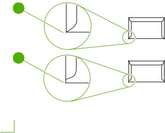
Envelopes with double-side seams
An envelope with double-side-seam construction has vertical seams at both ends of the envelope rather than diagonal seams. This style might be more likely to wrinkle. Make sure that the seam extends all the way to the corner of the envelope as shown in the following illustration:
1
2
1Acceptable envelope construction
2Unacceptable envelope construction
10 Chapter 1 Device information |
ENWW |

Envelopes with adhesive strips or flaps
Envelopes with a peel-off adhesive strip or with more than one flap that folds over to seal must use adhesives compatible with the heat and pressure in the device: 200°C (392°F). The extra flaps and strips might cause wrinkling, creasing, or jams.
Envelope storage
Proper storage of envelopes contributes to good print quality. You should store envelopes flat. If air is trapped in an envelope, creating an air bubble, the envelope might wrinkle during printing.
Card stock and heavy media
You can print many types of card stock from the input tray, including index cards and postcards. Some card stock performs better than others because its construction is better suited for feeding through a laser printer.
For optimum performance, do not use paper heavier than 157 g/m2 (42 lb). Paper that is too heavy might cause misfeeds, stacking problems, jams, poor toner fusing, poor print quality, or excessive mechanical wear.
NOTE You might be able to print on heavier paper if you do not fill the input tray to capacity and if you use paper with a smoothness rating of 100-180 Sheffield.
In either the software program or the printer driver, select Heavy (106 g/m2 to 163 g/m2; 28to 43-lb bond) or Cardstock (135 g/m2 to 216 g/m2; 50to 80-lb cover) as the media type, or print from a tray that is configured for heavy paper. Because this setting affects all print jobs, it is important to return the device back to its original settings after the job has printed.
Card stock construction
●Smoothness: 135-157 g/m2 (36-42 lb) card stock should have a smoothness rating of 100-180 Sheffield. 60-135 g/m2 (16-36 lb) card stock should have a smoothness rating of 100-250 Sheffield.
●Construction: Card stock should lie flat with less than 5 mm (0.2 inch) of curl.
●Condition: Make sure that the card stock is not wrinkled, nicked, or otherwise damaged.
Card stock guidelines
●Set margins at least 2 mm (0.08 inch) away from the edges.
●Use tray 1 for card stock (135 g/m2 to 216 g/m2; 50to 80-lb cover).
ENWW |
Guidelines for using media 11 |

Letterhead and preprinted forms
Letterhead is premium paper that often has a watermark, sometimes uses cotton fiber, and is available in a wide range of colors and finishes with matching envelopes. Preprinted forms can be made of a broad spectrum of paper types ranging from recycled to premium.
Many manufacturers now design these grades of paper with properties optimized for laser printing and advertise the paper as laser compatible or laser guaranteed. Some of the rougher surface finishes, such as cockle, laid, or linen, might require the special fuser modes that are available on some device models to achieve adequate toner adhesion.
NOTE Some page-to-page variation is normal when printing with laser printers. This variation cannot be observed when printing on plain paper. However, this variation is obvious when printing on preprinted forms because the lines and boxes are already placed on the page.
To avoid problems when using preprinted forms, embossed paper, and letterhead, observe the following guidelines:
●Avoid using low-temperature inks (the kind used with some types of thermography).
●Use preprinted forms and letterhead paper that have been printed by offset lithography or engraving.
●Use forms that have been created with heat-resistant inks that will not melt, vaporize, or release emissions when heated to 200°C (392°F) for 0.1 second. Typically, oxidation-set or oil-based inks meet this requirement.
●When the form is preprinted, be careful not to change the moisture content of the paper, and do not use materials that change the paper's electrical or handling properties. Seal the forms in moisture-proof wrap to prevent moisture changes during storage.
●Avoid processing preprinted forms that have a finish or coating.
●Avoid using heavily embossed or raised-letterhead papers.
●Avoid papers that have heavily textured surfaces.
●Avoid using offset powders or other materials that prevent printed forms from sticking together.
NOTE To print a single-page cover letter on letterhead, followed by a multiple-page document, feed the letterhead face up in the priority input tray, and load the standard paper in the main input tray (tray 1). The device automatically prints from the priority input tray first.
12 Chapter 1 Device information |
ENWW |

Supported media weights and sizes
For optimum results, use conventional 80 to 90 g/m2 (20 to 24 lb) photocopy paper. Verify that the paper is of good quality and is free of cuts, nicks, tears, spots, loose particles, dust, wrinkles, curls, and bent edges.
NOTE The device supports a wide range of standard and custom sizes of print media. The capacity of trays and bins can vary depending on media weight and thickness and on environmental conditions. Use only transparencies that are designed for use with HP LaserJet printers. Inkjet and monochrome transparencies are not supported for the device.
Table 1-3 Priority input tray specifications
Media |
Dimensions1 |
Weight |
Capacity2 |
|
Paper |
Minimum: 89 x 44 mm (3.5 x |
42 to 260 g/m2 (11 to 69 lb) |
Up to 10 sheets of 80 g/m2 or 20 lb |
|
|
1.75 inches) |
|
paper |
|
|
|
|
|
|
|
Maximum: 216 x 356 mm (8.5 x |
|
|
|
|
14 inches) |
|
|
|
|
|
|
|
|
HP Cover paper3 |
Same as the preceding listed |
203 g/m2 (75 lb cover) |
1 sheet |
|
|
minimum and maximum sizes |
|
|
|
Transparencies and opaque |
Thickness: 0.10 to 0.13 mm (3.9 |
1 transparency |
||
|
||||
film |
|
to 5.1 mils) |
|
|
|
|
|
|
|
Labels4 |
|
Thickness: up to 0.23 mm (up to |
1 sheet of labels |
|
|
|
9 mils) |
|
|
|
|
|
|
|
Envelopes |
|
Up to 90 g/m2 (16 to 24 lb) |
Up to 10 |
1The device supports a wide range of standard and custom sizes of print media. Check the printer driver for supported sizes.
2Capacity can vary depending on media weight and thickness, and environmental conditions.
3Hewlett-Packard does not guarantee results when printing with other types of heavy paper.
4Smoothness: 100 to 250 (Sheffield).
Table 1-4 Tray 1 specifications
Media |
Dimensions1 |
Weight |
Capacity2 |
|
Minimum size |
76 x 127 mm (3 x 5 inches) |
60 to 163 g/m2 (16 to 43 lb) |
150 sheets of 80 g/m2 (20 lb) |
|
|
|
|
|
paper |
Maximum size |
216 x 356 mm (8.5 x 14 inches) |
|
||
|
|
|||
|
|
|
|
|
Letter |
216 x 279 mm (8.5 x 11 inches) |
|
|
|
|
|
|
|
|
A4 |
|
210 x 297 mm (8.3 x 11.7 inches) |
|
|
|
|
|
|
|
Legal |
216 x 356 mm (8.5 x 14 inches) |
|
|
|
|
|
|
|
|
A5 |
|
148 x 210 mm (5.8 x 8.3 inches) |
|
|
|
|
|
|
|
B5 |
(ISO) |
176 x 250 mm (6.9 x 9.9 inches) |
|
|
|
|
|
|
|
B5 |
(JIS) |
182 x 257 mm (7.2 x 10 inches) |
|
|
|
|
|
|
|
Executive |
191 x 267 mm (7.3 x 10.5 inches) |
|
|
|
|
|
|
|
|
8.5 x 13 inches |
216 x 330 mm (8.5 x 13 inches) |
|
|
|
1The device supports a wide range of standard sizes of print media. Check the printer driver for supported sizes.
2Capacity can vary depending on the media weight and thickness, and environmental conditions.
ENWW |
Supported media weights and sizes 13 |
Printing and storage environment
Ideally, the printing and media-storage environment should be at or near room temperature, and not too dry or too humid. Remember that paper absorbs and loses moisture rapidly.
Heat works with humidity to damage paper. Heat causes the moisture in paper to evaporate, while cold causes it to condense on the sheets. Heating systems and air conditioners remove most of the humidity from a room. As paper is opened and used, it loses moisture, causing streaks and smudging. Humid weather or water coolers can cause the humidity to increase in a room. As paper is opened and used it absorbs any excess moisture, causing light print and dropouts. Also, as paper loses and gains moisture it can distort. This issue can cause jams.
As a result, paper storage and handling are as important as the paper-making process itself. Paper storage environmental conditions directly affect the feed operation and print quality.
Care should be taken not to purchase more paper than can be easily used in a short time (about three months). Paper stored for long periods can experience heat and moisture extremes, which can cause damage. Planning is important to prevent damage to a large supply of paper.
Unopened paper in sealed reams can remain stable for several months before use. Opened packages of paper have more potential for environmental damage, especially if they are not wrapped with a moisture-proof barrier.
The media-storage environment should be maintained to ensure optimum performance. The required condition is 20° to 24°C (68° to 75°F), with a relative humidity of 45% to 55%. The following guidelines are helpful when evaluating the storage environment:
●Print media should be stored at or near room temperature.
●The air should not be too dry or too humid.
●The best way to store an opened ream of paper is to rewrap it tightly in its moisture-proof wrapping. If the device environment is subject to extremes, unwrap only the amount of paper to be used during the day's operation to prevent unwanted moisture changes.
●Avoid storing paper and print media near heating and air conditioning vents or near windows and doors that are frequently open.
14 Chapter 1 Device information |
ENWW |
Loading...