


 Loading...
Technical Reference
HP VISUALIZE J6000 Workstations
Manufacturing Part Number: HP Part No. A5990-90010
Edition E0600

Notice
The information contained in this document is subject to change without notice.
Restricted Rights Legend
Use, duplication, or disclosure by government is subject to restrictions as set forth in subdivision (c) (1) (ii) of the Rights in Technical Data and Computer Software Clause at DFARS 252.227.7013.
© Copyright 2000 Hewlett-Packard Company. All Rights Reserved.
This document contains proprietary information that is protected by copyright. All rights are reserved. No part of this document may be photocopied, reproduced or translated to another language without the prior written consent of Hewlett-Packard Company.
UNIX is a registered trademark in the United States and other countries, licensed exclusively through X/Open Company Limited.
©Copyright 1980, 1984 AT&T, Inc.
©Copyright 1979, 1980, 1983 The Regents of the University of California.
This software and documentation is based in part on the Fourth Berkeley Software Distribution under license from the Regents of the University of California.
2

Contents
1. LVD Product Information
Chapter Overview . . . . . . . . . . . . . . . . . . . . . . . . . . . . . . . . . . . . . . . . . . .12
Product Description . . . . . . . . . . . . . . . . . . . . . . . . . . . . . . . . . . . . . . . . . .12
Net Dimensions and Weights. . . . . . . . . . . . . . . . . . . . . . . . . . . . . . . . .12
Key Features. . . . . . . . . . . . . . . . . . . . . . . . . . . . . . . . . . . . . . . . . . . . . .14
Front Panel Components. . . . . . . . . . . . . . . . . . . . . . . . . . . . . . . . . . . . . .16 Power Switch . . . . . . . . . . . . . . . . . . . . . . . . . . . . . . . . . . . . . . . . . . . . .16 Thumbscrew on the Front Panel . . . . . . . . . . . . . . . . . . . . . . . . . . . . . .17 System LCD . . . . . . . . . . . . . . . . . . . . . . . . . . . . . . . . . . . . . . . . . . . . . .17 Internal Storage Devices . . . . . . . . . . . . . . . . . . . . . . . . . . . . . . . . . . . .18
Rear Panel Components . . . . . . . . . . . . . . . . . . . . . . . . . . . . . . . . . . . . . .25
Connectors on the Rear Panel . . . . . . . . . . . . . . . . . . . . . . . . . . . . . . . .26
Internal Components. . . . . . . . . . . . . . . . . . . . . . . . . . . . . . . . . . . . . . . . .29
Monitors . . . . . . . . . . . . . . . . . . . . . . . . . . . . . . . . . . . . . . . . . . . . . . . . . . .31
Keyboard . . . . . . . . . . . . . . . . . . . . . . . . . . . . . . . . . . . . . . . . . . . . . . . . . .31
Mouse . . . . . . . . . . . . . . . . . . . . . . . . . . . . . . . . . . . . . . . . . . . . . . . . . . . .31
Site Preparation and Installation. . . . . . . . . . . . . . . . . . . . . . . . . . . . . . .31
2. Troubleshooting
Chapter Overview . . . . . . . . . . . . . . . . . . . . . . . . . . . . . . . . . . . . . . . . . . .34
Introduction to Troubleshooting . . . . . . . . . . . . . . . . . . . . . . . . . . . . . . . .34
Flowcharts for Troubleshooting . . . . . . . . . . . . . . . . . . . . . . . . . . . . . . . .34
Dealing with a Boot Failure . . . . . . . . . . . . . . . . . . . . . . . . . . . . . . . . . . .39 Special Considerations . . . . . . . . . . . . . . . . . . . . . . . . . . . . . . . . . . . . . .39 Searching for Bootable Media . . . . . . . . . . . . . . . . . . . . . . . . . . . . . . . .40 Stable Storage. . . . . . . . . . . . . . . . . . . . . . . . . . . . . . . . . . . . . . . . . . . . .40 Boot Command Notations . . . . . . . . . . . . . . . . . . . . . . . . . . . . . . . . . . .40
3

Contents
Supported Boot Paths . . . . . . . . . . . . . . . . . . . . . . . . . . . . . . . . . . . . . . 41
Intermediate System Loader (ISL) Environment . . . . . . . . . . . . . . . . 41
Identifying LCD-Indicated Conditions . . . . . . . . . . . . . . . . . . . . . . . . . . 42
Selftest Failures . . . . . . . . . . . . . . . . . . . . . . . . . . . . . . . . . . . . . . . . . . 42
Memory Failures . . . . . . . . . . . . . . . . . . . . . . . . . . . . . . . . . . . . . . . . . . 43
Chassis Codes . . . . . . . . . . . . . . . . . . . . . . . . . . . . . . . . . . . . . . . . . . . . 44
Running System Verification Tests . . . . . . . . . . . . . . . . . . . . . . . . . . . . . 67
Running ODE-Based Diagnostics . . . . . . . . . . . . . . . . . . . . . . . . . . . . . . 68
Using the System Board LEDs for Troubleshooting . . . . . . . . . . . . . . . 69 Interpreting the LED Information. . . . . . . . . . . . . . . . . . . . . . . . . . . . 69 Troubleshooting with System Board LEDs . . . . . . . . . . . . . . . . . . . . . 71
3. System Upgrades
Chapter Overview . . . . . . . . . . . . . . . . . . . . . . . . . . . . . . . . . . . . . . . . . . 76
Workstation Configurations . . . . . . . . . . . . . . . . . . . . . . . . . . . . . . . . . 76
Tools Required . . . . . . . . . . . . . . . . . . . . . . . . . . . . . . . . . . . . . . . . . . . . . 77
System Upgrades . . . . . . . . . . . . . . . . . . . . . . . . . . . . . . . . . . . . . . . . . . . 78 Electrostatic Discharge (ESD) Precautions . . . . . . . . . . . . . . . . . . . . . 78 Prerequisite for the System Upgrade Procedures . . . . . . . . . . . . . . . . 79 Front Bezel and Top Cover . . . . . . . . . . . . . . . . . . . . . . . . . . . . . . . . . . 80 Installing and Removing the Hard Disk Drives . . . . . . . . . . . . . . . . . 82 Installing and Removing an Internal CD ROM Drive . . . . . . . . . . . . 83 Installing and Removing Memory DIMMs . . . . . . . . . . . . . . . . . . . . . 83 Installing and Removing an I/O Card . . . . . . . . . . . . . . . . . . . . . . . . . 85
4. Boot Console Handler
Chapter Overview . . . . . . . . . . . . . . . . . . . . . . . . . . . . . . . . . . . . . . . . . . 88
Boot Console Handler Features. . . . . . . . . . . . . . . . . . . . . . . . . . . . . . . . 89
4

Contents
Accessing the Boot Console Handler . . . . . . . . . . . . . . . . . . . . . . . . . . . .90
Boot Console Menus . . . . . . . . . . . . . . . . . . . . . . . . . . . . . . . . . . . . . . . . .91
Booting the Workstation . . . . . . . . . . . . . . . . . . . . . . . . . . . . . . . . . . . . . .95
Searching for Bootable Media . . . . . . . . . . . . . . . . . . . . . . . . . . . . . . . . . .97
Resetting the Workstation . . . . . . . . . . . . . . . . . . . . . . . . . . . . . . . . . . . .98
Displaying and Setting Paths . . . . . . . . . . . . . . . . . . . . . . . . . . . . . . . . . .99
Displaying and Setting the Monitor Type . . . . . . . . . . . . . . . . . . . . . . .101 The Monitor Command . . . . . . . . . . . . . . . . . . . . . . . . . . . . . . . . . . . .101 Displaying the Current Monitor Configuration . . . . . . . . . . . . . . . . .102 Setting the Monitor Type . . . . . . . . . . . . . . . . . . . . . . . . . . . . . . . . . . .102 Setting the Monitor Type at Power On . . . . . . . . . . . . . . . . . . . . . . . .104 Troubleshooting Monitor Problems . . . . . . . . . . . . . . . . . . . . . . . . . . .105 Changing the Console to an External Terminal . . . . . . . . . . . . . . . . .105
Displaying the Current Memory Configuration. . . . . . . . . . . . . . . . . . .106
Displaying the Status of the I/O Slots . . . . . . . . . . . . . . . . . . . . . . . . . .108
Setting the Auto Boot and Auto Search Flags . . . . . . . . . . . . . . . . . . . .109
Displaying and Setting the Security Mode. . . . . . . . . . . . . . . . . . . . . . .110
Displaying and Setting Fastboot Mode. . . . . . . . . . . . . . . . . . . . . . . . . .111
Displaying the LAN Station Address . . . . . . . . . . . . . . . . . . . . . . . . . . .112
Displaying System Information . . . . . . . . . . . . . . . . . . . . . . . . . . . . . . .113
Displaying PIM Information . . . . . . . . . . . . . . . . . . . . . . . . . . . . . . . . . .113
Using Remote Power-On . . . . . . . . . . . . . . . . . . . . . . . . . . . . . . . . . . . . .114
Troubleshooting Hint for an Unresponsive RPC . . . . . . . . . . . . . . . .115
Setting the Fan Speed . . . . . . . . . . . . . . . . . . . . . . . . . . . . . . . . . . . . . . .116
Rack-Mount Fan Speed . . . . . . . . . . . . . . . . . . . . . . . . . . . . . . . . . . . .116
Desk-Side Fan Speed . . . . . . . . . . . . . . . . . . . . . . . . . . . . . . . . . . . . . .116
5

Contents
Initial System Loader (ISL) Environment . . . . . . . . . . . . . . . . . . . . . . 118
Invoking ISL from the Boot Console Handler . . . . . . . . . . . . . . . . . . 118
ISL User Commands. . . . . . . . . . . . . . . . . . . . . . . . . . . . . . . . . . . . . . 119
5. Block Diagram
System Board and PCI Board . . . . . . . . . . . . . . . . . . . . . . . . . . . . . . . . 122
A. Regulatory Statements
Electromagnetic Compatibility . . . . . . . . . . . . . . . . . . . . . . . . . . . . . . . 125 Federal Communications Commission (FCC) . . . . . . . . . . . . . . . . . . 125 VCCI Statement for Class A Products . . . . . . . . . . . . . . . . . . . . . . . . 126 Korea RRL Statement for Class A Product . . . . . . . . . . . . . . . . . . . . 126 Taiwan Class A Warning . . . . . . . . . . . . . . . . . . . . . . . . . . . . . . . . . . 126
Optical and Acoustical Statements . . . . . . . . . . . . . . . . . . . . . . . . . . . . 127 Visible LED Statement . . . . . . . . . . . . . . . . . . . . . . . . . . . . . . . . . . . . 127 Laser Safety Statement for a Class 1 Laser Product . . . . . . . . . . . . 127 Regulation on Noise Declaration for Machines . . . . . . . . . . . . . . . . . 127
B. Specifications
Environmental Specifications . . . . . . . . . . . . . . . . . . . . . . . . . . . . . . . . 130
Altitude . . . . . . . . . . . . . . . . . . . . . . . . . . . . . . . . . . . . . . . . . . . . . . . . 130
DC Magnetic Field Interference. . . . . . . . . . . . . . . . . . . . . . . . . . . . . 130
Electromagnetic Interference (EMI) . . . . . . . . . . . . . . . . . . . . . . . . . 130
Electrostatic Discharge. . . . . . . . . . . . . . . . . . . . . . . . . . . . . . . . . . . . 130
Temperature . . . . . . . . . . . . . . . . . . . . . . . . . . . . . . . . . . . . . . . . . . . . 130
Humidity (Non-condensing) . . . . . . . . . . . . . . . . . . . . . . . . . . . . . . . . 130
Leakage Current . . . . . . . . . . . . . . . . . . . . . . . . . . . . . . . . . . . . . . . . . 130
Shock . . . . . . . . . . . . . . . . . . . . . . . . . . . . . . . . . . . . . . . . . . . . . . . . . . 131
Vibration . . . . . . . . . . . . . . . . . . . . . . . . . . . . . . . . . . . . . . . . . . . . . . . 131
Electrical Specifications . . . . . . . . . . . . . . . . . . . . . . . . . . . . . . . . . . . . . 132
6

Contents
Input Power . . . . . . . . . . . . . . . . . . . . . . . . . . . . . . . . . . . . . . . . . . . . .132
C. SCSI Connections
Appendix Overview . . . . . . . . . . . . . . . . . . . . . . . . . . . . . . . . . . . . . . . . .134
SCSI Bus Differences . . . . . . . . . . . . . . . . . . . . . . . . . . . . . . . . . . . . . . .135
SCSI Restrictions. . . . . . . . . . . . . . . . . . . . . . . . . . . . . . . . . . . . . . . . . . .136
Cables . . . . . . . . . . . . . . . . . . . . . . . . . . . . . . . . . . . . . . . . . . . . . . . . . .136
Terminators . . . . . . . . . . . . . . . . . . . . . . . . . . . . . . . . . . . . . . . . . . . . .136
SCSI Configuration Constraints . . . . . . . . . . . . . . . . . . . . . . . . . . . . .137
SCSI Bus Length Constraints. . . . . . . . . . . . . . . . . . . . . . . . . . . . . . . . .138
SE SCSI Bus Length . . . . . . . . . . . . . . . . . . . . . . . . . . . . . . . . . . . . . .138
LVD SCSI Bus Length . . . . . . . . . . . . . . . . . . . . . . . . . . . . . . . . . . . . .138
Assigning SCSI Device IDs . . . . . . . . . . . . . . . . . . . . . . . . . . . . . . . . . . .139
Assigning External SCSI Device IDs . . . . . . . . . . . . . . . . . . . . . . . . .140
Assigning Internal SCSI Device IDs . . . . . . . . . . . . . . . . . . . . . . . . . .140
D. Related Documentation
Additional Documentation . . . . . . . . . . . . . . . . . . . . . . . . . . . . . . . . . . .142
Site Preparation Guide . . . . . . . . . . . . . . . . . . . . . . . . . . . . . . . . . . . .142
Installation Poster and Getting Started Guide. . . . . . . . . . . . . . . . . .142
Parts and Replacement Guide . . . . . . . . . . . . . . . . . . . . . . . . . . . . . . .142
7

Contents
8

Preface
This Technical Reference provides instructions for installing and configuring hardware, system specifications and characteristics, instructions for using the Boot Console Handler, SCSI device information, error messages and troubleshooting hints for your HP VISUALIZE J6000 workstation.
Safety and Regulatory Statements
See Appendix A for the safety and regulatory statements that apply to the J6000 workstation.
Installation Notice
Products designated in the Hewlett-Packard price list as customer installable can be installed using the instructions provided with the product. If you have elected to have the product installed by our field personnel, you will be charged for this service as covered under the standard terms and conditions. For more information, please go to this web site:
www.hp.com/visualize/support
Related Manuals
For more information, refer to the following documents:
•Common Desktop Environment (CDE) User’s Guide
•Configuring HP-UX for Peripherals
•HP-UX System Administration Tasks
•HP CDE Getting Started Guide
•Managing Systems and Workgroups
•Using HP-UX.
•Using Your HP Workstation
•Getting Started Guide for the J6000
Note that the documents listed above can be viewed with a web browser using this URL:
http://www.docs.hp.com
9

Revision History
The revision history for each edition of the manual is listed below:
Edition |
Revision History |
E0600 |
First Printing |
Problems, Questions, and Suggestions
If you have any problems or questions with our hardware, software, or documentation, please contact either your HP Response Center or your local HP representative. If you have access to a web browser, you can get the latest software and hardware patches at the following URL:
http://www.hp.com/visualize/support/
Documentation Conventions
Unless otherwise noted in the text, this guide uses the following symbolic conventions.
Table 1. Documentation Conventions
user-supplied values |
Italic words or characters in syntax and command descriptions |
|
represent values that you must supply. Italics are also used in text |
|
for emphasis. |
screen display |
Information that the system displays, commands that you must use |
|
literally, and path names appear in this typeface. |
Enter |
Keycaps are presented with a special keycap font as shown in the left |
|
column. (In this document, we refer to the Enter key. On your |
|
keyboard, the key may be labeled either Enter or Return.) |
Electrostatic Discharge (ESD) Precautions
Electrostatic charges can damage the integrated circuits on printed circuit boards. To prevent such damage from occurring, observe the following precautions during board unpacking and installation:
•Work on a static-free mat.
•Wear a static strap to ensure that any accumulated electrostatic charge is discharged from your body to ground.
•Create a common ground for the equipment you are working on by connecting the static-free mat, static strap, and peripheral units to that piece of equipment.
•Keep uninstalled printed circuit boards in their protective antistatic bags.
•Handle printed circuit boards by their edges, once you have removed them from their protective antistatic bags.
10
1 LVD Product Information
This chapter provides general product information about the HP VISUALIZE J6000 workstation. This information is provided to help familiarize you with the main features and components of the workstation.
11

LVD Product Information
Chapter Overview
Chapter Overview
This chapter contains the following main sections:
•Product Description
•Front Panel Components
•Rear Panel Components
•Internal Components
•Monitors
•Keyboard and Mouse
Product Description
The HP VISUALIZE J6000 workstation is a high-performance system capable of handling the most complex problems in computational analysis, advanced 3-D design, and electronic circuit design and verification.
The J6000 has two PA-8600 microprocessors and sixteen memory slots on its system board. It has a 715 Watt power supply with no DC/DC converter units required.
Net Dimensions and Weights
The dimensions for the deskside system are listed below.
•Depth: 25.8 inches (65.5 cm)
•Width: 10.0 inches (25.4 cm)
•Height: 19.8 inches (53.3 cm)
The dimensions for the rack system are listed below.
•Depth: 24.5 inches (62.2 cm)
•Width: 16.7 inches (42.4 cm)
•Height: 3.4 inches (8.6 cm)
12 |
Chapter 1 |

LVD Product Information
Product Description
. Table 1-1 lists the net weights for the J6000.
Table 1-1. Net Weights for the J6000 Workstations
|
Weight |
|
|
Deskside Configuration |
Min. - 40lbs. (17 kg.) |
|
Max. - 49 lbs (22 kg.) |
|
|
Maximum Configuration (Rack |
Min. - 36lbs. (16 kg.) |
Mount)1 |
Max. - 41 ls. (18 kg.) |
Maximum Configuration (Twenty |
1200 pounds (544 kg) |
Fully Equipped Workstations and |
|
the Rack) |
|
|
|
1.The rails weigh approximately 10 lbs. (4 kg.). This weight is not included in these figures.
NOTE For environmental and electrical requirements, see Appendix B.
Chapter 1 |
13 |

LVD Product Information
Product Description
Key Features
The J6000 workstations have the following key features.
•CPUs:
—Two 552MHz PA-8600 microprocessors, each with 0.5 MB instruction cache and 1.0 MB data cache.
•Operating System (Native HP-UX):
—32-bit support requires HP-UX version 10.20 plus the June 1999 Workstation ACE (Additional Core Enhancements)
—64-bit support requires HP-UX version 11.0 plus ACE 9911
•User Interface: HP CDE (Common Desktop Environment) graphical user interface
•Compatibility: Sourceand binary-code compatible with the B-, C-, and J-Class product families
•Main Memory: Using 512MB or 1 GB DIMMs
—Sixteen DIMM slots in pairs (from 1GB up to 16GB total)
•Power Supply:
—500 Watt (output power), 715 Watt (input power) with two VRM modules
•Remote Power-On
—Remote power-on feature that allows you to power up and shut down your workstation remotely through the RS232 port.
•Internal Storage Devices:
—Up to two Low-Voltage Differential (LVD) SCSI hard drives.
—One optional ATAPI Slim-line CD drive.
•Standard Networking: Ethernet IEEE 802.3 RJ45, Twisted Pair 10/100 Base T
•Standard I/O: Two GB/sec aggregate I/O bandwidth
—Two low-voltage differntial (LVD) SCSI buses. One dedicated to the two internal disk drives and one for the external devices (multi-mode).
—Two USB (Universal Serial Bus) connectors (keyboard and mouse)
—Two serial interface connectors (RS-232C)
—Audio connectors (line input, line output, headphone, and microphone)
14 |
Chapter 1 |

LVD Product Information
Product Description
•I/O Expansion Capabilities: 64-bit PCI (Peripheral Connect Interface) slots
—Three PCI-4X slots at 3.3V, 66MHz
•Optional Graphics Cards Currently Supported:
—HP VISUALIZE-fx10
—HP VISUALIZE-fxe
•Monitors Currently Supported:
—PC compatible monitors that support a minimum resolution of 1024×768 and a frequency of 75Hz
•Standard Keyboard: The USB connector provides an interface for the keyboard to the system. This keyboard provides the standard keys found on most PC keyboards.
•Mouse: The HP mouse (USB) has left, middle, and right buttons that function the same as most mice. For general information on the various cursor shapes associated with different areas of HP CDE while using a mouse, see the Using Your HP Workstation document.
Chapter 1 |
15 |
LVD Product Information
Front Panel Components
Front Panel Components
Before powering on your system, you should become familiar with the system unit controls.
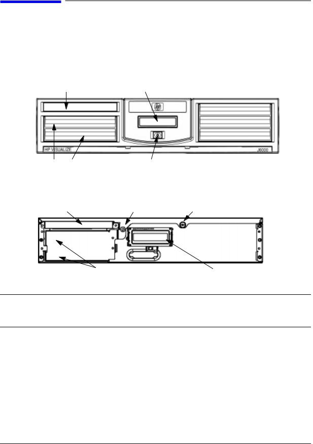
Figure 1-1 shows the front panel components with the bezel attached.
Figure 1-1. System Unit Front Panel Controls With Bezel
CD ROM Bay |
System LCD |
Hard Drive Bays |
Power Switch |
Figure 1-2. System Unit Front Panel Controls With Bezel Removed
CD Drive |
Locking Screw Captive Thumbscrew |
Hard Disk Drive Bay Areas |
System LCD |
CAUTION This workstation is designated for two-person lifting. It weighs approximately 36 to 49 pounds (16 to 22 kg), depending on the configuration. Do not attempt to lift it by yourself, or injury may result.
Power Switch
This switch turns the system on and off. When you turn your workstation off, the operating system automatically executes the shutdown -q command. This prevents any damage to programs and data on your system disk. Turning the power switch back on again automatically boots up the HP-UX operating system if your system has been configured to auto boot.
16 |
Chapter 1 |
LVD Product Information
Front Panel Components
Thumbscrew on the Front Panel
There is one captive thumbscrew near the center of the front panel. Loosening and pulling toward you with this screw allows the top panel to be removed. The top panel must be in place or the system will not power up.
Between the LCD panel and the CD ROM drive, there is a threaded hole for an optional locking screw. The locking screw is included in the bag of miscellaneous parts which comes with the workstation. This locking screw allows the user to protect his/her workstation form unwanted entry.
System LCD
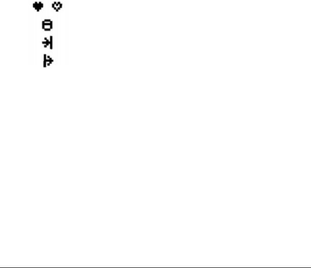
The Liquid Crystal Display (LCD) indicator is located on the front panel. The LCD has two 16 characters lines. The LCD displays messages about the state of the system, including chassis codes. The symbols in Figure 1-3 appear in the LCD if you have the HP-UX 10.20 or 11.0 operating system booted on your system. They represent the different system activities.
Figure 1-3. LCD Symbols
Operating system running (Heart Beat)
Disk access in progress
Network receive in progress
Network transmit in progress
Chapter 1 |
17 |

LVD Product Information
Front Panel Components
Internal Storage Devices
The J6000 workstations support the following internal storage devices, which are also located on the front panel, under the bezel:
•Up to two hot-pluggable, Low-Voltage Differential (LVD) hard disk drives
•One ATAPI (IDE) Slim-Line CD drive (optional)
The following subsections describe these internal storage devices.
Hard Disk Drive(s)
The J6000 workstations can support up to two hot-pluggable, Low-Voltage Differential (LVD) hard disk drives. These hard disk drives are 3.5-inch form factor, 10K RPM devices which connect to Ultra2 Wide LVD (Low Voltage Differential) SCSI interfaces on the disk bay backplane. The hard disk drive bays are located on the lower left side of the front panel, below the CD ROM drive. See Figure 1-1.
The two hard disk drive models currently supported are:
•18 GB LVD 10K RPM disk drive (Product Number A4998A)
•36 GB LVD 10K RPM disk drive (Product Number A6013A)
NOTE The ability to hot plug the hard disk drive(s) requires MirrorDisk/UX (Product Number B5403BA on HP-UX 10.20, or B2491BA on HP-UX 11.0 ACE 9911).
18 |
Chapter 1 |

LVD Product Information
Front Panel Components
The Hot-Plug Process
The physical aspect of inserting and removing a disk drive is discussed in the document that comes with the drive. However, the operating system must be prepared for the insertion or removal of a disk, or unexpected and harmful effects may occur.
There is a significant difference between the terms “hot-pluggable” and “hot-swappable”. Hot swapping happens at the device level; that is, a hot-swappable device manages insertion/removal on its own without assistance from HP-UX commands. The disk drive(s) in the J6000 are not hot-swappable; they are merely hot-pluggable. Thus, a manual software procedure must be done in order to safely remove or insert disk drives while the system is running.
The hot-plug process allows you to replace a defective disk drive in a high-available system while it is running.
Replacing a Failed Disk Drive
In the context of replacing a failed disk drive, the system administrator must determine which disk has failed. Depending on how the system was set up, the identity of the failed drive may or may not be obvious. This determination may be done in either of two ways:
•Tracking the error message written by the LVM (Logical Volume Manager) to the system console and/or a log file. For information on LVM commands, see the man pages for vgchange, lvreduce, vgfgrestore, lvlnboot, lvextend, lvsync, etc.
•If installed, run the diagnostic utility Support Tool Manager (xstm) to determine disk malfunction.
The removal of a defective disk drive from an active file system is supported through LVM commands if hot-pluggable disks have been configured into the HP-UX file system with LVM. To provide high availability, without impact to users, the disks must also be configured as mirrored disks. Disk-mirroring is accomplished through use of the MirrorDisk/UX software (HP part number B5403BA); for information on classes, see http://www.hgp.com/education/courses/h628s.html.
No graphical user interface is currently offered through the System Administrator Manager (SAM) for doing the required LVM commands because manipulation of the LVM requires specialized knowledge that only experienced system administrators are expected to have (see below for details).
Chapter 1 |
19 |

LVD Product Information
Front Panel Components
Hot-Plug Example
The following example describes a particular system problem where the solution is to replace a hot-plug disk module.
Volume group /dev/vg00 contains the two disks, with the logical volume configuration as shown:
Table 1-2. Example Configuration
Volume Description |
|
Volume Description |
|
|
|
|
|
|
|
Logical Volume 1 |
|
Logical Volume 3 |
|
|
|
|
|
|
|
Logical Volume 2 |
|
Logical Volume 4 |
|
|
|
|
|
|
|
Logical Volume 3 |
|
Logical Volume 5 |
|
|
|
|
|
|
|
hardware address |
10/0/12/0.0 |
10/0/13/0.0 |
||
device file (/dev/dsk/) c2t6d0 |
c2t5d0 |
|||
The system problem for this example is that the disk at hardware address 10/0/13/0.0 has a head crash, and as a result, is unusable. The steps described in the Hot-Plug Procedure section below outline a method that can be used to recover from this state.
1.All of the replaced disk’s in-use extents must belong to mirrored logical volumes which were created with the “strict” option (-s); see the documentation for MirrorDisk/UX.
2.You must have an up-to-date configuration backup file. This is done automatically each time an LVM command changes LVM configuration.
The default backup file’s path is:
/etc/lvmconf/<base_vg_name>.conf
For example,
/etc/lvmconf/vg00.conf
3. The replacement disk must be the same product ID as the replaced one.
NOTE HP often uses different manufacturers for disks having the same product number. The hot-plug manual procedure will not update the disk driver’s internal information to that of the replaced disk.
The replacement disk will have the same capacity and block size as the defective disk because they have the same product number. The only field that could be incorrect is the string specifying the vendor’s name. This will not affect the behavior of the LVM. If it is desired to update the manufacturer’s name, the disk’s volume group must be deactivated and reactivated. See the HP-UX System Administration Tasks manual for details.
20 |
Chapter 1 |
LVD Product Information
Front Panel Components
The Hot-Plug Procedure
These are the steps required to properly hot-plug a disk drive:
Step 1
•Check if the LVM found the physical volume to be defective when the volume group was activated.
•The “vgchange -a y” command would have printed the following message on the console:
WARNING:
VGCHANGE:WARNING: COULDN’T ATTACH TP THE VOLUME GROUP PHYSICAL VOLUME “/DEV/DSK/cXtXdX”
THE PATH OF THE PHYSICAL VOLUME REFERS TO A DEVICE THAT DOES NOT EXIST, OR IS NOT CONFIGURED INTO THE KERNEL.
•If the status of the “vgchange -v vg02” is unknown, you may check if this occurred by doing a vgdisplay command:
vgdisplay<VG name>
For our example: vgdisplay /dev/vg00
•If the disk was defective at vgchange time, the following messages will be printed one or more times:
WARNING:
VGDISPLAY: WARNING: COULDN’T QUERY PHYSICAL VOLUME “/DEV/DSK/cXtXdX”
THE SPECIFIED PATH DOES NOT CORRESPOND TO PHYSICAL VOLUME ATTACHED TO THE VOLUME GROUP.
VGDISPLAY: WARNING: COULDN’T QUERY ALL OF THE PHYSICAL VOLUMES
•If you see these messages, the disk was defective at the time the volume group was activated.
Otherwise, your disk became defective after the vgchange and you must continue with step 2 of this procedure.
Chapter 1 |
21 |

LVD Product Information
Front Panel Components
Step 2
•Reduce any logical volumes that have mirror copies on the faulty disk so that they no longer mirror onto that disk (note the -A n option). This will take a several minutes.
lvreduce -m 0 -A n <LV name> /dev/dsk/<hard drive>
(for 1-way mirroring)
For example:
lvreduce -m 0 -A n /dev/vg00/stand /dev/dsk/c2t5d0 lvreduce -m 0 -A n /dev/vg00/swap /dev/dsk/c2t5d0 lvreduce -m 0 -A n /dev/vg00/ /dev/dsk/c2t5d0
The number of logical volumes that this step needs is variable. For instance, on a mirror of a root disk you should have at least three logical volumes: /stand (is lvol1), /swap (is lvol2), and / (is lvol3). Note that if your root mirror disk dies, you need to do the following:
—Follow the procedure in the section “Initial System Loader (ISL) Environment” in the chapter “Boot Console Handler” in this document. At the Main Menu prompt boot from the good disk.
—Type y at the Interact with ISL prompt and press Enter.
—Type this command at the ISL prompt and press Enter: hpux -lq
The -lq option stands for loss of quorum. Once this procedure has been completed the system will boot.
Step 3
•Replace the faulty disk.
•Do an ioscan on the replaced disk to insure that it is accessible and also as a double check that it is a proper replacement.
For example:
ioscan /dev/dsk/c2t5d0
Step 4
•Restore the LVM configuration/headers onto the replaced disk from your backup of the LVM configuration:
vgcfgrestore -n <volume group name> /dev/rdsk/cxtxdx
where x is the logical unit number of the disk that has been replaced.
For example:
vgcfgrestore -n /dev/vg00 /dev/rdsk/c2t5d0
22 |
Chapter 1 |

LVD Product Information
Front Panel Components
Step 5
• Attach the new disk to the active volume group with the vgchange command. vgchange -a y /dev/vg00
Step 6
• If the disk is not a mirror of a root disk, then skip this step.
•Run the mkboot command. For example: mkboot /dev/rdsk/c2t5d0
•Run lvlnboot -R to relink the replaced disk into the Boot Data Reserved Area of all the Physical volumes in the Volume group.
lvlnboot -R
Step 7
•Run the lvsync command to synchronize the physical extents of each logical volume specified by logical volume path. Synchronization occurs only on physical extents that are stale mirrors of the original logical extent.
lvsync /dev/<volume group name>/<LV name>
For example:
lvsync /dev/vg00/stand lvsync /dev/vg00/swap lvsync /dev/vg00/
At this stage, your system should be fully functioning. Use the xstm command to verify.
Chapter 1 |
23 |
LVD Product Information
Front Panel Components
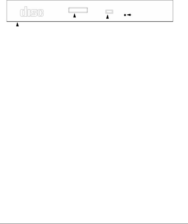
CD ROM Drive (Optional)
As an optional component, the J6000 workstations support one slim-line CD ROM drive with an ATAPI (IDE) interface.
Figure 1-4 shows the operating features of the CD ROM drive, and Table 1-3 describes these features.
Figure 1-4. CD ROM Drive Features
|
|
|
|
|
Emergency Eject |
|
|
|
|
|
|
Button |
|
|
|
|
|
|
||
|
|
|
|
|
|
|
|
|
Eject Button |
Busy Indicator |
|||
|
|
|||||
Disk Tray |
|
|
Light |
|||
Table 1-3. CD ROM Drive Features |
|
|
|
|||
|
|
|
|
|
|
|
Feature |
Purpose |
|
|
|
||
|
|
|
|
|
|
|
Busy Indicator |
• Lights during a data access operation and during a data |
|
||||
|
|
transfer. |
|
|
|
|
|
|
• Flashes at a one second rate when a disk is loaded. |
|
|||
|
|
• Continues to flash if a disk or hardware error is detected. |
|
|||
|
|
• Flashes at a three second rate while playing an audio disk. |
|
|||
|
|
|
|
|
|
|
Emergency |
Opens the Disk Tray when the end of a paper clip is inserted |
|
||||
Eject Hole |
into it. Used when the workstation does not have power and |
|
||||
|
|
the Disk Tray cannot be opened by pressing the Eject Button. |
|
|||
|
|
|
|
|
|
|
Eject Button |
Opens the Disk Tray so that a CD ROM disk may be inserted |
|
||||
|
|
in it or removed from it. When the drive is in use, press the |
|
|||
|
|
Eject Button for more than one second to open the Disk Tray. |
|
|||
|
|
The Disk Tray does not open if the workstation power is off. |
|
|||
|
|
|
|
|
|
|
Disk Tray |
Holds the CD ROM disk. (Note that this style of CD ROM |
|
||||
|
|
drive does not use a disk caddy.) |
|
|
|
|
|
|
|
|
|
|
|
24 |
Chapter 1 |
LVD Product Information
Rear Panel Components
Rear Panel Components
This section describes the following components on the system unit’s rear panel. Figure 1-5 shows the locations of these rear panel components.
•Power cord connector
•Transfer of Control (TOC) Button
•Audio connectors
•Two serial ports
•802.3 Twisted Pair (TP) LAN connector
•Two USB connectors
•Single-Ended/Low-Voltage Differential (SE/LVD) SCSI connector
NOTE To maintain FCC/EMI compliance, verify that all cables are fully seated and properly fastened.
Figure 1-5. System Unit Rear Panel Connectors
Power Connector |
Serial Port 1 |
LAN Connector |
|
|
I/O Card Slots |
||
|
Serial Port 2 |
|
|
|
|
|
|
|
|
|
|
|
|
1 |
slot 1 |
|
|
|
|
|
|
|
|
|
IOIOI 1 |
SERIAL |
|
|
|
2 |
slot 2 |
|
|
|
|
|
|
|
|
|
|
|
USB |
|
|
|
slot 3 |
|
2 |
|
LAN TP 10/100 |
|
|
3 |
|
|
|
SE |
SCSI |
LVD |
|||
|
|
|
|
||||
|
|
|
|
COMPATIBLE CABLE REQUIRED |
|
|
|
TOC |
USB Connectors |
|
15-Pin D-Sub |
||
|
|
|
|
Connector |
|
|
|
|
|
||
|
|
|
|
SE/LVD |
(optional graphics card) |
Audio Connectors |
SCSI |
|
|||
Connector |
|
||||
|
|
|
|
|
|
Chapter 1 |
25 |

LVD Product Information
Rear Panel Components
Connectors on the Rear Panel
Power Cord Connector
Plug the power cord into the power cord connector to provide AC power to the workstation. The J6000 power cord is rated at 15A for a 100–120V source.
RS-232C Serial Connectors
You can attach a variety of pointing devices (such as a mouse or trackball) or peripheral devices (such as printers, plotters, modems, and scanners) to the RS-232C Serial Input/Output (SIO) ports on this workstation. Consult the documentation that accompanies the device for specific information concerning its use.
LAN 10/100 BaseT RJ45 Connector
Your workstation has a built-in Twisted Pair (TP) connector for the 802.3 (ETHERNET) or 10 BaseT/100 BaseT network. Your workstation will automatically select the correct network setting.
USB Connectors
The two Universal Serial Bus (USB) connectors support only the HP keyboard, mouse, or hub (D6804A). You can connect the HP keyboard, mouse, or hub in either of the USB connectors.
The USB mouse and keyboard were shipped with your system unit. The HP hub can be ordered separately. Note that you should consult the documentation that accompanies each input device for specific information concerning its use.
For more information on the Universal Serial Bus, use your browser to access the following URL: http://www.usb.org.
HP Hub for USB Devices
The HP USB hub provides you with the ability to connect more than two USB devices to the workstation, as well as the ability to extend the USB device’s cable length. As an example, you may desire to locate the workstation’s keyboard and mouse at a greater distance from the workstation, but the keyboard and mouse cables are not long enough. To increase the cable length, you must make use of the USB hub’s extra cable length and connect the hub’s cable to one of the two connectors on the back of the workstation. You then connect the keyboard and mouse into their separate connectors on the USB hub.
26 |
Chapter 1 |
LVD Product Information
Rear Panel Components
SCSI Connectors
There is one Single-Ended/Low-voltage Differential (SE/LVD) SCSI connector on the rear panel. This connector will support SE SCSI and LVD SCSI, but not both at the same time. Use the SCSI connector to connect external SCSI devices such as hard disk drives, optical disk drives, DDS-format tape drives, and CD ROM drives.
Consult the documentation that accompanies each SCSI device for specific information concerning its use. Also see Appendix C, “SCSI Connections,” for information about connecting SCSI devices to the J6000 workstations.
CAUTION Do not mix SE and LVD SCSI devices on the same SCSI bus as this can cause reduction of device performance.
Audio Connectors
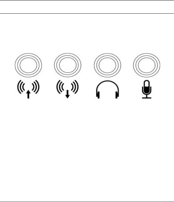
Your workstation has audio input and output capability through external input and output connectors on the rear panel and through an internal speaker. The rear panel contains the line input jack, line output jack, headphone jack, and microphone jack connectors.
Figure 1-6. Audio Connectors
Line Input |
Line Output |
Headphone |
Microphone |
The audio connectors are standard stereo audio mini-jacks. Hewlett-Packard recommends using gold-plated plugs available through audio retailers for best quality recording and playback through the external connectors. Table 1-4 on the next page provides a summary of the audio electrical specifications.
Table 1-4. Audio Electrical Specifications
Frequency Response |
25 Hz to 20 kHz |
|
|
Input Sensitivity/Impedance: |
|
– Line in |
2.0 Vpk/47 Kohm |
– Microphone |
22 mVpk/1 Kohm |
|
|
Chapter 1 |
27 |

LVD Product Information
Rear Panel Components
Table 1-4. Audio Electrical Specifications
Maximum Output |
|
Level/Impedance: |
|
– Line out |
2.8 Vpp/47 Kohm |
– Headphones |
2.8 Vpp/50 ohm |
– Speaker (internal) |
5.9 Vpp/48 ohm |
|
|
Output Impedance: |
|
– Line out |
619 ohm |
– Headphones |
118 ohm |
|
|
28 |
Chapter 1 |
 J6000 User Manual")
LVD Product Information
Internal Components
Internal Components
This section describes the internal components of the J6000 workstations.
For instructions on how to remove the workstation’s top panel in order to access the PCI cage, memory cards (DIMMs), CD ROM drive, and hard disk drive(s), as well as instructions on how to install and remove them, see Chapter 4.
Figure 1-7. Internal Components of the J6000
16 Memory Slots
Processor 0 Processor 1
 VRMs
VRMs
System Board
The system board in the J6000 contains the PA-RISC microprocessors, memory slots, and PCI cage as well as connectors to other components.
Chapter 1 |
29 |

LVD Product Information
Internal Components
Microprocessors
The J6000 has two PA-8600 microprocessors with operating frequencies of 552 MHz. Each processor has 0.5 MB instruction cache and a 1.0 MB data cache. Each microprocessor is cooled by a “turbocooler” which consists of a cylindrical heat sink and an integrated fan.
Power Supply
The power system is comprised of one apparent power factor 500W output power supply. The maximum power needed by a fully-configured SPU is 715W input power. The temperature sensor is located in the front of the power supply. The power supply weighs approximately 8 lbs. (4 kg.). Please note that the system speaker is located in the power supply.
CAUTION HP does not recommend and does not support the use of “ferro-active” or “ferro-resonant” power correction in conjunction with the J6000 workstation. This type of line conditioner represents an older technology that is not compatible with the most recent designs in active Power Factor Correction (PFC) power supplies such as those in the HP J6000 workstations. “Ferro-active” or “ferro-resonant” line conditioners may cause an increase in total harmonic distortion and may produce significant and unpredictable voltage regulation anomalies.
PCI Cage
The PCI (Peripheral Connect Interface) cage is located on the left side of the system board, behind the CD ROM and hard disk drive bays. There are three PCI-4X, 64 bit, 3.3v, 66 MHz slots which provide I/O expansion capabilities for the workstation. There are no primary and secondary card slots.
CD ROM and Hard Disk Drive Bays
The J6000 supports two Low-Voltage Differential (LVD) SCSI hard disk drives (one standard and one optional) and one optional ATAPI slim-line CD ROM drive. The internal SCSI Bus is independent of the external SCSI Bus.
The hard disk drives are hot-pluggable. More information on this was provided earlier in this chapter in the Hard Disk Drive section.
Voltage Regulator Modules (VRMs)
NOTE These VRMs are designed to function ONLY with the J6000 power supply. The output is 2VDC. The maximum current is 52A.
30 |
Chapter 1 |
Loading...