


Product End-of-Life Disassembly Instructions
Product Category: Notebooks and Tablet PCs
Marketing Name / Model
[List multiple models if applicable.]
HP 620 Notebook PC
Name / Model #2
Name / Model #3
Name / Model #4
Name / Model #5
Purpose: The document is intended for use by end-of-life recyclers or treatment facilities. It provides the basic instructions for the disassembly of HP products to remove components and materials requiring selective treatment, as defined by EU directive 2002/96/EC, Waste Electrical and Electronic Equipment (WEEE).
1.0Items Requiring Selective Treatment
1.1Items listed below are classified as requiring selective treatment.
1.2Enter the quantity of items contained within the product which require selective treatment in the right column, as applicable.
|
|
|
|
|
|
|
Quantity |
|
|
Item Description |
|
Notes |
|
of items |
|
||
|
|
|
included |
|
||||
|
|
|
|
|
|
|
|
|
|
|
|
|
|
|
|
in product |
|
|
Printed Circuit Boards (PCB) or Printed Circuit |
|
|
With a surface greater than 10 sq cm |
|
3 |
|
|
|
Assemblies (PCA) |
|
|
|
|
|
|
|
|
Batteries |
|
All types including standard alkaline and lithium coin |
2 |
|
|||
|
|
|
|
or button style batteries |
|
|
|
|
|
Mercury-containing components |
|
For example, mercury in lamps, display backlights, |
|
1 |
|
||
|
|
|
|
scanner lamps, switches, batteries |
|
|
|
|
|
Liquid Crystal Displays (LCD) with a surface greater |
|
Includes background illuminated displays with gas |
1 |
|
|||
|
than 100 sq cm |
|
discharge lamps |
|
|
|
||
|
Cathode Ray Tubes (CRT) |
|
|
|
0 |
|
||
|
Capacitors / condensers (Containing PCB/PCT) |
|
|
|
0 |
|
||
|
|
|
|
|
|
|
|
|
|
Electrolytic Capacitors / Condensers measuring |
|
|
|
|
0 |
|
|
|
greater than 2.5 cm in diameter or height |
|
|
|
|
|
|
|
|
External electrical cables and cords |
|
|
|
0 |
|
||
|
Gas Discharge Lamps |
|
|
|
0 |
|
||
|
Plastics containing Brominated Flame Retardants |
|
|
|
0 |
|
||
|
|
|
|
|
|
|
|
|
|
Components and parts containing toner and ink, |
|
|
Include the cartridges, print heads, tubes, vent |
|
0 |
|
|
|
including liquids, semi-liquids (gel/paste) and toner |
|
|
chambers, and service stations. |
|
|
|
|
|
Components and waste containing asbestos |
|
|
|
0 |
|
||
|
Components, parts and materials containing |
|
|
|
|
0 |
|
|
|
refractory ceramic fibers |
|
|
|
|
|
|
|
|
EL-MF877-00 |
|
|
|
|
Page 1 |
||
Template Revision A |
|
|
|
|
|
|
||

Components, parts and materials containing |
|
0 |
radioactive substances |
|
|
|
|
|
2.0 Tools Required
List the type and size of the tools that would typically be used to disassemble the product to a point where components and materials requiring selective treatment can be removed.
Tool Description |
|
Tool Size (if |
|
|
|
|
|
applicable) |
|
Description #1 |
Motor-screw-driver “+” |
|
Cross head |
|
|
of screwdriver |
|
||
|
|
|
|
|
Description #2 |
Motor-screw-driver “*” |
|
TORX T8 |
|
|
(2.31mm) |
|||
|
|
|
||
Description #3 |
Motor-screw-driver “-” |
|
|
|
|
|
|
|
|
|
|
|
|
|
|
|
|
|
|
3.0Product Disassembly Process
3.1List the basic steps that should typically be followed to remove components and materials requiring selective treatment:
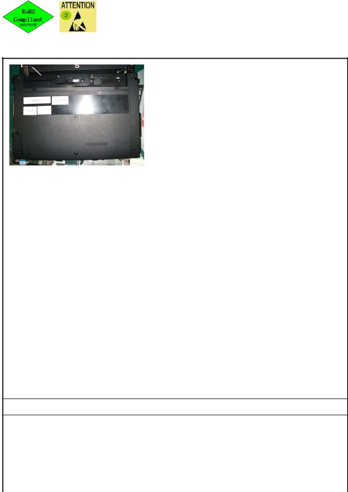
1.Follow steps described in Disassembly instruction (file attached).
2.If parts can be removed without using a tool, remove it first.
3.Use correct screwdriver and torque value before unlock the screw.
5..
3.2 Optional Graphic. If the disassembly process is complex, insert a graphic illustration below to identify the items contained in the product that require selective treatment (with descriptions and arrows identifying locations).
EL-MF877-00 |
Page 2 |
Template Revision A |
|
MANUFACTURING PROCESS INSTRUCTIONS
MECHANICAL ASSEMBLY
MODEL : VV10
Sub-assembly name: |
VV10 FA DIS-ASS’Y |
|
|
|
|
|
|
|||||||
Document No.: |
|
SOP VV10 FA ASSY DIS-ASS’Y |
|
|
|
|
|
|||||||
Written by: |
|
|
Cui,Junhua |
|
|
Revision: |
|
0.10 |
||||||
Date: |
|
|
|
2010/3/8 |
|
|
|
Page: |
|
|
1 of 52 |
|||
A.Current station version list: |
|
|
|
|
|
|
|
|
|
|
||||
Station |
Version |
Station |
Version |
Station |
Version |
Station |
Version |
Station |
Version |
Station |
Version |
|||
|
|
|
|
|
|
|
|
|
|
|
|
|
|
|
1 |
0.10 |
11 |
0.10 |
21 |
0.10 |
|
31 |
0.10 |
41 |
0.10 |
|
|
51 |
0.10 |
2 |
0.10 |
12 |
0.10 |
22 |
0.10 |
|
32 |
0.10 |
42 |
0.10 |
|
|
52 |
0.10 |
3 |
0.10 |
13 |
0.10 |
23 |
0.10 |
|
33 |
0.10 |
43 |
0.10 |
|
|
|
|
4 |
0.10 |
14 |
0.10 |
24 |
0.10 |
|
34 |
0.10 |
44 |
0.10 |
|
|
|
|
5 |
0.10 |
15 |
0.10 |
25 |
0.10 |
|
35 |
0.10 |
45 |
0.10 |
|
|
|
|
6 |
0.10 |
16 |
0.10 |
26 |
0.10 |
|
36 |
0.10 |
46 |
0.10 |
|
|
|
|
7 |
0.10 |
17 |
0.10 |
27 |
0.10 |
|
37 |
0.10 |
47 |
0.10 |
|
|
|
|
8 |
0.10 |
18 |
0.10 |
28 |
0.10 |
|
38 |
0.10 |
48 |
0.10 |
|
|
|
|
9 |
0.10 |
19 |
0.10 |
29 |
0.10 |
|
39 |
0.10 |
49 |
0.10 |
|
|
|
|
10 |
0.10 |
20 |
0.10 |
30 |
0.10 |
|
40 |
0.10 |
50 |
0.10 |
|
|
|
|
B.Version Modify list: |
|
|
|
|
|
|
|
|
|
|
|
|||
Date |
Station |
|
|
Content |
|
|
Ver. |
|
|
Design |
||||
2010/3/8 |
ALL |
First SOP for mass production |
|
|
0.1* |
|
|
Cui,Junhua |
||||||
|
|
|
|
|
|
|
|
|
|
|
|
|
|
|
|
|
|
|
|
|
|
|
|
|
|
|
|
|
|
|
|
|
|
|
|
|
|
|
|
|
|
|
|
|
|
|
|
|
|
|
|
|
|
|
|
|
|
|
|
|
|
|
|
|
|
|
|
|
|
|
|
|
|
|
|
|
|
|
|
|
|
|
|
|
|
|
|
|
|
|
|
|
|
|
|
|
|
|
|
|
|
|
|
|
|
|
|
|
|
|
|
|
|
|
|
|
|
|
|
|
|
|
|
|
|
|
|
|
|
|
|
|
|
|
|
|
|
|
|
|
|
|
|
|
|
|
|
|
|
|
|
|
|
|
|
|
|
|
|
|
|
|
|
|
|
|
|
|
|
|
|
|
|
|
|
|
|
|
|
|
|
|
|
|
|
|
|
|
|
|
|
|
|
|
|
|
|
|
|
|
|
|
|
|
|
|
|
|
|
|
|
|
|
|
|
|
|
|
|
|
|
|
|
|
|
|
|
|
|
|
|
|
|
|
|
|
|
|
|
Auditor |
Tabulator Zhang, Ying |
||
|
|
|
|
Working Instruction
Document No. : SOP VV10 FA |
|
|
Station : |
1(1/1) |
|
Name |
: Disassemble Battery |
Ver. : |
0.20 |
Date : |
2010/03/08 |
|
|||||
STEP
1. Disassemble Battery (Fig.1)
Fig.1
Point for attention If finding some defects, notice the gaffer and assistant
Fixture list Fixture standard |
Qty |
Fixture list Fixture standard |
Qty |
|
|
|
|
Notebook |
1 |
|
|
Scanner |
1 |
|
|
Bar code printer |
1 |
|
|
|
|
|
|
Tabulator _Zhang Ying_ |
Issuing department IE |
Working Instruction
Document No. : SOP VV10 FA |
|
|
Station : |
2(1/1) |
|
Name |
:Loosen screws & Disassemble Cover |
Ver. : |
0.20 |
Date : |
2010/03/08 |
|
|||||
STEP
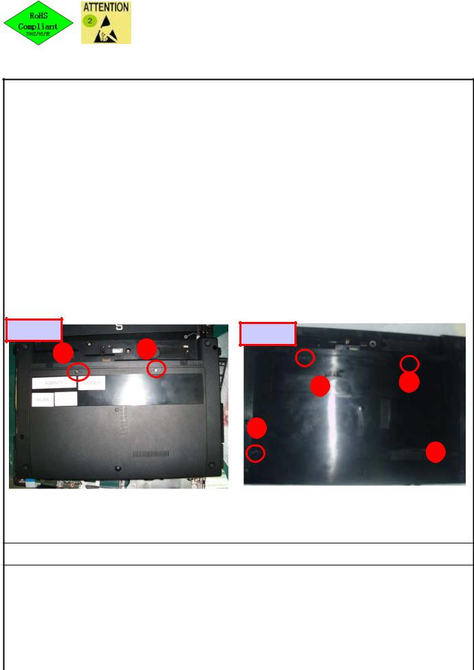
1. Loosen SET screwsTorsion 1.0 ± 0.2 Kgf cm
13&14 Loosen screws*2 15 Loosen screws*4
2. Disassemble Cover
13” & 14” |
6070B0431301 |
|
|
15” |
6070B0431201 |
|
|
13/14” |
|
15” |
|
|
|
|
1 |
2 |
|
|
2 |
3 |
|
1
4 
Point for attention If finding some defects, notice the gaffer and assistant
Fixture list Fixture standard |
Qty |
Fixture list Fixture standard |
Qty |
|
|
|
|
Automatic crossing screw driver |
1 |
|
|
|
|
|
|
Tabulator _Zhang Ying_ |
Issuing department IE |
Working Instruction
Document No. : SOP VV10 FA |
|
|
Station : |
3(1/1) |
|
Name |
:Loosen screws & Disassemble ODD |
Ver. : |
0.20 |
Date : |
2010/03/08 |
|
|||||
STEP
For All
1.Loosen screws (60520D046304) * 1 and
Disassemble ODD
Torsion 2.0 ± 0.2Kgf cm
Screws can't be stripped.
For 13&14 |
For 15” |
ODD
ODD screws
ODD
ODD screws
Point for attention If finding some defects, notice the gaffer and assistant
Fixture list Fixture standard |
Qty |
Fixture list Fixture standard |
Qty |
|
|
|
|
Automatic crossing screw driver(T8) |
1 |
|
|
|
|
|
|
Tabulator _Zhang Ying_ |
Issuing department IE |
Working Instruction
Document No. : SOP VV10 FA |
|
|
Station : |
4(1/1) |
|
Name |
:Disassemble HDD &Loosen screws |
Ver. : |
0.20 |
Date : |
2010/03/08 |
|
|||||
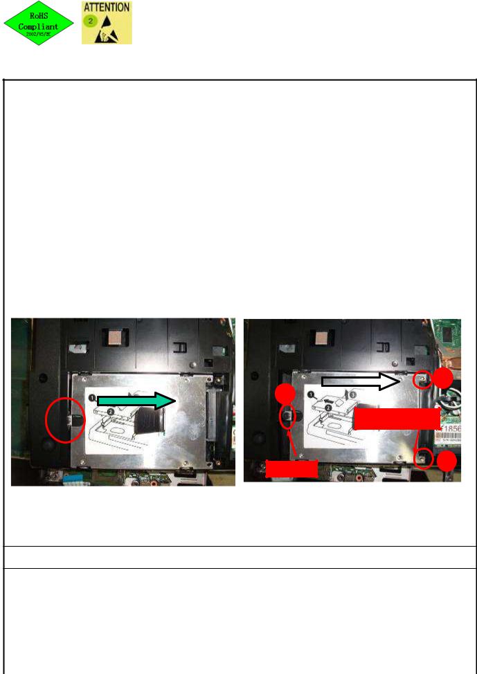
STEP
1. Loosen HDD screws(6052B0080701) * 2 and setscrews 1
Torsion 2.0 ±0.2Kgf cm
Screws can't be stripped.
2. Disassemble HDD and take it out
 2 1
2 1 
6052B0080701
3
SET screws
Point for attention If finding some defects, notice the gaffer and assistant
Fixture list Fixture standard |
Qty |
Fixture list Fixture standard |
Qty |
|
|
|
|
Automatic crossing screw driver |
1 |
|
|
|
|
|
|
Tabulator _Zhang Ying_ |
Issuing department IE |

Working Instruction
|
Document No. : SOP VV10 FA |
|
|
Station : 5(1/1) |
||||
|
|
|
|
|
|
|
|
|
|
Name |
|
: Disassemble Antenna Cable |
Ver. : |
0.20 |
Date : 2010/03/08 |
||
|
||||||||
|
|
|
|
STEP |
||||
|
|
|
|
|
|
|
|
|
|
13” |
|
|
|
1.Disassemble Antenna interface from |
|||
|
|
|
|
|
WLAN |
|||
|
|
|
|
|
2.Disassemble Antenna Cable |
|||
|
|
|
|
|
||||
15”
14”
Point for attention If finding some defects, notice the gaffer and assistant
Fixture list Fixture standard |
Qty |
Fixture list Fixture standard |
Qty |
|
|
|
|
|
|
|
|
Tabulator _Zhang Ying_ |
Issuing department IE |
Working Instruction
Document No. : SOP VV10 FA |
|
Station : |
6(1/1) |
|
Name |
: Loosen screws & Disassemble WLAN Ver. : |
0.20 |
Date : |
2010/03/08 |
|
||||
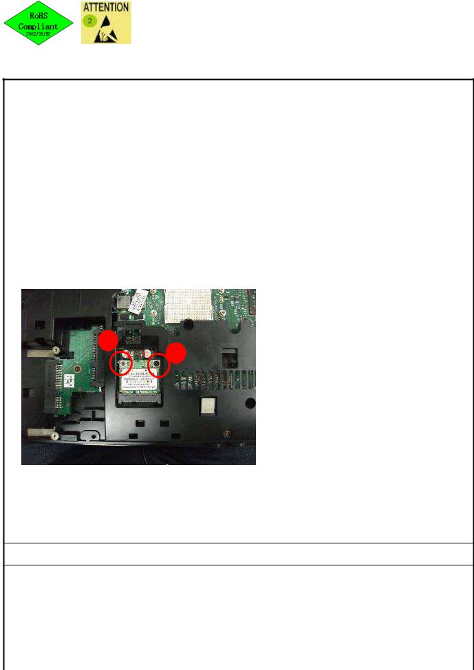
STEP
1.Loosen WLAN Screws(6052B0156101) * 2
Torsion 1.5 ± 0.2Kgf cm
Screws can't be stripped.
2.Take out WLAN
1
2
Point for attention If finding some defects, notice the gaffer and assistant
Fixture list Fixture standard |
Qty |
Fixture list Fixture standard |
Qty |
|
|
|
|
Automatic crossing screw driver |
1 |
|
|
|
|
|
|
Tabulator _Zhang Ying_ |
Issuing department IE |
Working Instruction
Document No. : SOP VV10 FA |
|
|
Station : |
7(1/1) |
|
Name |
: Loosen screws |
Ver. : |
0.20 |
Date : |
2010/03/08 |
|
|||||
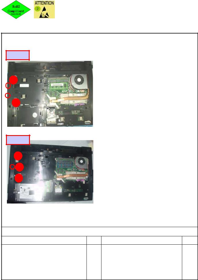
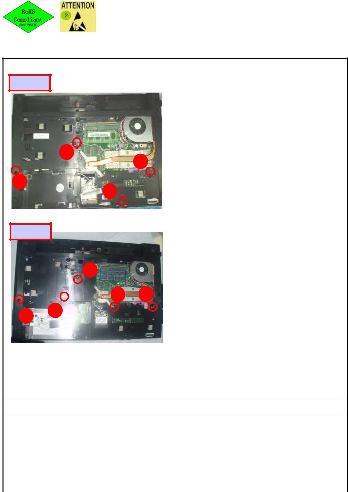
STEP
13/14”
1
2
15”
 1
1
2
 3
3
1. Loosen screws (6052B0156101)Torsion 1.5 ± 0.2 Kgf cm
13”&14”Loosen 2 screws,15”Loosen 2 screwsScrews can't be stripped.
Point for attention If finding some defects, notice the gaffer and assistant
Fixture list Fixture standard |
Qty |
Fixture list Fixture standard |
Qty |
Automatic crossing screw driver
1
Tabulator _Zhang Ying_ |
Issuing department IE |
Working Instruction
Document No. : SOP VV10 FA |
|
|
Station : |
8(1/1) |
|
Name |
: Disassemble FAN / BATT Cable |
Ver. : |
0.20 |
Date : |
2010/03/08 |
|
|||||
STEP
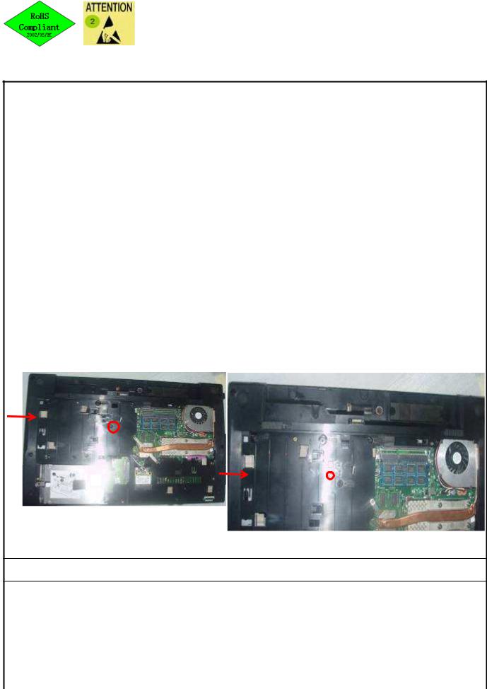
1.Disassemble BATT Cable
2.Disassemble FAN Cable
Point for attention If finding some defects, notice the gaffer and assistant
Fixture list Fixture standard |
Qty |
Fixture list Fixture standard |
Qty |
|
|
|
|
|
|
|
|
Tabulator _Zhang Ying_ |
Issuing department IE |
Working Instruction
|
Document No. : SOP VV10 FA |
|
|
Station : 9(1/1) |
||
|
|
|
|
|
|
|
|
Name |
: Loosen screws |
Ver. : |
0.20 |
Date : 2010/03/08 |
|
|
||||||
|
FOR 13” & 14” |
|
STEP |
|||
1 |
2 |
1. Loosen screws (6052B0096201) of SW |
||||
|
|
|
cover *3 |
|||
|
|
|
Torsion 2.0 ± 0.2 Kgf cm |
|||
13”&14”Loosen 3 screws 15” Loosen 4screws
Screws can't be stripped.
3
FOR 15”
1 |
2 |
3 |
4
Point for attention If finding some defects, notice the gaffer and assistant
Fixture list Fixture standard |
Qty |
Fixture list Fixture standard |
Qty |
|
|
|
|
Automatic crossing screw driver |
1 |
|
|
|
|
|
|
Tabulator _Zhang Ying_ |
Issuing department IE |
Working Instruction
Document No. : SOP VV10 FA |
|
Station : |
10(1/1) |
|
Name |
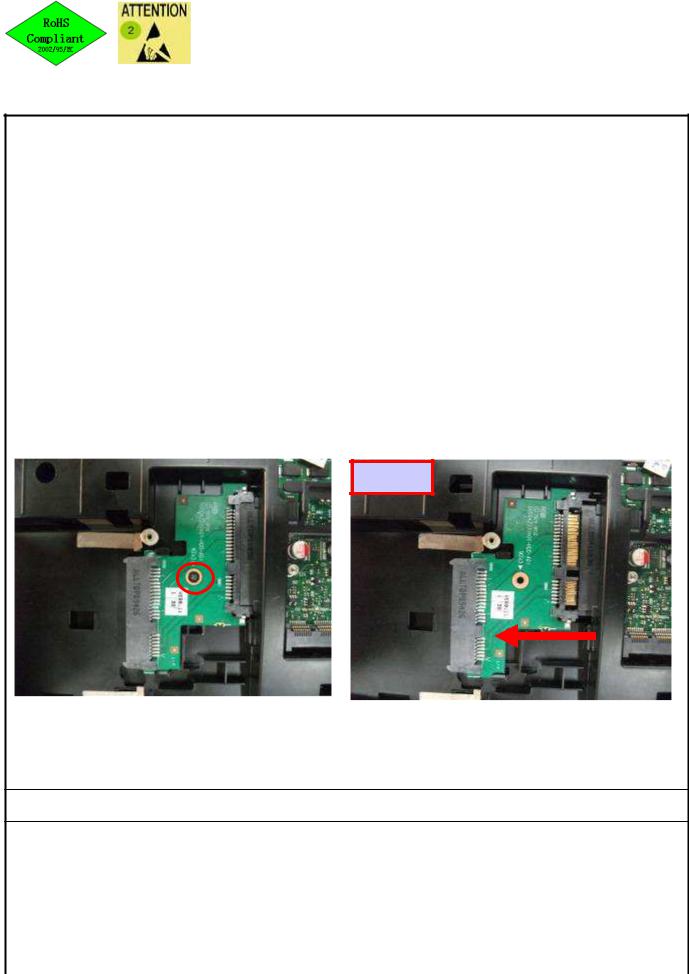
:Disassemble HDD extension board(for Ver. : |
0.20 |
Date : |
2010/03/08 |
|
||||
15’)
STEP
FOR 15” ONLY
1.Loosen screws (6052B0156101) * 1
Torsion 2.0 ± 0.2 Kgf cm
Screws can't be stripped.
2.Take out HDD extension board (1310A2330401)
15”
|
Loosen screws |
|
|
|
|
Take out CNTR ODD from extension board |
|
|
|
|
|
|
|
|
|
Point for attention If finding some defects, notice the gaffer and assistant
Fixture list Fixture standard |
Qty |
Fixture list Fixture standard |
Qty |
|
|
|
|
Automatic crossing screw driver(1#) |
1 |
|
|
|
|
|
|
Tabulator _Zhang Ying_ |
Issuing department IE |
Working Instruction
Document No. : SOP VV10 FA |
|
|
Station : |
11(1/1) |
|
Name |
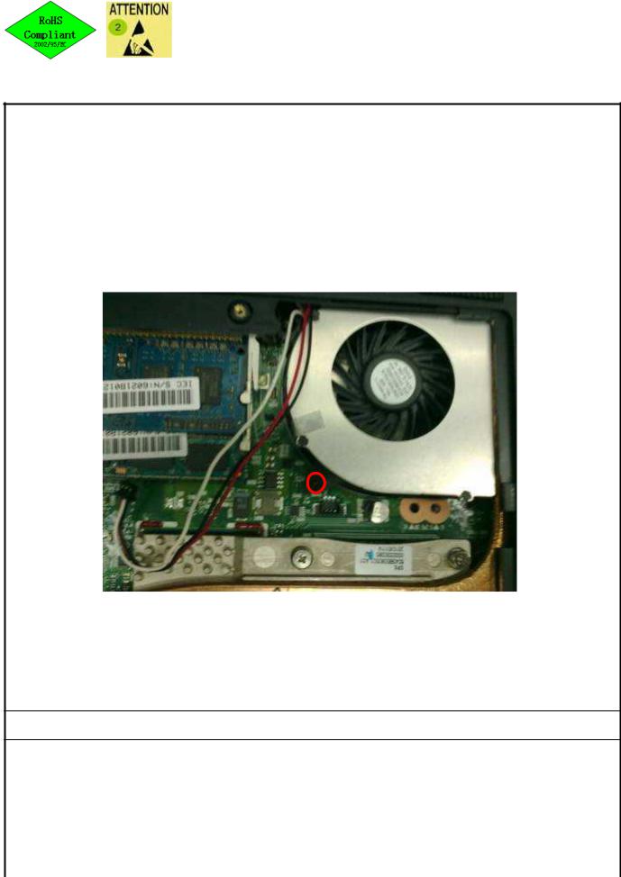
: Disassemble FAN |
Ver. : |
0.20 |
Date : |
2010/03/08 |
|
|||||
STEP
For 13&14:
1.Loosen FAN screws (6052B0156101) * 1Torsion 2.0 ± 0.2 Kgf cm
Screws can't be stripped.
2.Take out FAN (6033B0014602)
1
Point for attention If finding some defects, notice the gaffer and assistant
Fixture list Fixture standard |
Qty |
Fixture list Fixture standard |
Qty |
|
|
|
|
Automatic crossing screw driver |
1 |
|
|
|
|
|
|
Tabulator _Zhang Ying_ |
Issuing department IE |
Working Instruction
Document No. : SOP VV10 FA |
|
|
Station : 12(1/1) |
|||
|
|
|
|
|
|
|
Name |
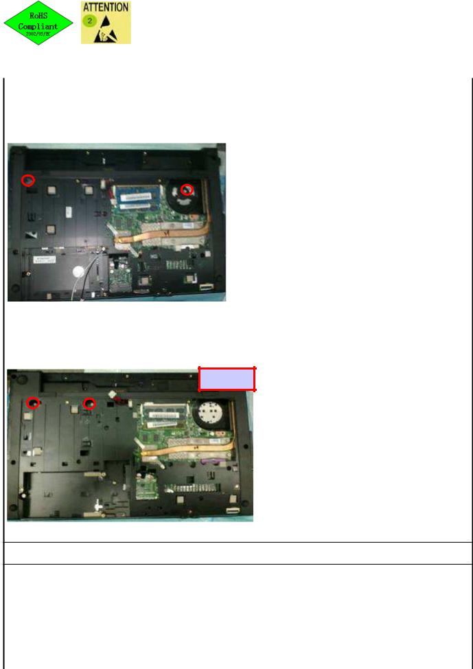
: Loosen screws |
Ver. : |
0.20 |
Date : 2010/03/08 |
||
|
||||||
|
|
|
STEP |
|||
|
|
|
1. Loosen screws (6052B0097001)*2 of K/B . |
|||
|
|
|
Torsion 2.0 ± 0.2 Kgf cm |
|||
|
|
13/14” |
Screws can't be stripped. |
|||
|
1 |
|
|
|
|
|
|
|
|
|
|
|
|
|
2 |
|
|
|
|
|
15”
1
2
Point for attention If finding some defects, notice the gaffer and assistant
Fixture list Fixture standard |
Qty |
Fixture list Fixture standard |
Qty |
|
|
|
|
Automatic crossing screw driver |
1 |
|
|
|
|
|
|
Tabulator _Zhang Ying_ |
Issuing department IE |
Working Instruction
Document No. : SOP VV10 FA |
|
|
Station : |
13(1/1) |
|
Name |
: 15” ONLY – Loosen screws |
Ver. : |
0.20 |
Date : |
2010/03/08 |
|
|||||
STEP
FOR 15” ONLY
1. Loosen screws (60520D046304) * 4
Torsion 2.0 ± 0.2 Kgf cm
Screws can't be stripped.
15”
4
3
1
2
Point for attention If finding some defects, notice the gaffer and assistant
Fixture list Fixture standard |
Qty |
Fixture list Fixture standard |
Qty |
|
|
|
|
Automatic crossing screw driver(T8) |
1 |
|
|
|
|
|
|
Tabulator _Zhang Ying_ |
Issuing department IE |
Working Instruction
Document No. : SOP VV10 FA |
|
|
Station : |
14(1/1) |
|
Name |
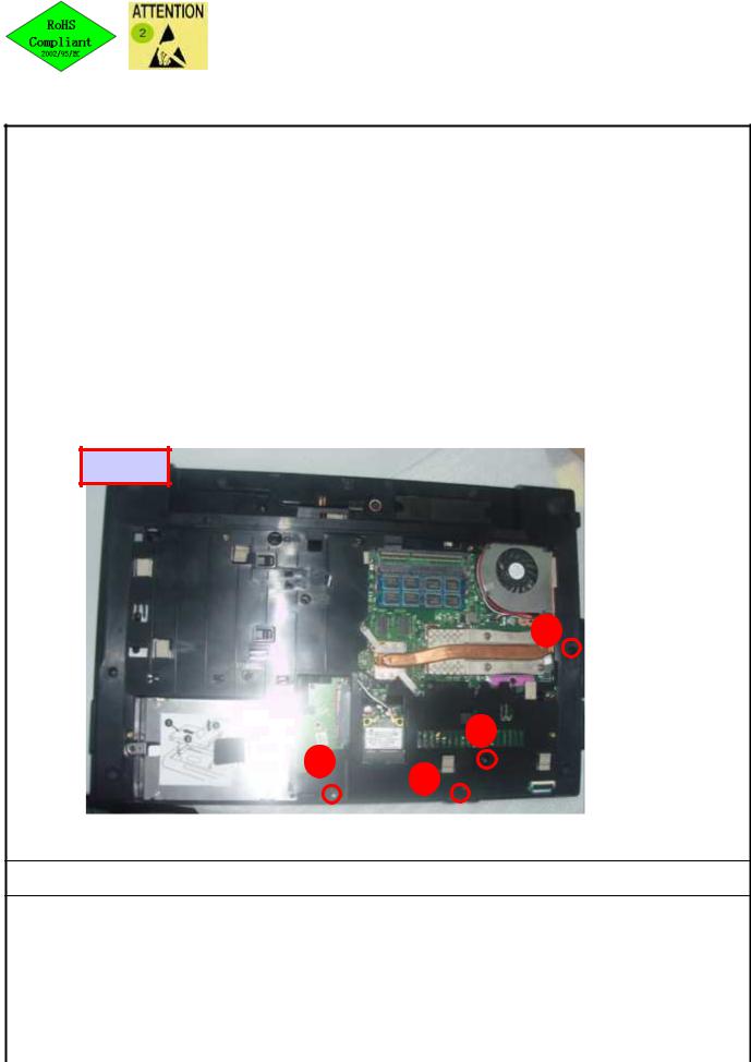
: Loosen screws |
Ver. : |
0.20 |
Date : |
2010/03/08 |
|
|||||
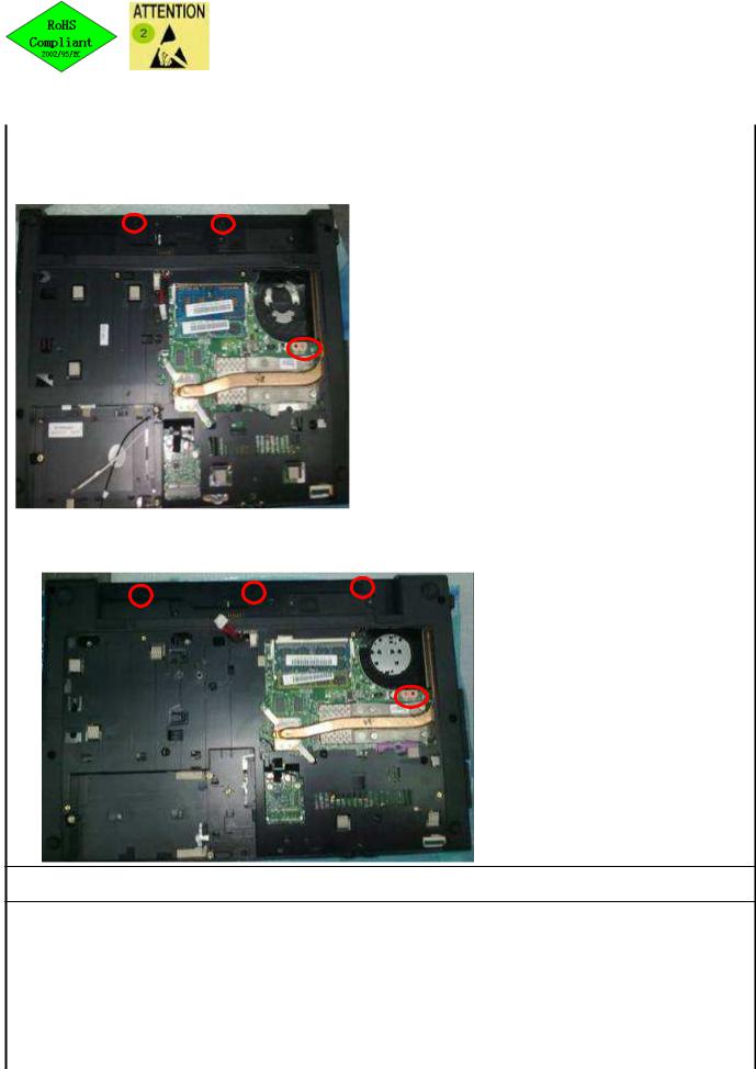
13/14”
2
4
1
3
15”
3
4 5
2
1
STEP
For 13&14:
1. Loosen screws (60520D046304) * 4
Torsion 2.0 ± 0.2 Kgf cm
Screws can't be stripped.
For 15:
1. Loosen screws (60520D046304) * 5
Torsion 2.0 ± 0.2 Kgf cm
Screws can't be stripped.
Point for attention If finding some defects, notice the gaffer and assistant
Fixture list Fixture standard |
Qty |
Fixture list Fixture standard |
Qty |
|
|
|
|
Automatic crossing screw driver(T8) |
1 |
|
|
|
|
|
|
Tabulator _Zhang Ying_ |
Issuing department IE |
 Loading...