


 Loading...
HP ENVY 17 Notebook PC
HP ENVY TouchSmart m7 Notebook PC HP ENVY TouchSmart 17 Notebook PC
Maintenance and Service Guide IMPORTANT! This document is intended for HP authorized service providers only.
© Copyright 2013 Hewlett-Packard
Development Company, L.P.
Bluetooth is a trademark owned by its proprietor and used by Hewlett-Packard Company under license. Intel is a trademark of Intel Corporation in the U.S. and other countries. Leap Motion, the Leap Motion logo, and Airspace are the trademarks of Leap Motion, Inc. and are used here by permission. Microsoft and Windows are U.S. registered trademarks of Microsoft Corporation. SD Logo is a trademark of its proprietor.
The information contained herein is subject to change without notice. The only warranties for HP products and services are set forth in the express warranty statements accompanying such products and services. Nothing herein should be construed as constituting an additional warranty. HP shall not be liable for technical or editorial errors or omissions contained herein.
Second Edition: August 2013
First Edition: April 2013
Document Part Number: 715237-002
Product notice
This guide describes features that are common to most models. Some features may not be available on your computer.
Not all features are available in all editions of Windows 8. This computer may require upgraded and/or separately purchased hardware, drivers, and/or software to take full advantage of Windows 8 functionality. See http://www.microsoft.com for details.
Software terms
By installing, copying, downloading, or otherwise using any software product preinstalled on this computer, you agree to be bound by the terms of the HP End User License Agreement (EULA). If you do not accept these license terms, your sole remedy is to return the entire unused product (hardware and software) within 14 days for a refund subject to the refund policy of your place of purchase.
For any further information or to request a full refund of the computer, please contact your local point of sale (the seller).

Important Notice about Customer Self-Repair Parts
CAUTION: Your computer includes Customer Self-Repair parts and parts that should only be accessed by an authorized service provider. See Chapter 5, "Removal and replacement procedures for Customer Self-Repair parts," for details. Accessing parts described in Chapter 6, "Removal and replacement procedures for Authorized Service Provider only parts," can damage the computer or void your warranty.
iii
iv Important Notice about Customer Self-Repair Parts

Safety warning notice
WARNING! To reduce the possibility of heat-related injuries or of overheating the device, do not place the device directly on your lap or obstruct the device air vents. Use the device only on a hard, flat surface. Do not allow another hard surface, such as an adjoining optional printer, or a soft surface, such as pillows or rugs or clothing, to block airflow. Also, do not allow the AC adapter to contact the skin or a soft surface, such as pillows or rugs or clothing, during operation. The device and the AC adapter comply with the user-accessible surface temperature limits defined by the International Standard for Safety of Information Technology Equipment (IEC 60950).
v
vi Safety warning notice

Table of contents
1 |
Product description ........................................................................................................... |
1 |
|
Service tag and PCID label ....................................................................................................... |
6 |
|
Service tag ............................................................................................................... |
6 |
|
PCID label ................................................................................................................ |
6 |
2 |
External component identification ..................................................................................... |
8 |
|
Display ................................................................................................................................... |
8 |
|
Buttons and speakers ................................................................................................................ |
9 |
|
Keys ..................................................................................................................................... |
11 |
|
Lights .................................................................................................................................... |
12 |
|
TouchPad .............................................................................................................................. |
13 |
|
Left side ................................................................................................................................ |
14 |
|
Right side .............................................................................................................................. |
15 |
|
Bottom .................................................................................................................................. |
17 |
3 |
Illustrated parts catalog .................................................................................................. |
19 |
|
Computer major components ................................................................................................... |
19 |
|
Display assembly subcomponents ............................................................................................. |
28 |
|
Mass storage devices ............................................................................................................. |
29 |
|
Miscellaneous parts ................................................................................................................ |
30 |
|
Sequential part number listing .................................................................................................. |
31 |
4 |
Removal and replacement procedures preliminary requirements .................................... |
40 |
|
Tools required ....................................................................................................................... |
40 |
|
Service considerations ............................................................................................................ |
40 |
|
Plastic parts ............................................................................................................ |
40 |
|
Cables and connectors ............................................................................................ |
41 |
|
Drive handling ........................................................................................................ |
41 |
|
Grounding guidelines ............................................................................................................. |
42 |
|
Electrostatic discharge damage ................................................................................. |
42 |
|
Packaging and transporting guidelines ....................................................... |
43 |
vii
|
Workstation guidelines ............................................................................. |
43 |
|
Equipment guidelines ................................................................................ |
44 |
5 |
Removal and replacement procedures for Customer Self-Repair parts ............................. |
45 |
|
Component replacement procedures ........................................................................................ |
45 |
|
Battery ................................................................................................................... |
46 |
|
Service cover .......................................................................................................... |
47 |
|
Hard drive ............................................................................................................. |
48 |
|
Memory modules .................................................................................................... |
51 |
|
WLAN module ........................................................................................................ |
52 |
|
Optical drive .......................................................................................................... |
55 |
6 |
Removal and replacement procedures for Authorized Service Provider parts .................. |
58 |
|
Component replacement procedures ........................................................................................ |
58 |
|
Display panel ......................................................................................................... |
59 |
|
RTC battery ............................................................................................................ |
63 |
|
Base enclosure ........................................................................................................ |
64 |
|
Front speakers ........................................................................................................ |
68 |
|
Optical drive connector board .................................................................................. |
69 |
|
Subwoofer ............................................................................................................. |
70 |
|
Display hinges and top cover ................................................................................... |
72 |
|
Display panel cable ................................................................................................ |
74 |
|
Webcamera/microphone module ............................................................................. |
75 |
|
WLAN antenna cables ............................................................................................ |
77 |
|
USB board ............................................................................................................. |
79 |
|
Fingerprint reader board .......................................................................................... |
81 |
|
Leap Motion module ................................................................................................ |
82 |
|
Power connector cable ............................................................................................ |
84 |
|
Fan ....................................................................................................................... |
85 |
|
System board ......................................................................................................... |
86 |
|
Heat sink ............................................................................................................... |
89 |
|
Processor ............................................................................................................... |
91 |
|
Keyboard ............................................................................................................... |
92 |
|
Rear speakers ......................................................................................................... |
95 |
|
Power button board ................................................................................................. |
97 |
|
TouchPad module .................................................................................................... |
98 |
7 |
Setup Utility (BIOS) and System Diagnostics .................................................................. |
100 |
|
Windows 8 – Computer Setup (BIOS) and Advanced System Diagnostics ................................... |
100 |
|
Using Setup Utility ................................................................................................. |
100 |
viii
|
Starting Setup Utility (BIOS) ..................................................................... |
100 |
|
Updating the BIOS ................................................................................. |
100 |
|
Determining the BIOS version ................................................... |
100 |
|
Downloading a BIOS update .................................................... |
101 |
|
Using System Diagnostics ......................................................... |
102 |
8 |
Specifications ................................................................................................................ |
103 |
|
Computer specifications ........................................................................................................ |
103 |
|
43.9-cm (17.3-in), HD+ display specifications ......................................................................... |
104 |
|
Hard drive specifications ...................................................................................................... |
105 |
9 |
Backing up, restoring, and recovering .......................................................................... |
106 |
|
Creating recovery media and backups ................................................................................... |
106 |
|
Creating HP Recovery media .................................................................................. |
107 |
|
Restore and recovery ............................................................................................................ |
108 |
|
Using Windows Refresh for quick and easy recovery ................................................. |
109 |
|
Remove everything and reinstall Windows ............................................................... |
109 |
|
Recovering using HP Recovery Manager .................................................................. |
110 |
|
What you need to know .......................................................................... |
111 |
|
Using the HP Recovery partition to recover a minimized image (select models |
|
|
only) ..................................................................................................... |
111 |
|
Using HP Recovery media to recover ........................................................ |
112 |
|
Changing the computer boot order ........................................................... |
112 |
|
Removing the HP Recovery partition ........................................................................ |
112 |
10 |
Power cord set requirements ...................................................................................... |
113 |
|
Requirements for all countries ................................................................................................ |
113 |
|
Requirements for specific countries and regions ....................................................................... |
114 |
11 |
Recycling .................................................................................................................... |
116 |
Index ............................................................................................................................... |
117 |
|
ix
x
1 Product description
Category |
Description |
|
|
Product Name |
HP ENVY 17 Notebook PC |
|
HP ENVY TouchSmart m7 Notebook PC |
|
HP ENVY TouchSmart 17 Notebook PC |
|
|
Processors |
● Intel® Quad Core™ i7-4900MQ 2.80-GHz (SC turbo up to 3.80-GHz) processor (1600-MHz |
|
FSB, 8.0-MB L3 cache, 47 W) |
|
● Intel Quad Core i7-4800MQ 2.70-GHz (SC turbo up to 3.70-GHz) processor (1600-MHz FSB, |
|
6.0-MB L3 cache, 47 W) |
|
● Intel Quad Core i7-4702MQ 2.20-GHz (SC turbo up to 3.20-GHz) processor (1600-MHz FSB, |
|
6.0-MB L3 cache, 37 W) |
|
● Intel Quad Core i7-4700MQ 2.40-GHz (SC turbo up to 3.40-GHz) processor (1600-MHz FSB, |
|
6.0-MB L3 cache, 47 W) |
|
● Intel Dual Core i5-4330M 2.80-GHz (SC turbo up to 3.50-GHz) processor (1600-MHz FSB, |
|
3.0-MB L3 cache, 37 W) |
|
● Intel Dual Core i5-4200M 2.50-GHz (SC turbo up to 3.10-GHz) processor (1600-MHz FSB, |
|
3.0-MB L3 cache, 37 W) |
|
● Intel Dual Core i5-3230M 2.60-GHz processor (1600-MHz FSB, 3.0-MB L3 cache, 37 W) |
|
● Intel Dual Core i3-4000M 2.40-GHz processor (1600-MHz FSB, 3.0-MB L3 cache, 37 W) |
|
● Intel Dual Core i3-3380M 2.90-GHz processor (1600-MHz FSB, 3.0-MB L3 cache, 37 W) |
|
● Intel Dual Core i3-3120M 2.50-GHz processor (1600-MHz FSB, 3.0-MB L3 cache, 37 W) |
|
|
Chipset |
Intel® HM87 Express Chipset |
|
|
|
Intel® HM77 Express Chipset |
|
|
Graphics |
Internal graphics: |
|
● Intel® HD Graphics 4600 internal graphics |
|
● Intel® HD Graphics 4000 internal graphics |
|
|
1

Category |
Description |
|
|
|
|
|
Switchable discrete graphics: |
|
|
● Nvidia N14P-GV2 (GeForce 740M) switchable discrete graphics with 2GB of dedicated video |
|
|
|
memory (128Mx16 DDR3 1GHz x 8 pcs) |
|
● Nvidia N14P-GT (GeForce 750M) switchable discrete graphics with 2GB of dedicated video |
|
|
|
memory (128Mx16 DDR3 1GHz x 8 pcs) |
|
|
|
Panel |
17.3" high-definition (HD) light-emitting diode (WLED) BrightView (1600x900) display, (wedge |
|
|
6.0mm) SVA, Color Gamut 60%, supports LVDS, 200 nits |
|
|
|
|
|
17.3" high-definition (FHD) light-emitting diode (WLED) AntiGlare (1920x1080) (wedge 6.0mm) |
|
|
WVA, Color Gamut 72%, supports LVDS, 300 nits |
|
|
|
|
|
Touchscreen, multitouch enabled, 160 nits (select models only) |
|
|
|
|
|
All display assemblies include 2 wireless local area network (WLAN) antenna cables. |
|
|
|
|
|
Supports 16:9 wide aspect ratio |
|
|
|
|
Memory |
Two customer-accessible/upgradable memory module slots |
|
|
DDR3L-1600MHz Dual Channel Support |
|
|
|
|
|
Supports up to 16-GB of system RAM in the following configurations: |
|
|
● 4096-MB total system memory (2048×2) |
|
|
● 4096-MB total system memory (4096×1) |
|
|
● 6144-MB total system memory (2048×1 + 4096×1) |
|
|
● 8192-MB total system memory (4096×2) |
|
|
● 8192-MB total system memory (8192×1) |
|
|
● 12288-MB total system memory (8192×1 + 4096×1) |
|
|
● 16384-MB total system memory (8192×2) |
|
|
|
|
Hard drives |
Supports 6.35-cm (2.5-in) hard drives in 9.5-mm (.37-in) and 7.0-mm (.28-in) thicknesses (all hard |
|
|
drives use the same bracket) |
|
|
Customer-accessible |
|
|
Serial ATA |
|
|
Supports the following hard drives: |
|
|
● |
1-TB 5400-rpm, 9.5-mm |
|
● |
750-GB 5400-rpm 9.5-mm |
|
● 500-GB 5400-rpm 9.5-mm and 7.0-mm |
|
|
|
|
|
Dual hard-drive configurations: |
|
● 2TB: (1-TB 5400-rpm x 2)
● 1500GB: (750-GB 5400-rpm x 2)
2 |
Chapter 1 Product description |

Category |
Description |
|
|
Solid-state drive |
Only configured with system memory up to 8 GB: |
|
● 32-GB mSATA (select models only) |
|
● 24-GB mSATA (select models only) |
|
|
Optical drives |
Fixed |
|
Serial ATA |
|
9.5-mm tray load |
|
Supports the following optical drives: |
|
● DVD+/-RW Double-Layer SuperMulti |
|
● Blu-ray Disc ROM with SuperMulti DVD±R/RW Double-Layer |
|
● Blu-ray Disc writer with SuperMulti DVD±R/RW Double-Layer |
|
● Support Zero-Power ODD |
|
|
External optical |
External USB |
drives |
Serial ATA |
|
|
|
12.7-mm tray load |
|
Supports the following external optical drives: |
|
● DVD+/-RW Double-Layer SuperMulti |
|
|
Audio and video |
Quad integrated stereo speakers and subwoofer |
|
HD Beats audio |
|
HP TrueVision high-definition webcam (fixed, no tilt + activity LED, 1PC, USB 2.0 M-JPEG, |
|
1280×720 by 30 frames per second) |
|
Dual array digital microphones with appropriate software - beam forming, echo cancellation, noise |
|
suppression |
|
|
Ethernet |
Integrated 10/100/1000 GB network interface card (NIC) |
|
|
3

Category |
Description |
|
|
Wireless |
Integrated wireless local area network (WLAN) options by way of wireless module |
|
Two WLAN antennas built into display assembly |
|
Supports Intel Wireless Display (WiDi) |
|
Antenna support for 802.11a/b/g/n with MIMO support 2×2 |
|
Supports the following WLAN formats: |
|
● Intel® Centrino® Wireless-N 2230 802.11 b/g/n 2×2 WiFi and Bluetooth 4.0 Combo |
|
Adapter |
|
● Realtek RTL8188EE 802.11 b/g/n 1x1 Wi-Fi Adapter |
|
● Qualcomm Atheros AR9485 802.11 b/g/n 1x1 Wi-Fi Adapter |
|
● Mediatek MT7630E 802.11 b/g/n 1×1 Wi-Fi and Bluetooth 4.0 combo adapter |
|
● Ralink RT3290LE 802.11bgn 1x1 Wi-Fi + BT 4.0 Combo Adapter |
|
|
External memory |
Push-push insertion/removal |
card |
Supports memory cards such as Secure Digital (SD). |
|
|
|
|
Internal card |
● One half-size mini-card slot for WLAN |
|
● One full-size mini-card slot for Intel mSATA Cache |
|
|
Ports |
● HDMI version 1.4 supporting 1920 ×1200 @ 60Hz |
|
● Combination audio-out/audio-in (stereo) port, supports jack detection |
|
● USB 3.0 (4 ports) |
|
● RJ-45 (Ethernet, includes link and activity lights) |
|
● AC Smart Pin power adapter plug |
Keyboard/pointing Full-size keyboard with numeric keypad devices
●Duracoat island-style keyboard, no spill-resistance (in black finish)
●Backlit island-style keyboard in black finish
ClickPad with Imaging sensor
Taps enabled as default
Multitouch gestures enabled
Support Windows 8 Modern Trackpad Gestures
4 |
Chapter 1 Product description |

Category |
Description |
|
|
|
|
Power |
Supports the following HP AC adapters: |
|
requirements |
● 65W (4.5mm connector) (select models only) |
|
|
||
|
● 65W EM (4.5mm connector) (select models only) |
|
|
● 90W (4.5mm connector) (select models only) |
|
|
● 90W EM (4.5mm connector) (select models only) |
|
|
● 120W (4.5mm connector) (select models only) |
|
|
1-M length power cord |
|
|
|
|
|
Supports the following batteries: |
|
|
● 6-Cell battery - 62Whr (2.8Ah), supports fast charge: up to 90% charged in 90 minutes |
|
|
|
|
Operating system |
Preinstalled: |
|
|
● |
Windows 8 (64-bit) |
|
|
|
Serviceability |
End-user replaceable parts |
|
|
● |
Memory |
|
● |
Optical drive |
|
● |
Hard drive |
|
● |
Battery |
|
● |
AC adapter |
|
● |
Mini card components |
|
|
|
5
Service tag and PCID label
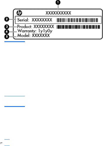
Service tag
When ordering parts or requesting information, provide the computer serial number and model description provided on the service tag, which is located on the bottom of the computer.
Item |
Description |
Function |
|
|
|
(1) |
Product name |
This is the product name affixed to the front of |
|
|
the computer. |
|
|
|
(2) |
Serial number |
This is an alphanumeric identifier that is unique to |
|
|
each product. |
|
|
|
(3) |
Part number/Product number |
This number provides specific information about the |
|
|
product's hardware components. The part number |
|
|
helps a service technician to determine what |
|
|
components and parts are needed. |
|
|
|
(4) |
Warranty period |
This number describes the duration of the warranty |
|
|
period for the computer. |
(5)Model description (select models only)
This is the alphanumeric identifier used to locate documents, drivers, and support for the computer.
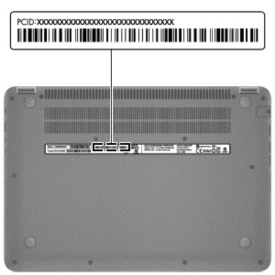
PCID label
The PCID label provides the information required to properly reset the notebook firmware (BIOS) back to factory shipped specifications when replacing the system board. The label may have a different number of characters depending on the operating system on the computer.
 NOTE: Computer details may vary from images.
Windows 8 models
6 |
Chapter 1 Product description |
Service tag and PCID label |
7 |
2 External component identification
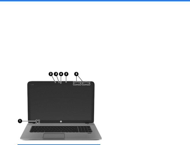
Display
Component |
Description |
|
|
|
|
(1) |
Internal display switch |
Turns off the display and initiates Sleep if the display is closed |
|
|
while the power is on. |
|
|
NOTE: The internal display switch is not visible from the |
|
|
outside of the computer. |
|
|
|
(2) |
Internal microphones (2) |
Record sound. |
|
|
|
(3) |
Webcam light |
On: The webcam is in use. |
|
|
|
8 |
Chapter 2 External component identification |
Component |
Description |
|
|
|
|
(4) |
HP TrueVision HD Webcam |
Records video and takes still photographs. |
|
|
Swipe from the right edge of the TouchPad or touch |
|
|
screen (select models only) to display the charms, tap Search, |
|
|
and then tap the search box. Type c, and then select |
|
|
CyberLink YouCam from the list of applications. |
|
|
– or – |
|
|
From the Start screen, type c, and then select |
|
|
CyberLink YouCam from the list of applications. |
|
|
|
(5) |
WLAN antennas (2)* |
Send and receive wireless signals to communicate with wireless |
|
|
local area networks (WLANs). |
*The antennas are not visible from the outside of the computer. For optimal transmission, keep the areas immediately around the antennas free from obstructions. For wireless regulatory notices, see the section of the Regulatory, Safety, and Environmental Notices that applies to your country or region. To access this guide, from the Start screen, type support, select the HP Support Assistant app, select My computer, and then select User guides.
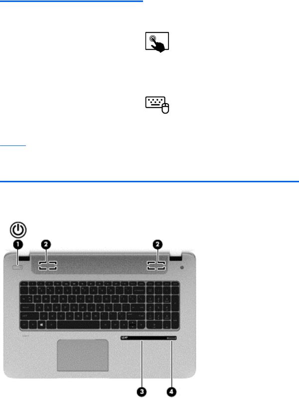
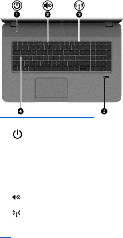
Buttons and speakers
Buttons and speakers |
9 |
Component |
|
Description |
|
|
|
(1) |
Power button |
● When the computer is off, press the button to turn on |
|
|
the tablet. |
|
|
● When the computer is on, press the button briefly to |
|
|
initiate Sleep. |
|
|
● When the computer is in the Sleep state, press the |
|
|
button briefly to exit Sleep. |
|
|
CAUTION: Pressing and holding down the power button |
|
|
will result in the loss of unsaved information. |
|
|
● If the computer has stopped responding and Microsoft® |
|
|
Windows® shutdown procedures are ineffective, press |
|
|
and hold the power button down for at least 5 seconds |
|
|
to turn off the tablet. |
|
|
Swipe from the right edge of the TouchPad or |
|
|
touch screen (select models only) to display the charms, tap |
|
|
Search, and then tap the search box. In the search box, |
|
|
type power, select Settings, and then select Power |
|
|
options. |
|
|
– or – |
|
|
To learn more about your power settings, from the |
|
|
Start screen, type p. In the search box, type power, select |
|
|
Settings, and then select Power options. |
|
|
|
(2) |
Speakers (2) |
Produce sound. |
|
|
|
(3) |
Leap Motion™ (select models only) |
Leap Motion allows you to control custom apps with your |
|
|
hands and fingers in the air. When you first turn Leap |
Motion on, follow the setup instructions to experience the interactive tutorial and create an account for Airspace™, the Leap Motion app store. Airspace is where you will launch your Leap Motion apps, and discover new apps designed specifically for 3D interaction using the speed and accuracy of Leap Motion technology.
(4)Fingerprint reader (select models only)
Allows a fingerprint logon to Windows, instead of a password logon.
10 |
Chapter 2 External component identification |
Keys
Component |
|
Description |
|
|
|
(1) |
esc key |
Reveals system information when pressed in combination |
|
|
with the fn key. |
|
|
|
(2) |
fn key |
Executes frequently used system functions when pressed in |
|
|
combination with the b key, the spacebar, or the esc key. |
|
|
|
(3) |
Windows key |
Returns you to the Start screen from an open app or the |
|
|
Windows desktop. |
|
|
NOTE: Pressing the Windows key again will return you to |
|
|
the previous screen. |
|
|
|
(4) |
Action keys |
Execute frequently used system functions. |
|
|
NOTE: On select models, the f5 action key turns the |
|
|
radiance backlight keyboard feature off or on. |
|
|
|
(5) |
num lk key |
Alternates between the navigational and numeric functions |
|
|
on the integrated numeric keypad. |
|
|
|
(6) |
Integrated numeric keypad |
When num lk has been enabled, it can be used like an |
|
|
external numeric keypad. |
|
|
|
Keys 11
Lights
Component |
|
Description |
|
|
|
|
|
(1) |
Power light |
● |
White: The computer is on. |
|
|
● |
Blinking white: The computer is in the Sleep state, which |
|
|
|
is an energy-saving mode. The computer shuts off power |
|
|
|
to the display and other unneeded components. |
|
|
● |
Off: The computer is off or in Hibernation. Hibernation |
|
|
|
is an energy-saving mode that uses the least amount of |
|
|
|
power. |
|
|
|
NOTE: For select models, the Intel® Rapid Start |
|
|
|
Technology feature is enabled at the factory. Rapid Start |
|
|
|
Technology allows your computer to resume quickly |
|
|
|
from inactivity. |
|
|
|
|
(2) |
Mute light |
● |
Amber: Computer sound is off. |
|
|
● |
Off: Computer sound is on. |
|
|
|
|
(3) |
Wireless light |
On: An integrated wireless device, such as a wireless local |
|
|
|
area network (WLAN) device and/or a Bluetooth® device, is |
|
|
|
on. |
|
NOTE: On some models, the wireless light is amber when all wireless devices are off.
12 |
Chapter 2 External component identification |
Component |
|
Description |
|
|
|
|
|
(4) |
Caps lock light |
On: Caps lock is on, which switches the keys to all capital |
|
|
|
letters. |
|
|
|
|
|
(5) |
Fingerprint reader light |
● |
White: The fingerprint authentication was successful. |
|
|
● |
Amber: The fingerprint authentication failed. |
|
|
|
|
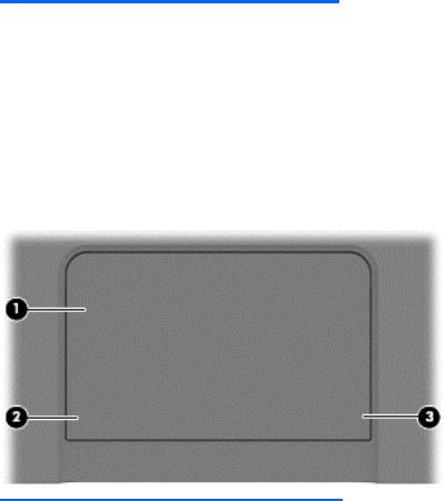
TouchPad
Component |
|
Description |
|
|
|
(1) |
TouchPad zone |
Moves the on-screen pointer and selects or activates items on |
|
|
the screen. |
|
|
NOTE: The TouchPad also supports edge-swipe gestures. |
|
|
|
(2) |
Left TouchPad button |
Functions like the left button on an external mouse. |
|
|
|
(3) |
Right TouchPad button |
Functions like the right button on an external mouse. |
|
|
|
TouchPad 13
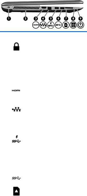
Left side
Component |
|
Description |
|
|
|
(1) |
Security cable slot |
Attaches an optional security cable to the computer. |
|
|
NOTE: The security cable is designed to act as a |
|
|
deterrent, but it may not prevent the computer from being |
|
|
mishandled or stolen. |
|
|
|
(2) |
Vents (2) |
Enable airflow to cool internal components. |
|
|
NOTE: The computer fan starts up automatically to cool |
|
|
internal components and prevent overheating. It is normal for |
|
|
the internal fan to cycle on and off during routine operation. |
|
|
|
(3) |
HDMI port |
Connects an optional video or audio device, such as a high- |
|
|
definition television, any compatible digital or audio |
|
|
component, or a high-speed HDMI device. |
|
|
|
(4) |
RJ-45 (network) jack |
Connects a network cable. |
|
|
|
|
RJ-45 (network) status light |
White: The network is connected. |
|
|
Amber: Activity is occurring on the network. |
|
|
|
(5) |
USB 3.0 charging port |
Connects an optional USB device. The USB 3.0 charging |
|
|
port can also charge select models of cell phones and MP3 |
|
|
players, even when the computer is off. |
|
|
NOTE: A USB charging port (also referred to as a USB |
|
|
powered port) allows you to charge connected USB devices. |
|
|
Standard USB ports will not charge all USB devices or will |
|
|
charge using a low current. Some USB devices require |
|
|
power and require you to use a powered port. |
|
|
|
(5) |
USB 3.0 port |
Connects optional USB 3.0 devices and provide enhanced |
|
|
USB power performance. |
|
|
|
(6) |
Memory card reader |
Reads data from and writes data to memory cards such as |
|
|
Secure Digital (SD). |
|
|
|
14 |
Chapter 2 External component identification |

Component |
|
Description |
|
|
|
|
|
(7) |
Hard drive light |
● |
Blinking white: The hard drive is being accessed. |
|
|
● |
Amber: HP 3D DriveGuard has temporarily parked the |
|
|
|
hard drive. |
|
|
|
|
(8) |
Power light |
● |
White: The computer is on. |
|
|
● |
Blinking white: The computer is in the Sleep state, |
|
|
|
which is an energy-saving mode. The computer shuts |
|
|
|
off power to the display and other unneeded |
|
|
|
components. |
|
|
● |
Off: The computer is off or in Hibernation. Hibernation |
|
|
|
is an energy-saving mode that uses the least amount of |
|
|
|
power. |
NOTE: For select models, the Intel® Rapid Start Technology feature is enabled at the factory. Rapid Start Technology allows your computer to resume quickly from inactivity..
Right side
Component |
|
Description |
|
|
|
(1) |
Audio-out (headphone) jack/Audio-in |
Connects optional powered stereo speakers, headphones, |
|
(microphone) jack |
earbuds, a headset, or a television audio cable. Also |
|
|
connects an optional headset microphone. This jack does not |
|
|
support optional microphone-only devices. |
|
|
WARNING! To reduce the risk of personal injury, adjust |
|
|
the volume before putting on headphones, earbuds, or a |
|
|
headset. For additional safety information, refer to the |
|
|
Regulatory, Safety, and Environmental Notices. To access |
|
|
this guide, from the Start screen, type support, select the |
|
|
HP Support Assistant app, select My computer, and |
|
|
then select User guides. |
|
|
NOTE: When a device is connected to the jack, the |
|
|
computer speakers are disabled. |
|
|
NOTE: Be sure that the device cable has a 4-conductor |
|
|
connector that supports both audio-out (headphone) and |
|
|
audio-in (microphone). |
|
|
|
(2) |
USB 3.0 ports (2) |
Connect optional USB 3.0 devices and provide enhanced |
|
|
USB power performance. |
|
|
|
Right side |
15 |

Component |
|
Description |
|
|
|
(3) |
Optical drive |
Reads and writes (select models only) to an optical disc. |
|
|
|
(4) |
Optical drive eject button |
Releases the optical drive disc tray |
|
|
|
(5) |
AC adapter light |
● White: The AC adapter is connected and the battery is |
|
|
charged. |
|
|
● Amber: The AC adapter is connected and the battery is |
|
|
charging. |
|
|
● Off: The computer is using DC power. |
|
|
|
(6) |
Power connector |
Connects an AC adapter. |
|
|
|
16 |
Chapter 2 External component identification |
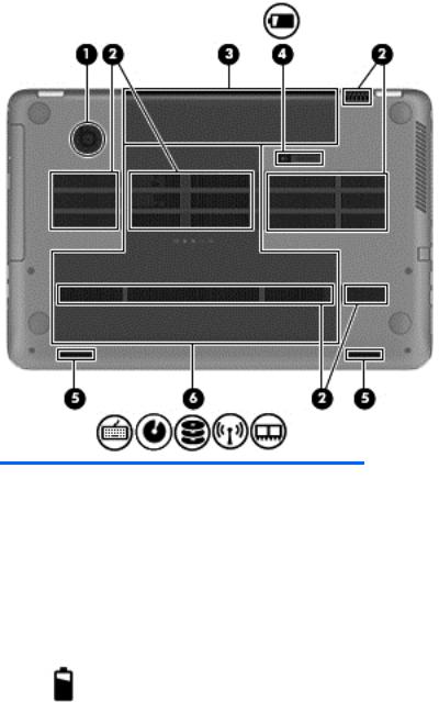
Bottom
Component |
|
Description |
|
|
|
(1) |
HP Triple Bass Reflex Subwoofer |
Provides superior bass sound. |
|
|
|
(2) |
Vents (4) |
Enable airflow to cool internal components. |
|
|
NOTE: The computer fan starts up automatically to |
|
|
cool internal components and prevent overheating. It is |
|
|
normal for the internal fan to cycle on and off during |
|
|
routine operation. |
|
|
|
(3) |
Battery bay |
Holds the battery. |
|
|
|
(4) |
Battery release latch |
Releases the battery. |
|
|
|
Bottom 17

Component |
|
Description |
|
|
|
(5) |
Speakers (2) |
Produce sound. |
|
|
|
(6) |
Service door |
Provides access to the hard drive bay, the wireless LAN |
|
|
(WLAN) module slot, and the memory module slots. |
CAUTION: To prevent an unresponsive system, replace the wireless module only with a wireless module authorized for use in the computer by the governmental agency that regulates wireless devices in your country or region. If you replace the module and then receive a warning message, remove the module to restore computer functionality, and then contact support through Help and Support. From the Start screen, type h, and then select Help and Support.
18 |
Chapter 2 External component identification |

3 Illustrated parts catalog
Computer major components


 NOTE: Details about your computer, including model, serial number, product key, and length of warranty, are on the service tag at the bottom of your computer. See Service tag and PCID label on page 6 for details.
Computer major components |
19 |

20 |
Chapter 3 Illustrated parts catalog |
Loading...