


EliteBook 2530p

HP EliteBook 2530p Notebook PC
Maintenance and Service Guide

© Copyright 2008 Hewlett-Packard
Development Company, L.P.
Bluetooth is a trademark owned by its
proprietor and used by Hewlett-Packard
Company under license. Intel and Core are
trademarks of Intel Corporation in the U.S.
and other countries. Java is a US trademark
of Sun Microsystems, Inc. Microsoft,
Windows, Windows XP, and Windows Vista
are U.S. registered trademarks of Microsoft
Corporation. SD Logo is a trademark of its
proprietor.
The information contained herein is subject
to change without notice. The only
warranties for HP products and services are
set forth in the express warranty statements
accompanying such products and services.
Nothing herein should be construed as
constituting an additional warranty. HP shall
not be liable for technical or editorial errors
or omissions contained herein.
Second Edition: October 2008
First Edition: September 2008
Document Part Number: 486606-002

Safety warning notice
WARNING! To reduce the possibility of heat-related injuries or of overheating the computer, do not
place the computer directly on your lap or obstruct the computer air vents. Use the computer only on a
hard, flat surface. Do not allow another hard surface, such as an adjoining optional printer, or a soft
surface, such as pillows or rugs or clothing, to block airflow. Also, do not allow the AC adapter to contact
the skin or a soft surface, such as pillows or rugs or clothing, during operation. The computer and the
AC adapter comply with the user-accessible surface temperature limits defined by the International
Standard for Safety of Information Technology Equipment (IEC 60950).
iii

iv Safety warning notice

Table of contents
1 Product description
2 External component identification
Top components ................................................................................................................................... 5
Pointing devices ................................................................................................................... 5
Lights ................................................................................................................................... 6
Buttons, switches, and fingerprint reader ............................................................................ 8
Keys ................................................................................................................................... 10
Display ............................................................................................................................... 11
Front components .............................................................................................................................. 12
Rear components ............................................................................................................................... 13
Right-side components ....................................................................................................................... 14
Left-side components ......................................................................................................................... 15
Bottom components ........................................................................................................................... 17
Wireless antennae (select models only) ............................................................................................. 19
3 Illustrated parts catalog
Serial number location ........................................................................................................................ 20
Computer major components ............................................................................................................. 22
Display components ........................................................................................................................... 27
Mass storage ...................................................................................................................................... 29
Plastics Kit .......................................................................................................................................... 31
Miscellaneous parts ............................................................................................................................ 32
Sequential part number listing ............................................................................................................ 33
4 Removal and replacement procedures
Preliminary replacement requirements ............................................................................................... 37
Tools required .................................................................................................................... 37
Service considerations ....................................................................................................... 37
Plastic parts ....................................................................................................... 37
Cables and connectors ..................................................................................... 38
Drive handling ................................................................................................... 38
Grounding guidelines ......................................................................................................... 39
v

Electrostatic discharge damage ........................................................................ 39
Packaging and transporting guidelines ............................................. 40
Workstation guidelines ..................................................................... 40
Equipment guidelines ....................................................................... 41
Unknown user password ................................................................................................... 42
Component replacement procedures ................................................................................................. 43
Service tag ......................................................................................................................... 44
Computer feet .................................................................................................................... 45
Battery ............................................................................................................................... 46
SIM .................................................................................................................................... 47
Bluetooth module ............................................................................................................... 48
Expansion memory module ............................................................................................... 50
WLAN module .................................................................................................................... 52
Primary hard drive ............................................................................................................. 55
WWAN module .................................................................................................................. 58
Optical drive ....................................................................................................................... 60
Switch cover and keyboard ................................................................................................ 62
LED board .......................................................................................................................... 66
RTC battery ....................................................................................................................... 67
Secondary hard drive ......................................................................................................... 68
Primary memory module .................................................................................................... 73
Display assembly ............................................................................................................... 74
Top cover ........................................................................................................................... 80
Speaker ............................................................................................................................. 83
System board ..................................................................................................................... 84
ExpressCard assembly ...................................................................................................... 86
Modem module .................................................................................................................. 88
Fan ..................................................................................................................................... 90
Heat sink ............................................................................................................................ 92
5 Computer Setup
Starting Computer Setup .................................................................................................................... 94
Using Computer Setup ....................................................................................................................... 95
Computer Setup menus ..................................................................................................................... 97
6 Specifications
Computer specifications ................................................................................................................... 103
vi
Navigating and selecting in Computer Setup ..................................................................... 95
Restoring factory settings in Computer Setup ................................................................... 96
File menu ........................................................................................................................... 97
Security menu .................................................................................................................... 98
Diagnostics menu .............................................................................................................. 99
System Configuration menu ............................................................................................ 100

12.1-inch, WXGA display specifications ........................................................................................... 104
Hard drive specifications .................................................................................................................. 105
DVD-ROM Drive specifications ........................................................................................................ 106
DVD±RW and CD-RW SuperMulti Double-Layer Combo Drive specifications ................................ 107
System DMA specifications .............................................................................................................. 108
System interrupt specifications ......................................................................................................... 109
System I/O address specifications ................................................................................................... 110
System memory map specifications ................................................................................................. 112
7 Screw listing
Phillips PM 2.0×4.0 screw ................................................................................................................ 114
Torx T8M2.0×5.0 screw ................................................................................................................... 118
Torx T8M2.0×6.0 captive screw ....................................................................................................... 121
Phillips PM2.5×4.0 screw ................................................................................................................. 122
Phillips PM2.5×6.0 captive screw ..................................................................................................... 123
Phillips PM2.5×6.0 screw ................................................................................................................. 124
Torx T8M2.5×6.0 screw ................................................................................................................... 126
Torx T8M2.5×9.0 captive screw ....................................................................................................... 128
Phillips PM2.5×11.0 captive screw ................................................................................................... 129
8 Backup and recovery
Backup and recovery in Windows Vista ........................................................................................... 130
Overview .......................................................................................................................... 130
Backing up your information ............................................................................................ 131
Performing a recovery ..................................................................................................... 132
Backup and recovery in Windows XP .............................................................................................. 134
Overview .......................................................................................................................... 134
Backing up your information ............................................................................................ 135
Performing a recovery ..................................................................................................... 136
9 Connector pin assignments
Audio-in (microphone) ...................................................................................................................... 137
Audio-out (headphone) ..................................................................................................................... 138
External monitor ............................................................................................................................... 139
IEEE 1394 (FireWire) ....................................................................................................................... 140
RJ-11 (modem) ................................................................................................................................ 141
RJ-45 (network) ................................................................................................................................ 142
Universal Serial Bus ......................................................................................................................... 143
Using the Windows recovery tools .................................................................. 132
Using f11 ......................................................................................................... 133
Using a Windows Vista operating system DVD (purchased separately) ........ 133
Recovering your information ........................................................................... 136
Recovering the operating system and programs ............................................ 136
vii

10 Power cord set requirements
Requirements for all countries and regions ...................................................................................... 144
Requirements for specific countries and regions ............................................................................. 145
11 Recycling
Battery .............................................................................................................................................. 146
Display .............................................................................................................................................. 147
Index ................................................................................................................................................................. 152
viii

1 Product description
Category Description
Product Name HP EliteBook 2530p Notebook PC
Processors Intel® LV Core™2 Duo, soldered uFBGA
SL9600 2.13-GHz, 1066MHZ front side bus (FSB) with 6-MB cache
●
SL9400 1.86-GHz, 1066MHz FSB with 6-MB cache
●
SL9300 1.6-GHz, 1066MHz FSB with 6-MB cache
●
Intel ULV Core2 Duo, soldered uFBGA
SU9400, 1.4-GHz, 800 MHz, FSB with 3-MB cache
●
SU9300, 1.2-GHz, 800MHz FSB with 3-MB cache
●
Chipset Mobile Intel Express GS45
ICH9m-SFF-enhanced
Graphics Intel Universal Memory Architecture (UMA) graphics subsystem integrated with up to 384-MB
shared system memory
Panels 12.1-inch WXGA display assembly (1280 × 800) with Antiglare, includes 2 wireless local area
network (WLAN) antennae, and supports privacy filter
Memory Two customer-accessible/upgradable memory module slots
Supports up to 8 GB of system RAM
800-MHz, DDR2
Supports the following configurations:
8192-MB total system memory (4096 × 2)
●
6144-MB total system memory (4096 + 2048)
●
5120-MB total system memory (4096 + 1024)
●
4096-MB total system memory (4096 × 1)
●
4096-MB total system memory (2048 × 2)
●
3072-MB total system memory (2048 + 1024)
●
2048-MB total system memory (2048 × 1)
●
2048-MB total system memory (1024 × 2)
●
1024-MB total system memory (1024 × 1)
●
1

Category Description
Hard drives Customer-accessible
Supports the following SATA primary drives:
NOTE: The 4.57-cm (1.80-inch) primary hard drive must be installed in the hard drive bay.
Installation of this drive in the optical drive bay is not supported.
160-GB, 5400-rpm
●
120-GB, 5400-rpm
●
80-GB, 5400-rpm
●
Supports the following primary solid-state drive:
80-GB, Intel
●
Supports the following SATA secondary drives installed in the optical drive bay:
NOTE: The 6.35-cm (2.50-inch) secondary hard drive must be installed in the optical drive bay.
Installation of this drive in the hard drive bay is not supported. (This option is not available when
the optical drive is installed.)
320-GB, 7200-rpm
●
250-GB, 5400-rpm
●
160-GB, 7200-rpm
●
160-GB, 5400-rpm
●
120-GB, 5400-rpm
●
Optical drives Fixed (removal of 1 screw required)
NOTE: This option is not available with a secondary hard drive installed as primary storage.
Customer-accessible
Serial ATA (SATA)
9.5-mm tray load
Supports the following drive options:
DVD-ROM Drive
●
DVD±RW and CD-RW SuperMulti Double-Layer Combo Drive
●
No optical drive, with optical drive space-saver
●
Diskette drive Supports external USB diskette drive only
Supports boot from external USB diskette drive
Audio HD audio - ADI1984A
Integrated single speaker, no speaker branding
Integrated dual-array microphone
Webcam Optional 2.1-megapixel webcam with support for a business card reader
Modem 56K V.92 data/fax modem
Ethernet Integrated Gigabit 10/100/1000 local access network (LAN)
2 Chapter 1 Product description

Category Description
S4/S5 wake on LAN on AC power
NIC power-down technology
Wireless LAN Integrated WLAN options by way of mini-slot which supports WLAN only:
Support for 2 dual-band 2.4-/5.0-GHz WLAN antennae cabled to mini-slot
Support for the following WLAN options:
802.11a/b/g with Intel Active Management Technology (iAMT) support
●
802.11a/b/g/n with iAMT support
●
802.11a/b/g/draft-n
●
802.11b/g
●
no-WLAN option
●
Integrated WWAN options by way of mini-slot which supports WWAN only:
Support for 2 five-band WWAN antennae cabled to mini-slot
SIM is user-accessible behind battery
Supports the following WWAN options:
HP un2400 Mobile Broadband Module
●
WWAN aftermarket option
●
Integrated WPAN option by way of mini-slot which supports WPAN only:
Supports no-wireless PAN option
Blueflame Bluetooth® module
External media card SD Card Reader supporting Secure Digital (SD) Memory Card and MultiMediaCard (MMC)
Ports Audio-in (stereo microphone)
Audio-out (stereo headphone)
Docking
RJ-11 (modem)
RJ-45 (Ethernet, includes link and activity lights)
USB (2 ports on models with an optical drive installed, 3 ports on models without an optical drive
installed)
VGA (Dsub 15-pin) supporting 1600 × 1200 external resolution at 75-GHz (hot plug/unplug with
3-pin AC power via the HP Smart AC Adapter
Docking HP 2400/2500 Series Docking Station
Keyboard/pointing
devices
auto-detect)
Full–size 4.5-mm×19.05-mm keyboard with embedded numeric keypad
Pointing stick with 2 pointing stick buttons
TouchPad with 2 TouchPad buttons and vertical scrolling zone
3

Category Description
Spill-resistant keyboard
Windows Vista® Start button
Durable key caps
Power requirements 65-W Smart AC adapter with localized cable plug support (3-wire plug with ground pin)
9-cell, 83.0-Wh Li-ion battery with fuel gauge
6-cell, 55.0-Wh Li-ion battery with fuel gauge
3-cell, 31.0-Wh Li-ion battery
Security Supports Kensington security lock
Supports integrated USB-based fingerprint reader
Operating system Preinstalled:
Vista Home Basic (32-bit)
Vista Business (32-bit)
Vista Ultimate (32-bit)
FreeDOS
Serviceability End-user replaceable parts:
AC adapter and power cord
Battery (system)
SIM
Bluetooth module
Memory module
WLAN module
WWAN module
Optical drive
RTC battery
Switch cover
Keyboard
Primary hard drive
Primary hard drive (solid-state)
NOTE: The 4.57-cm (1.80-inch) primary hard drive must be installed in the hard drive bay.
Installation of this drive in the optical drive bay is not supported.
Secondary hard drive
NOTE: The 6.35-cm (2.50-inch) secondary hard drive must be installed in the optical drive bay.
Installation of this drive in the hard drive bay is not supported. (This option is not available when
the optical drive is installed.)
4 Chapter 1 Product description
2 External component identification
Top components
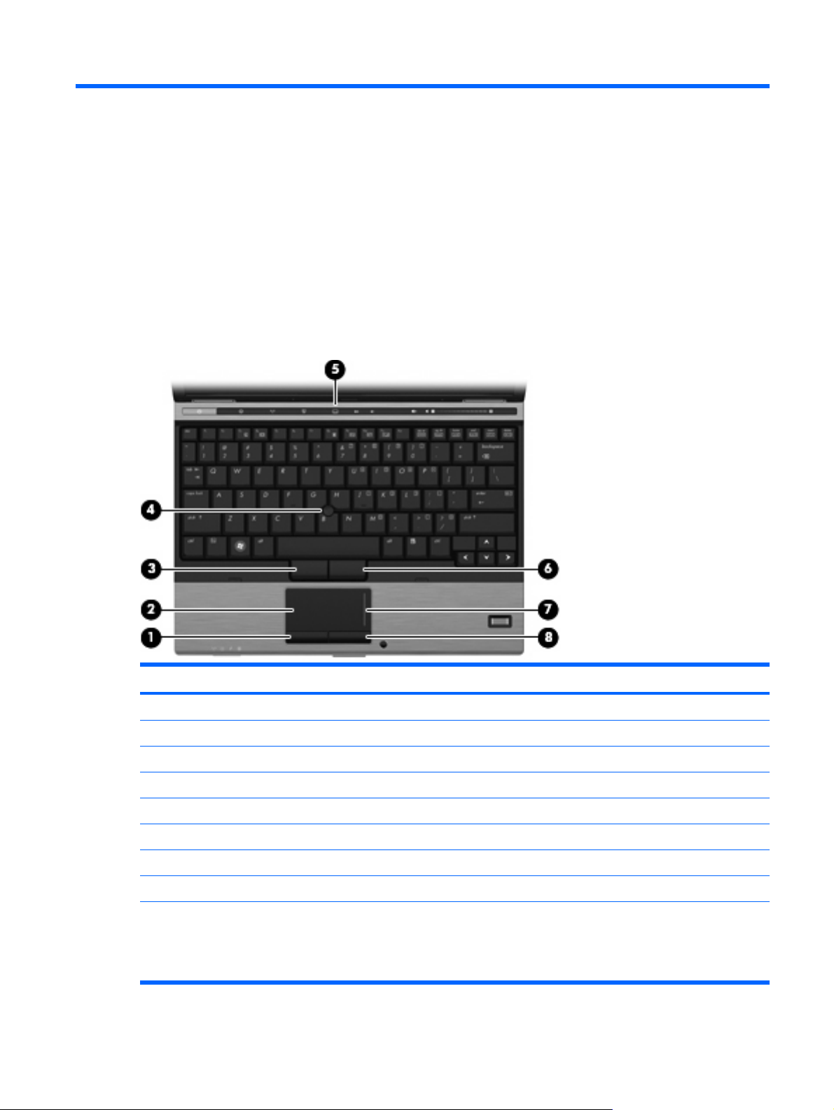
Pointing devices
Component Description
(1) Left TouchPad button* Functions like the left button on an external mouse.
(2) TouchPad* Moves the pointer and selects or activates items on the screen.
(3) Left pointing stick button* Functions like the left button on an external mouse.
(4) Pointing stick* Moves the pointer and selects or activates items on the screen.
(5) TouchPad on/off button Turns the TouchPad on and off.
(6) Right pointing stick button* Functions like the right button on an external mouse.
(7) TouchPad scroll zone Scrolls up or down.
(8) Right TouchPad button* Functions like the right button on an external mouse.
*This table describes factory settings. To view or change pointing device preferences:
For Windows Vista, select Start > Control Panel > Hardware and Sound > Mouse.
●
For Windows® XP, select Start > Control Panel > Printers and Other Hardware > Mouse.
●
Top components 5
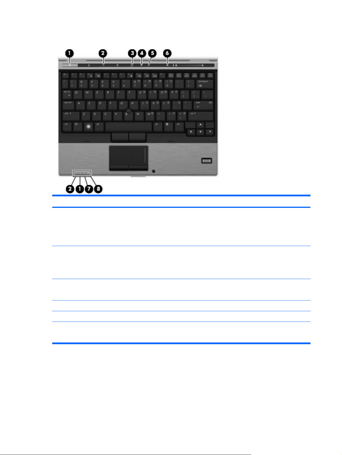
Lights
Component Description
(1) Power lights (2)*
(2) Wireless lights (2)†
(3) TouchPad on/off light
(4) Caps lock light On: Caps lock is on.
(5) Num lock light On: Num lock is on or the embedded numeric keypad is enabled.
(6) Volume mute light
On: The computer is on.
●
Blinking: The computer is in the Sleep state (Windows Vista)
●
or Standby (Windows XP).
Off: The computer is off or in Hibernation.
●
Blue: An integrated wireless device, such as a wireless local
●
area network (WLAN) device, the HP Mobile Broadband
Module, and/or a Bluetooth device, is on.
Amber: All wireless devices are off.
●
Turquoise: TouchPad is on.
●
Amber: TouchPad is off.
●
Turquoise: Speaker sound is on.
●
Amber: Speaker sound is off.
●
6 Chapter 2 External component identification

Component Description
(7) Battery light
(8) Drive light
*The 2 power lights display the same information. The light on the power button is visible only when the computer is open. The
power light on the front of the computer is visible whether the computer is open or closed.
†The 2 wireless lights display the same information. The light on the wireless button is visible only when the computer is open.
The wireless light on the front of the computer is visible whether the computer is open or closed.
Amber: A battery is charging.
●
Turquoise: A battery is close to full charge capacity.
●
Blinking amber: A battery that is the only available power
●
source has reached a low battery level. When the battery
reaches a critical battery level, the battery light begins blinking
rapidly.
Off: If the computer is plugged into an external power source,
●
the light turns off when all batteries in the computer are fully
charged. If the computer is not plugged into an external power
source, the light stays off until the battery reaches a low
battery level.
Blinking turquoise: The hard drive or optical drive is being
●
accessed.
Amber: HP 3D DriveGuard has temporarily parked the internal
●
hard drive.
Top components 7
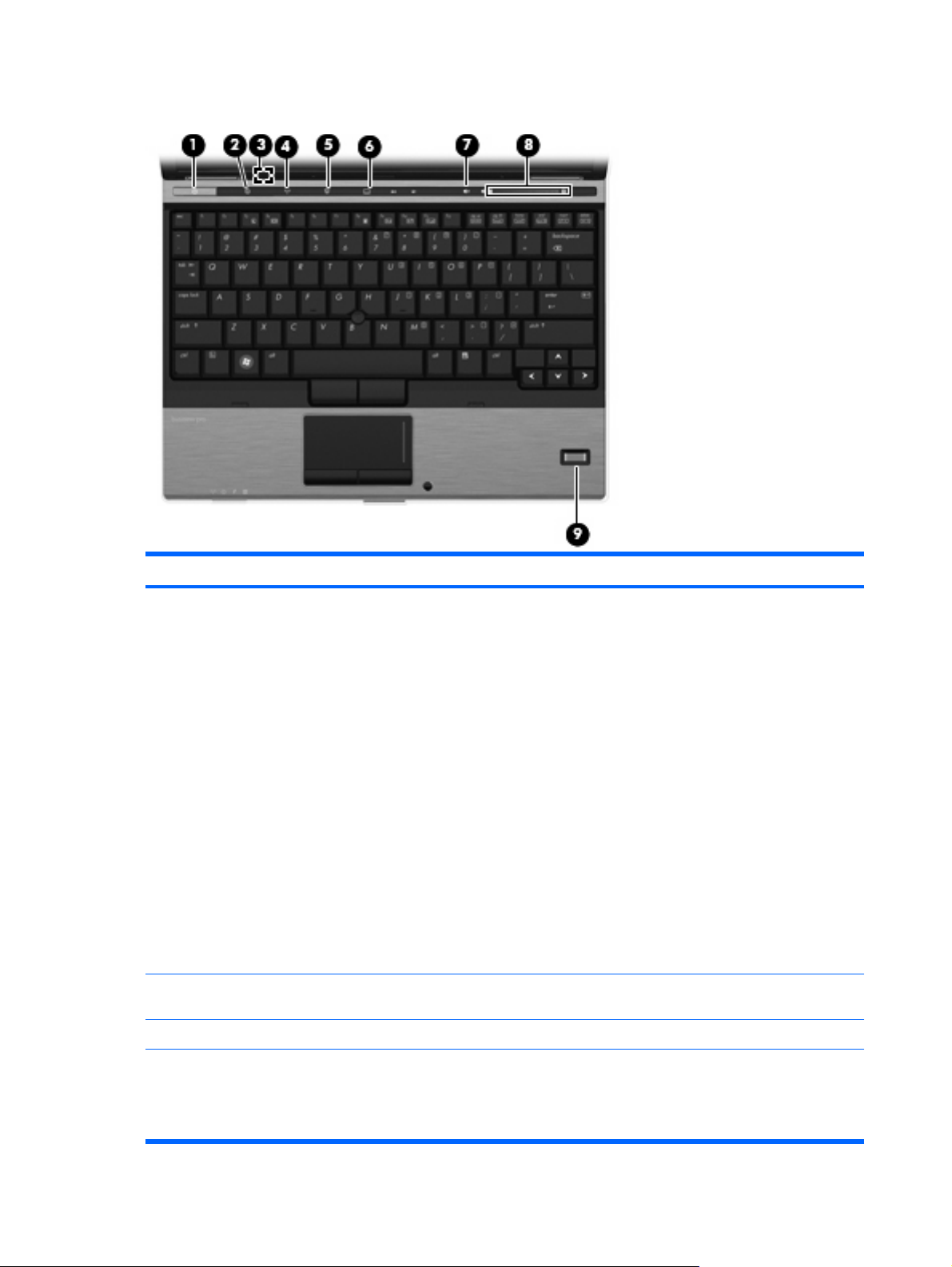
Buttons, switches, and fingerprint reader
Component Description
(1) Power button
(2) Info button Launches Info Center, which enables you to open various software
(3) Internal display switch Turns off the display if the display is closed while the power is on.
(4) Wireless button Turns the wireless feature on or off but does not establish a
When the computer is off, press the button to turn on the
●
computer.
When the computer is on, press the button to shut down the
●
computer.
When the computer is in the Sleep state (Windows Vista) or
●
Standby (Windows XP), press the button briefly to exit the
Sleep state or Standby.
When the computer is in Hibernation, press the button briefly
●
to exit Hibernation.
If the computer has stopped responding and Windows® shutdown
procedures are ineffective, press and hold the power button for at
least 5 seconds to turn off the computer.
To learn more about your power settings:
For Windows Vista, select Start > Control Panel > System
●
and Maintenance > Power Options.
For Windows XP, select Start > Control Panel >
●
Performance and Maintenance > Power Options.
solutions.
wireless connection.
8 Chapter 2 External component identification
NOTE: A wireless network must be set up in order to establish a
wireless connection.

Component Description
(5) Presentation button Starts the presentation feature.
(6) TouchPad on/off button Turns the TouchPad on or off.
(7) Volume mute button Mutes and restores speaker sound.
(8) Volume scroll zone Adjusts speaker volume. Slide your finger to the left to decrease
volume and to the right to increase volume. You can also press and
hold the minus (–) sign to decrease volume, or press and hold the
plus (+) sign to increase volume.
(9) Fingerprint reader Allows a fingerprint logon to Windows, instead of a password logon.
Top components 9
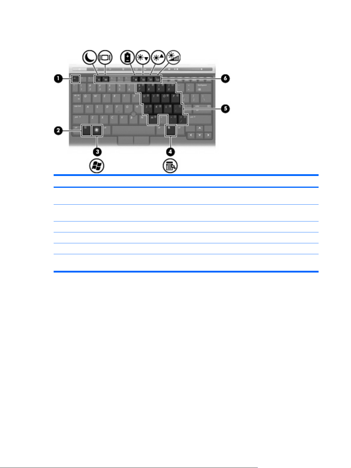
Keys
Component Description
(1) esc key Displays system information when pressed in combination with
the fn key.
(2) fn key Executes frequently used system functions when pressed in
(3) Windows logo key Displays the Windows Start menu.
(4) Windows applications key Displays a shortcut menu for items beneath the pointer.
(5) Embedded numeric keypad keys Can be used like the keys on an external numeric keypad.
(6) Function keys Execute frequently used system functions when pressed in
combination with a function key or the esc key.
combination with the fn key.
10 Chapter 2 External component identification
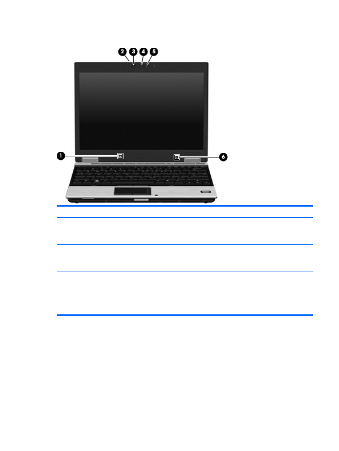
Display
Component Description
(1) Ambient light sensor Automatically adjusts the display brightness based on the lighting
conditions in your environment.
(2) Webcam light (select models only) On: The integrated camera is in use.
(3) Webcam (select models only) Records audio and video and captures still photographs.
(4) Keyboard light Illuminates the keyboard in low-light conditions when the keyboard
(5) Keyboard light button Opens and turns on the keyboard light.
(6) Internal microphone Records sound.
light button is pressed.
NOTE: The internal microphone makes use of dual array
technology, which provides speech enhancement and suppresses
surrounding noises.
Top components 11

Front components
Component Description
(1) Wireless light
(2) Power light
(3) Battery light
(4) Drive light
Blue: An integrated wireless device, such as a wireless local
●
area network (WLAN) device, the HP Mobile Broadband
Module, and/or a Bluetooth device, is on.
Amber: All wireless devices are off.
●
On: The computer is on.
●
Blinking: The computer is in the Sleep state (Windows Vista)
●
or Standby (Windows XP).
Off: The computer is off or in Hibernation.
●
Amber: A battery is charging.
●
Turquoise: A battery is close to full charge capacity.
●
Blinking amber: A battery that is the only available power
●
source has reached a low battery level. When the battery
reaches a critical battery level, the battery light begins
blinking rapidly.
Off: If the computer is plugged into an external power source,
●
the light turns off when all batteries in the computer are fully
charged. If the computer is not plugged into an external power
source, the light stays off until the battery reaches a low
battery level.
Turquoise: The hard drive or optical drive is being accessed.
●
Amber: HP 3D DriveGuard has temporarily parked the
●
internal hard drive.
(5) Business card slot Holds a business card in position so that the webcam can capture
(6) Display release button Opens the computer.
12 Chapter 2 External component identification
the information on the card.

Rear components
Component Description
(1) RJ-45 (network) jack Connects a network cable.
(2) Security cable slot Attaches an optional security cable to the computer.
NOTE: The security cable is designed to act as a deterrent, but
it may not prevent the computer from being mishandled or stolen.
Rear components 13
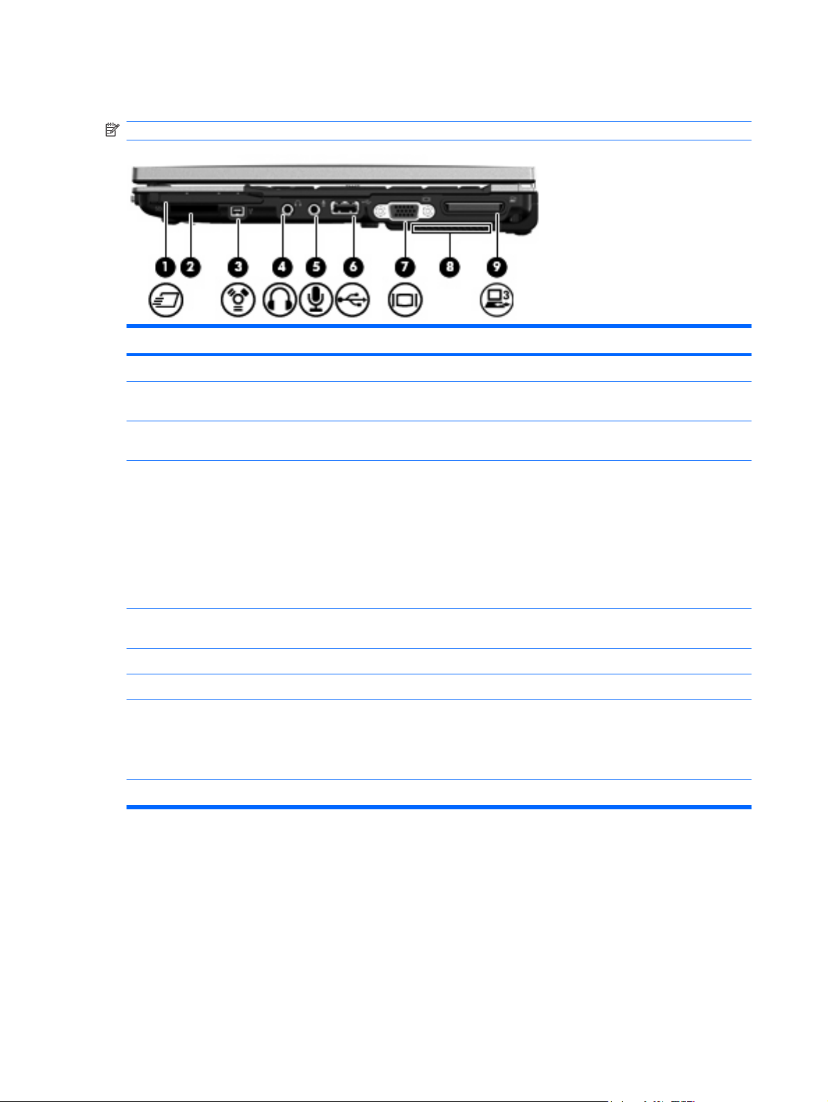
Right-side components
NOTE: Refer to the illustration that most closely matches your computer.
Component Description
(1) ExpressCard slot Supports optional ExpressCards.
(2) SD Card Reader Supports the Secure Digital (SD) Memory Card and
(3) 1394 port Connects an optional IEEE 1394 or 1394a device, such as a
(4) Audio-out (headphone) jack Produces sound when connected to optional powered stereo
MultiMediaCard (MMC) optional digital card formats.
camcorder.
speakers, headphones, ear buds, a headset, or television audio.
WARNING! To reduce the risk of personal injury, adjust the
volume before putting on headphones, earbuds, or a headset. For
additional safety information, refer to the Regulatory, Safety and
Environmental Notices.
NOTE: When a device is connected to the headphone jack, the
computer speakers are disabled.
(5) Audio-in (microphone) jack Connects an optional computer headset microphone, stereo array
microphone, or monaural microphone.
(6) USB port Connects an optional USB device.
(7) External monitor port Connects an external VGA monitor or projector.
(8) Vent Enables airflow to cool internal components.
NOTE: The computer fan starts up automatically to cool internal
components and prevent overheating. It is normal for the internal
fan to cycle on and off during routine operation.
(9) Expansion port 3 Connects an optional docking device.
14 Chapter 2 External component identification
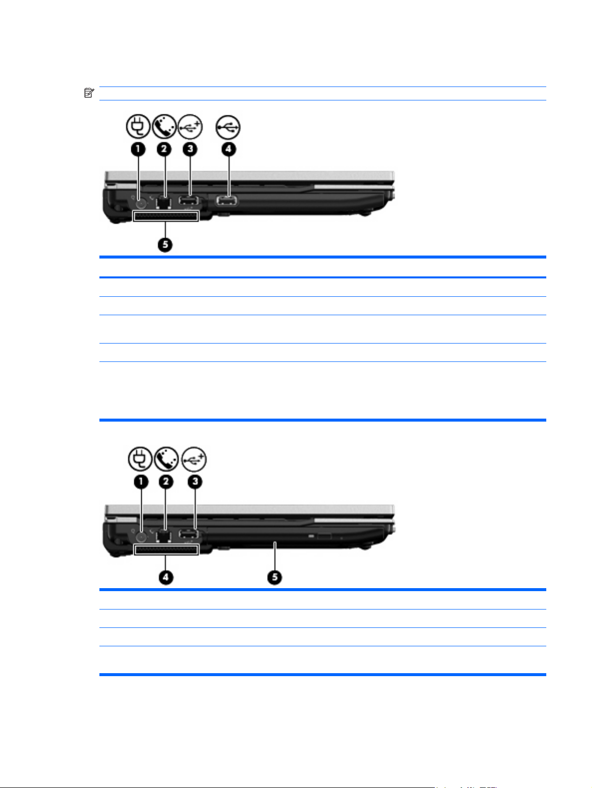
Left-side components
NOTE: Refer to the illustration that most closely matches your computer.
Component Description
(1) Power connector Connects an AC adapter.
(2) RJ-11 (modem) jack Connects a modem cable.
(3) Powered USB port Provides power to an external device if used with a powered USB
(4) USB port Connects an optional USB device.
cable.
(5) Vent Enables airflow to cool internal components.
NOTE: The computer fan starts up automatically to cool internal
components and prevent overheating. It is normal for the internal
fan to cycle on and off during routine operation.
Component Description
(1) Power connector Connects an AC adapter.
(2) RJ-11 (modem) jack Connects a modem cable.
(3) Powered USB port Provides power to an external device if used with a powered USB
cable.
Left-side components 15

(4) Vent Enables airflow to cool internal components.
NOTE: The computer fan starts up automatically to cool internal
components and prevent overheating. It is normal for the internal
fan to cycle on and off during routine operation.
(5) Optical drive Reads and writes to an optical disc.
16 Chapter 2 External component identification
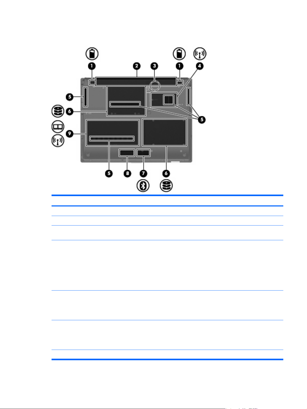
Bottom components
Component Description
(1) Battery release latches (2) Release the battery from the battery bay.
(2) Battery bay Holds the battery.
(3) SIM slot (select models only) Contains a wireless subscriber identity module (SIM). The SIM slot
is located inside the battery bay.
(4) Broadband wireless module compartment Contains an HP Mobile Broadband Module (select models only).
CAUTION: To prevent an unresponsive system, replace the
wireless module only with a wireless module authorized for use in
the computer by the governmental agency that regulates wireless
devices in your country or region. If you replace the module and
then receive a warning message, remove the module to restore
computer functionality, and then contact technical support through
Help and Support.
(5) Vents (5) Enable airflow to cool internal components.
NOTE: The computer fan starts up automatically to cool internal
components and prevent overheating. It is normal for the internal
fan to cycle on and off during routine operation.
(6) Hard drive bay Holds the hard drive.
NOTE: The 4.57-cm (1.80-inch) primary hard drive must be
installed in the hard drive bay. Installation of this drive in the optical
drive bay is not supported.
(7) Bluetooth compartment Contains a Bluetooth device.
Bottom components 17

Component Description
(8) Speaker Produces sound.
(9) Memory module compartment Contains an expansion memory module slot and a WLAN module
(select models only).
NOTE: To prevent an unresponsive system, replace the wireless
module only with a wireless module authorized for use in the
computer by the governmental agency that regulates wireless
devices in your country or region. If you replace the module and
then receive a warning message, remove the module to restore
computer functionality, and then contact technical support through
Help and Support.
18 Chapter 2 External component identification
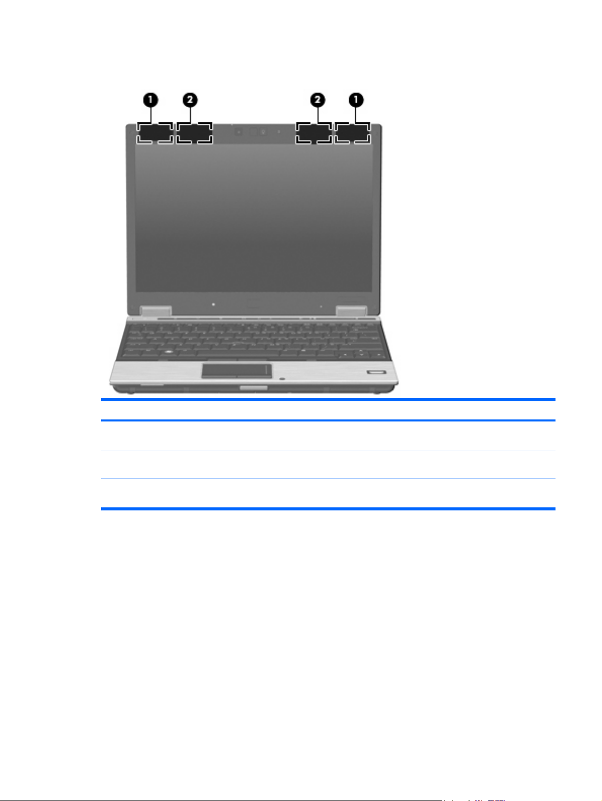
Wireless antennae (select models only)
Component Description
(1) WLAN antennae (2)* Send and receive wireless signals to communicate with wireless
(2) WWAN antennae (2)* Send and receive wireless signals to communicate with wireless
*The antennae are not visible from the outside of the computer. For optimal transmission, keep the areas immediately around
the antennae free from obstructions.
local area networks (WLAN).
wide-area networks (WWAN).
To see wireless regulatory notices, refer to the section of the Regulatory, Safety and Environmental
Notices that applies to your country or region. These notices are located in Help and Support.
Wireless antennae (select models only) 19

3 Illustrated parts catalog
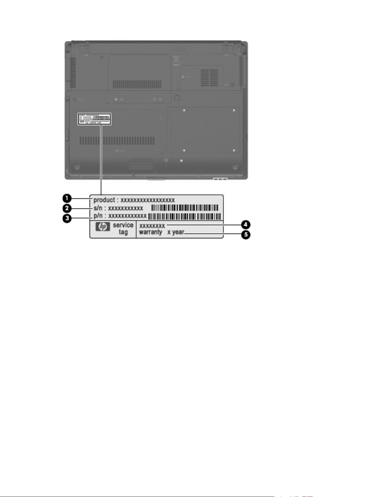
Serial number location
The service tag, affixed to the bottom of the computer, provides information that may be needed when
troubleshooting system problems. The service tag provides the following information:
(1) Product name: This is the product name affixed to the front of the computer.
(2) Serial number (s/n): This is an alphanumeric identifier that is unique to each product.
(3) Part number/Product number (p/n): This number provides specific information about the product's
hardware components. The part number helps a service technician to determine what components and
parts are needed.
(4) Model description: This is the number used to locate documents, drivers, and support for the
computer.
(5) Warranty period: This number describes the duration of the warranty period for the computer.
When ordering parts or requesting information, provide the computer serial number and model
description provided on the service tag.
20 Chapter 3 Illustrated parts catalog
Serial number location 21
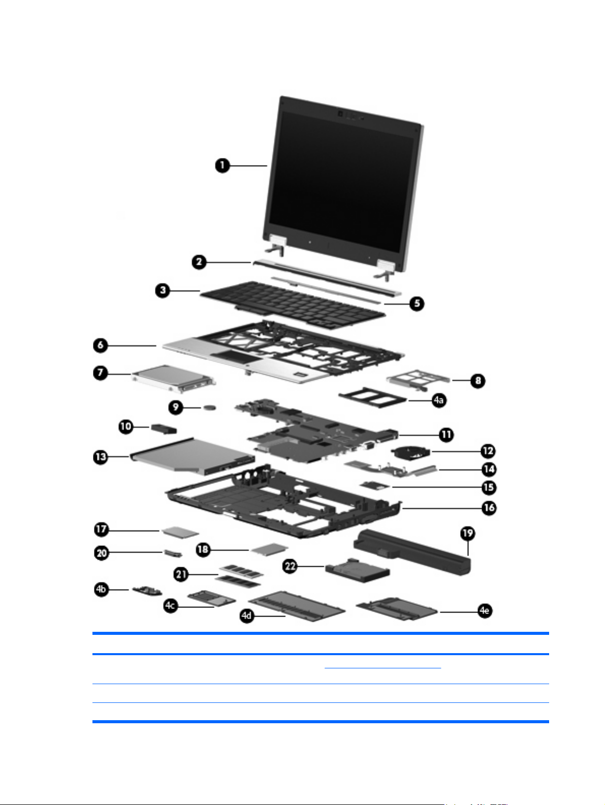
Computer major components
Item Description Spare part number
(1) 12.1-inch, WXGA AntiGlare display assembly (See Display components on page 27 for
display assembly component spare part number information.)
With webcam 492576-001
Without webcam 492575-001
22 Chapter 3 Illustrated parts catalog
 Loading...