


 Loading...
HP Designjet L25500 Printer series
Service manual
For HP Internal Use Only Warranty
©Copyright Hewlett-Packard Company 2009
This document contains proprietary information that is protected by copyright. All rights are reserved. No part of this document may be photocopied, reproduced, or translated to another language without the prior written consent of Hewlett-Packard Company.
1st Edition, November 30th 2009
Customer Assurance
Customer Experience Section
Large Format Printing Division
Hewlett-Packard Espanola, S.A.
Avda. Graells, 501
08190 Sant Cugat del Valles Spain
The information contained in this document is subject to change without notice.
Hewlett-Packard makes no warranty of any kind with regard to this material, including, but not limited to, the implied warranties of merchantability and fitness for a particular purpose.
Hewlett-Packard shall not be liable for errors contained herein or for incidental or consequential damages in connection with the furnishing, performance, or use of this material.
WARNING
The procedures described in this manual are to be performed by HP-qualified service personnel only.
Electrical Shock Hazard
Serious shock hazard leading to death or injury may result if you do not take the following precautions:
-Ensure that the ac power outlet (mains) has a protective earth (ground) terminal.
-Disconnect the Printer from the power source prior to performing any maintenance.
-Prevent water or any other liquids from running onto electrical components or circuits, or through openings in the enclosure.
Electrostatic Discharge
Refer to the beginning of Chapter 4of this manual, for precautions you should take to prevent damage to the Printer circuits from electrostatic discharge.
Safety Symbols
General definitions of safety symbols are given immediately after the table of contents.
WARNING
The Warning symbol calls attention to a procedure, practice, or the like, which, if not correctly performed or adhered to, could result in personal injury. Do not proceed beyond a Warning symbol until the indicated conditions are fully understood and met.
CAUTION
The Caution symbol calls attention to an operating procedure, practice, or the like, which, if not correctly performed or adhered to, could result in damage to or destruction of part or all of the product. Do not proceed beyond a Caution symbol until the indicated conditions are fully understood and met.
HP Designjet L25500 Printer series
Service manual
Table of Contents
Printer System 1-1
Troubleshooting 2-35
System Error Codes 3-73
Service Test, Utilities and Calibrations 4-117
Print Quality 5-227
Ink Supplies 6-247
Service Parts and Diagrams 7-261
Removal and Installation 8-301
Preventive Maintenance 9-599
Repacking the Printer 10-607
Safety 11-625
Using this Manual
Purpose
This Service Manual contains information necessary to test, calibrate and service:
•HP Designjet L25500 42-inch Printer (Model CH955A)
•HP Designjet L25500 60-inch Printer (Model CH956A)
For information about using these printers, refer to the corresponding User Guide or Maintenance and Troubleshooting Guide.
Chapters
1 Printer Systems
Use this chapter as a reference for technical information about the subsystems, components and how they work together
Of particular importance are the diagrams included for each subsystem of the printer. They can be useful for both troubleshooting and disassembly.
2 Troubleshooting
Whenever a printer is not functioning correctly due to a fault, use the Troubleshooting chapter for step-by- step diagnosis until you arrive at the solution, which may include replacing a part.
Troubleshooting always begins with one of those two problems, so when you enter the chapter, navigate to the proper section and find the troubleshooting steps for the problem you have found.
This chapter does not cover the procedures for the diagnostic tests you must perform while troubleshooting, or the replacement procedures you must complete to fix the problem.
3 System Error Codes
This chapter contains the system error codes which are displayed on the Front Panel and EWS. Each system error code shown in the chapter has a brief description and the steps required to solve the error.
Most of the troubleshooting steps involve performing a test or a calibration, which can be found in the following chapter, before replacing any part that you suspect of causing the system error code, always perform, the test or calibration.
4 Tests, Utilities, and Calibrations
Use this chapter whenever you need to perform a diagnostic test, service utility, or service calibration. This chapter is meant to provide procedures and relevant information, not troubleshooting information. For troubleshooting information, navigate to the Troubleshooting chapter.
These procedures are described in full, so that you know any relevant values for the test, as well as information about what the printer is actually doing during the test.
The goal of diagnostic tests is to locate the root cause of the problem and the corresponding system error code or message that will provide you with logical steps to resolution.
Some diagnostic tests or calibrations must be performed after removing a component.
5 Print Quality (IQ Troubleshooting)
This chapter describes the image quality diagnostic procedures. Further troubleshooting information based on the symptom of the issue can be found in the customer document Maintenance and Troubleshooting Guide.
6 Ink Supplies Troubleshooting
In this chapter we describe the components of the ink supply system.
7 Service Parts
The purpose of this chapter is to detail all of the available service parts of the printer. This information is presented in tables, organized by subsystem, and includes the following:
•Official service part names
•Part numbers
•Graphics of the service parts
Use this chapter whenever you need to order a service part.
8 Removal and Installation
The purpose of the Removal and Installation chapter is to provide procedures for removing and installing service parts. Each service part has a removal procedure detailed in this chapter, and installation procedures and notes are included as needed.
Useful information like access notes and screw types (head sizes) are provided to help you work efficiently.
Whenever you remove or replace a component, check the Service Calibration Matrix at the beginning of the chapter, which tells you the tests, utilities, and calibrations that must be performed after removing or replacing a component, and in what order.
9 Preventive Maintenance
Maintenance alerts are displayed on the Front Panel and Embedded Web Server whenever maintenance is required. While most of these alerts can be resolved by the customer, some require a service engineer.
Use the preventive maintenance chapter whenever you need to perform a preventive maintenance procedure due to an alert the customer receives from the Front Panel or Embedded Web Server, or to get reference information on life counters and maintenance that must be performed by the customer.
10 Repacking Instructions
The printer is large and depending on the scenario, will require special actions in order to move it. This chapter covers the four primary moving scenarios:
•Within the same site, over flat ground
•Within the same site, over ramps or stairs (the printer must be lifted)
•To a different site, with no possibility of freezing
•To a different site, with possibility of freezing (the ink must be removed, as it is water based and can freeze).
11 Safety
This is an industrial printer with high voltages, and it can be hazardous to service the printer. The safety chapter covers all the guidelines and checks you need to perform in order to service the printer.
Readership
The primary readers of the this service manual are HP Service Engineers, although secondary readership may include resellers. All procedures must be performed by HP Service Engineers or Authorized Service Delivery Partner, except for those procedures clearly marked otherwise.
Conventions
References
Any time you are referred to another part of the manual, you will see that the text is underlined and colored green. If you are viewing the document in the form of a PDF, you can click on one of these references to go directly to the heading and page where the content is located.

1 Printer systems
Printer Systems
• |
Electrical system ..................................................................................................... |
2 |
• |
Substrate path ...................................................................................................... |
11 |
• Ink Delivery System (IDS) ....................................................................................... |
17 |
|
• Scan Axis and Carriage........................................................................................ |
19 |
|
• Service Station and Waste management ................................................................. |
22 |
|
• |
Heating system .................................................................................................... |
26 |
• |
Front Panel .......................................................................................................... |
33 |
Printer systems |
1 |
Printer systems
Electrical system
Description
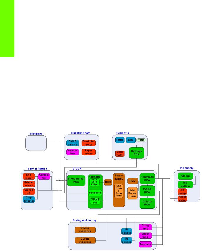
The electrical system controls all the printing systems and the heating systems inside the printer. Most parts of the control electronics are placed inside the ’E-box’.
Components
The electronics can be divided into different functional subsystems and will be described in such a way. There are 6 functional subsystems within the electronics, Front panel, Substrate path, Scan axis, Service Station, Ink Supply and Dryer and Curing.
•E-box: Main electrical control system of the printer, used for processing and controlling the various printer elements.
•Front Panel: The Front Panel receives its control and power from the Interconnect PCA.
•Substrate Path: Controls the substrate movement.
•Scan Axis: Pen firing control and sensors for color and paper detection.
•Service station: Maintenance of the Printheads.
•Ink supply: Control of ink.
•Dryer and Curing: Infrared (IR) Sensors and Heaters for Latex ink.
Circuit diagram
2 |
Printer systems |
E-box
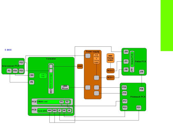
Description
The E-Box contains all the electronics except for the Ink Supply and the control of the firing of the Printheads which take place outside the Ebox.
Components
|
|
|
2 Residual |
|
|
Printmech |
|||
|
PATA to |
|
Chindra |
(behind |
|||||
Formatter Main PCA |
HDD |
Circuit Current |
|||||||
(vertical |
Heaters |
||||||||
|
SATA bridge |
|
Breakers (RCCD) |
control |
|||||
|
|
|
|
|
orientation) |
||||
|
|
|
|
|
|
|
assembly) |
||
|
|
|
|
|
|
|
|
|
|
|
|
|
|
|
|
|
|
|
|
|
|
|
|
|
|
|
|
|
|
|
|
|
|
|
|
|
|
|
|
Printer systems
|
OMAS |
Sausalito |
Power supply (contains |
|
Controller |
|
|
Interconnect |
|
the combined electrical |
|
|
|
||
PCA |
|
|
input for the printer and |
|
|
|
Curing assembly |
Electrical input |
Heating and |
for the Dryer |
Curing control |
Assembly |
module |
|
(Petisa) |
Functionality
Formatter Main PCA
The formatter is the motherboard of the printer, referred to as the Main Board and is the same type as for a standard PC.
PATA-SATA bridge
The Main Board does not support SATA hard disk drives and a converter board is used to convert from serial data to parallel data.
Hard Disk Drive (HDD)
The HDD contains the firmware of the printer.
•The operating system is based on Montavista’s embedded Linux system.
•All calibration values, product number, serial number etc, are stored on the Hard Disc Drive. In order to make sure that this information is not lost in the case of a failure of the HDD, a backup is made in the ISS top board
NOTE: In order to prevent any loss of calibration values do not replace the following at the same time
•Do not replace the Hard Disc and the ISS Top Board.
•Do not replace the Hard Disc and the Main Interconnect Board
Sausalito PCA
This board is the main controller of the printer, it is responsible for all the processes performed in real-time and are the ultimate controllers of all electromechanical systems. Sausalito controls all substrate path
Printer systems |
3 |

Printer systems
components (Drive Roller, Spindle Motors, OMAS, etc.) and all non-substrate path components (Carriage, Scan Axis Motor, Dryer and Curing Heaters, Print Head Cleaning Assembly, Service Station, etc).
Printmech
The ‘printmech’ PCA is mainly used to control motors and fans but it also controls the following:
• |
Scan motor |
• |
Top fans |
• |
Paper motor |
• |
Dryer fans |
• |
Rewinder motor |
• |
Curing fans |
• |
Ink valves |
• |
Web-wipe |
• |
Ink pressurizing |
• |
IR sensor |
|
pumps |
• |
IR Fan |
The Interconnect PCA
The Interconnect PCA controls several motors and is also used as a connections board for some of the functionality that resides in Printmech board.
•Take-up reel
•Vacuum fans (passes through, the actual control is inside Printmech)
•Front panel
•TOMAS (temperature sensor for the OMAS sensor)
•Valves
•Paper Jam Sensor
Heater Control Board (Petisa)
The Heaters Control Board (Petisa) is a high voltage board with TRIACS, relays, current sensors and safety components for the external heaters. It has its own Enclosure for safety protection.
Chinda
Chinda board controls the TRIACS and interfacing with a digital interface. It is installed vertically into the Petisa board.
In order to avoid incorrect installation this PCA has a tab, which must be correctly aligned with the Petisa board before being fully installed.
 Tab and Slot
Connector
Residual Circuit Current Breaker (RCCB)
To protect the printer and the users, there are two Residual Circuit Current Breakers (RCCB) which are connected between the two power inputs and the Heater Control board. They detect a current leak greater than 30mA. The customer can reset the RCCB if a circuit blows, but a frequent reoccurrence would indicate an electrical failure in one or more of the heaters.
Printer/Curing Assembly Power supply
The power supply converts the AC input of the following skus:
•42inch Printer: 200-240VAC
•60inch Printer: 220-240VAC
4 |
Printer systems |
They are converted to voltages that can be used internally in the ’E-box’ for driving the electronics, motors etc. This input is also used by the curing heater.
Power Input for the Dryer Assembly
This input is solely used by the resistors in the Dryer Assembly.
Circuit diagram
The following diagram shows the connections between the components and the ebox.
Printer systems
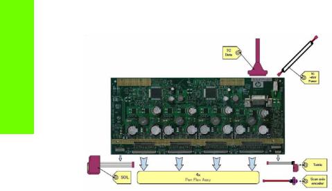
Carriage Electronics
The Carriage contains the electronics for controlling and firing the Printheads. It also contains electronics for controlling the external sensors (SOL and Tetris) as well as the Scan Axis Encoder.
The electronics of the Carriage receives power and data from the Trailing cables, which conveys both Power (+45V) and Data (LVDS) cables. The Power cable connects the Carriage with the Printmech board and Data cable connects Carriage with the Main (Engine) board)
Components
Carriage PCA
The Carriage PCA contains the electronics to control how and when the ink is dropped in every print head and receives the information from the sensors.
Printer systems |
5 |
Printer systems
SOL Spectrophotometer
The SOL is a color sensor located on the left side of the Carriage. A metal sheet is protects the SOL from the high temperatures produced by the Dryer Assembly. The main function of SOL is to measure color samples that have been printed on the loaded media and then are placed on the print platen zone.
Before taking any color measurement, the SOL must be initialized. The SOL initialization process takes approximately 7min. This process consists of three steps:
•Sensor switch on
•Sensor warm up
•Sensor calibration.
When the initialization process has finished, the shutter opens automatically and the Carriage is moved along the Scan Axis to place the SOL on top of each sample to take a color measurement. After the measurements, the shutter is closed again and the sensor is switched off.
Tetris
Tetris is used to align the printheads as well as to locate and measure a media size and edges. The alignment procedure consists of a series of patterns first being printed, then scanned using the Tetris, and finally an internal process is used to correct the timing of when and where the nozzles of the Printheads fire, and detect any possible nozzle-out issues.
Scan axis encoder
The line encoder is located on the Carriage and this measures and counts the movements of the Scan Axis. An optical, infrared wavelength encoder is used, this is the same type of encoder used in most of the HP large format printers. The Encoder signal is converted to LVDS logic levels and directly routed through the Data TC.
Pen Flex
To connect the Carriage to the Printheads, a delicate flexible circuit with small golden dimples is used. Printheads are inserted into unique slots and a spring loaded mechanism pushes the electrical contacts of the Printheads into the Printhead flex, which subsequently connects the Printhead to the Carriage electronics. Printheads Flexes are the most delicate and sensitive part of the Carriage. If the Printheads are inserted with too much force or they are misaligned, the insertion can easily damage them.
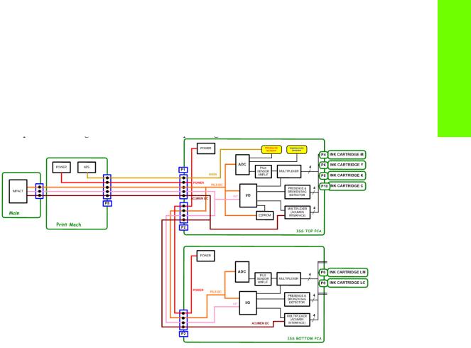
Ink Supply Station (ISS) Electronics
Description
The ISS electronics is powered from a +12V line coming from the PrintMech, and a linear regulator on the ISS PCAs generates the +5V used to power all the devices on the board.
6 |
Printer systems |
The ISS PCAs are two electronic PCAs located on the rear of the Ink Supply Station. The ISS PCAs provide the following:
•Pressure Ink Level Sense (PILS) measurement.
•Ink supply presence detection.
•Ink Cartridge broken bag detection.
•Ink supply smart chip interface.
•Air pressure measurement and air pump shutdown.
•Humidity and temperature measurements.
•System back-up EEPROM.
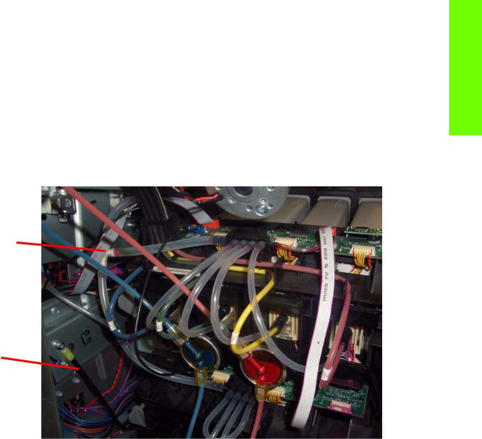
Components
Below is a picture showing the connections and components located at the rear of the ISS.
Printer systems
C

 A
A  E
E
F 
 D
D

 B
B
Marking |
Description |
|
|
A |
ISS Top PCA |
|
|
B |
ISS Lower PCA |
|
|
C |
ISS to Printmech cable |
|
|
D |
ISS Top to lower cable |
|
|
E |
ISS Supplies cable |
|
|
F |
ISS Ground cable |
|
|
Top and Lower ISS PCAs
Both top and lower ISS PCAs share the same PCB, the only difference between them is that the lower PCA is a simplification of the top PCA, the top PCA contains these additional parts:
•EEPROM
•Connection from the Printmech
•Air pressure sensor
Printer systems |
7 |

Printer systems
•Temperature and Humidity sensor
Both PCAs are connected through an 8-pin connector. The 2nd ISS connector is connected to the PrintMech in a daisy-chained connection the 1st ISS board by means of this 8-pin connector.
All the board functionality is controlled by means of two I2C buses: PILS_I2C and ACU_I2C. The bus controllers are inside the ASIC, placed on the main PCA.
The PILS_I2C bus is operated at 400 KHz and the devices connected to it are an I/O Expander, an ADC and the Back-up EEPROM. The functionality of each of these devices is explained below.
•I/O Expander: Used for Presence and Broken Bag detection. It generates an interruption each time a presence event or a broken bag event occurs. This interrupt line is taken to an Impact GPIO. The I/ O expander also controls the multiplexers for the PILS measurement circuitry and the Acumen interface. The device contains 16 I/O ports.
•ADC: This measures the PILS signal, and the signals coming from all the sensors on the PCA, i.e. temperature, humidity and air pressure sensors. It is a 12-bit, 8-channel A/D converter.
•EEPROM: 32KByte memory for storage of tubes and system back-up information (NVM).
The other I2C bus, the ACU_I2C, is operated at 100 KHz and it is used to communicate with the Ink Supply Acumen. This bus is multiplexed on the ISS board through an analog multiplexer.
The ISS is connected to the PrintMech through a 10-pin connector. The pins-out of this connector are listed in the following table, together with a description of all the signals:
Pin # |
Pin Name |
Description |
|
|
|
1 |
GND |
Ground. |
|
|
|
2 |
+12 V |
12 Volts to power the ISS board. |
|
|
|
3 |
ACU_SDA |
Data line of ink supply I2C acumen interface. |
|
|
|
4 |
ACU_SCL |
Clock line of ink supply I2C acumen interface. |
|
|
|
5 |
PWM_OFF |
Signal to shut down air pump PWM in PrintMech in case of overpres- |
|
|
sure. |
|
|
|
6 |
ISS_INT |
Interrupt to alert Impact of a presence detection or broken bag event. |
|
|
|
7 |
ADDR |
Signal sets the I2C slave address of ISS devices and allows for |
|
|
expandability in case a 2nd ISS board is needed for a future product. |
|
|
|
8 |
PILS_SDA |
Data line of the PILS I2C interface. |
|
|
|
9 |
PILS_SCL |
Clock line of the PILS I2C interface. |
|
|
|
10 |
GND |
Ground. |
|
|
|
Besides the PrintMech connector, there is an 8-pin connector to allow for expandability with the 2nd ISS board (lower PCA). The 2nd ISS connector is connected to the PrintMech in a daisy-chained way through the 1st ISS board (top PCA) by means of this 8-pin connector. The pins-out of this connector are listed in the following table, together with a description of all the signals:
Pin # |
Pin Name |
Description |
|
|
|
1 |
GND |
Ground. |
|
|
|
2 |
+12 V |
12 Volts to power the ISS board. |
|
|
|
3 |
ACU_SDA |
Data line of ink supply I2C acumen interface. |
|
|
|
4 |
ACU_SCL |
Clock line of ink supply I2C acumen interface. |
|
|
|
8 |
Printer systems |
5 |
ISS_INT |
Interrupt to alert Impact of a presence detection or broken bag event. |
|
|
|
6 |
PILS_SDA |
Data line of the PILS I2C interface. |
|
|
|
7 |
PILS_SCL |
Clock line of the PILS I2C interface. |
|
|
|
8 |
GND |
Ground. |
|
|
|
Circuit diagrams
A simplified block diagram:
Related tests, utilities, and calibrations
•Electrical system Menu Page 123.
Service parts
•Electronics Module Page 268.
•Carriage PCA Page 278.
•Left Hand Assemblies Page 276
Removal and installation
•Electronics Module Page 483.
•ISS Upper and Lower PCAs Page 391.
•ISS to Cartridge Cables Page 385.
•Carriage PCA Page 402.
•Carriage Flex Cables Page 405.
•Interconnect PCA Page 435.
•OMAS Controller Card Page 437.
•Sausalito PCI PCA Page 444.
•Memory Modules Page 448.
•Main PCA Page 450
•Hard Disk Drive Page 452
•Pata to Sata PCA Page 454
•Power Supply Page 456
•Formatter Battery Page 464
Printer systems
Printer systems |
9 |

Printer systems
•Heater Control Assembly Page 465
•Circuit Breakers Page 476
•Dryer AC Input Page 478
•Printmech Page 482
10 |
Printer systems |
Substrate path
Description
The substrate path moves the substrate from the input spindle to the take-up reel, through the print path, while the Carriage prints on the substrate. The objectives of the substrate path while advancing the substrate are:
•Maintain an accurate advance
•Maintain a constant advance
•Keep the substrate flat
•Advance the substrate straight along the substrate axis
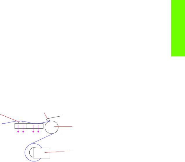
Substrate path workflow overview
The following steps describes the substrate path workflow.
1.The substrate is loaded onto the Input Spindle (1) which is driven by the rewinder mechanism to provide back tension to the media. The media is fed through the entry platen, around the Drive Roller (2), under the Pinchwheels (3), over the printzone and Overdrive (4) and finally the media is either left free or collected in the take-up reel.
4. Overdrive |
3. Pinchwheels |
2. Drive Roller
Vacuum
1. Rewinder: Input Spindle and Media roll
2.The rewinder has a motor that primarily acts as a brake to maintain tension on the media.
3.The drive roller also has a motor, and is the primary component that advances the substrate. The substrate is pressed to the drive roller by the pinchwheels, ensuring a smooth substrate advance. The motor receives feedback from an encoder located at the left side of the roller, inside a protected enclosure on the left of the left sideplate.
4.The surface of the substrate path where the substrate is printed is called the print platen. The print platen is designed to give minimal resistance to the substrate advance, and includes suction holes which apply vacuum to the substrate.
5.The vacuum, is calibrated according to the substrate type and print options used, it draws the substrate to the print platen, making sure that the substrate is flat. The media is also under the dryer when it is in the print zone.
6.The area of the platen in front of the print zone holds the overdrive wheels. This area also has vacuum to ensure traction over the wheels, which are connected to the drive roller through a set of gears. The overdrive wheels help to remove the substrate from the print zone during the substrate advance.
7.After the platen, the substrate goes through the curing zone and finally leaves the printer, either to be collected on the take-up reel or to be cut.
8.The printer detects and controls the substrate’s advancement. The OMAS sensor, located on a special cutout section of the print platen, is a sensor which is able to detect very small errors in the advancement of the media. These advancement errors are communicated to the motors on the driver roller and small corrections adjustments are applied to the movement of the substrate.
Printer systems
Printer systems |
11 |

Printer systems
Under the same area, but not visible from outside the printer, there is the TOMAS sensor which measures the temperature in the area and helps OMAS to provide the drive motors with a higher degree of accuracy.
NOTE: The OMAS sensor cannot see the fibers on some substrates, such as transparent media or very dark or very reflective substrates. In these cases, the OMAS sensor can be disabled. To disable the OMAS sensor See page 189.
Startup, substrate load, substrate selection
During startup, the printer checks that the substrate path components are functioning correctly. When shutting down, if a substrate is loaded, the printer remembers the substrate definition. This may be modified through the front panel with the option ’Change loaded substrate’ from the substrate menu list.
During substrate loading the printer may ask the user two interactions:
1.To rewind manually the media: The printer automatically checks the direction of the loaded media (printed face outwards or printed face inwards). If the ’curve’ of media is too large the printer cannot detect it and the printer asks the user to rewind manually. Once the media is rewound the printer can detect automatically
2.To align the substrate in order to avoid skew: the printer measures skew. If the skew is too large the printer will ask the user to lift the pinchwheels (big blue lever on right hand side) and align the substrate. The substrate must be aligned against itself (media edge must be aligned with input roll edge).
Components
Spindle
65mm (2.6 inches)
The spindle can load 3” core rolls. It holds the core of the roll when its rubber bands are nipped between the core of the roll and the aluminum extrusion.
The hub on the left side has two possible fixed positions: the end position allows loading maximum width rolls, but there is a second position at 2.6 inches (65mm) from the end that can be selected.
The right hub can be set along any length of the spindle so any length of roll can be loaded.
The right end of the spindle contains a gear which is used to transmit the movement from the rewinder to the roll.
12 |
Printer systems |

Loading table
Printer systems
Loading table
You can use the loading table as a working surface to load the substrate roll onto the spindle In order to position the spindle, use the two slots on the right hand side. Right hub should go inside one of them. Then, by rotating the table towards the machine, the roll will go to its final position with a small amount of effort. The user is asked to check that both spindle ends have entered into the final positions.
Spindle latch
The spindle latch prevents the media roll |
Spindle latch |
from slipping from its position when |
|
printing. It is not necessary to close it when |
|
inserting the spindle, it closes |
|
automatically. But the user must lift the small |
|
blue lever in order to release the spindle |
|
and extract the roll of media |
|
Rewinder |
|
|
The rewinder motor keeps a constant |
Rewinder motor |
|
tension on the input media to prevent skew |
||
|
||
problems. There is a motor and a |
|
|
transmission that gives torque to the |
|
|
spindle in order to provide the necessary |
|
|
back tension. |
|
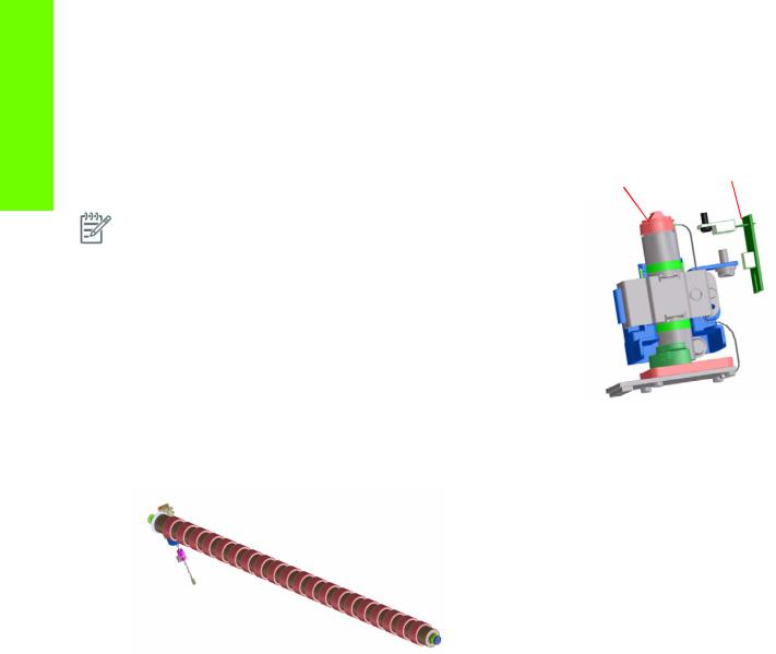
Media sensor
The entry platen has a lever that activates the media sensor whenever media is present. When the substrate is inserted into
the entry area, the sensor is activated and the drive roller starts turning to help the loading process. The media load process has been triggered and the printer will provide instructions through the front panel.
OMAS sensor (substrate advance sensor) |
|
|
OMAS is located under the third platen slab from |
OMAS |
|
the right, only the top window can be seen: |
||
|
||
OMAS is composed of two parts: the sensor and |
|
|
its optics located under the platen and a PCI |
|
|
control board on the main electronics box. Both |
|
|
are connected through a ribbon cable that runs |
|
|
through the vacuum beam, by the right sideplate |
|
|
and into the electronics box. |
|
|
The optical sensor detect the surface of the back |
|
|
of the substrate as it moves across the platen. The |
|
|
sensor is able to evaluate the exact movement of |
|
OMAS location
Printer systems |
13 |
Printer systems
the substrate, and communicate any small adjustments required by the system to move the substrate smoothly.
The window of the OMAS sensor must be cleaned of dust and ink to functioning correctly. The cleaning procedure for this is described in the customer document ‘Maintenance and Troubleshooting guide’, in the section called ‘Clean the substrate advance sensor window’.
During the substrate load, the printer detects that the substrate has |
TOMAS sensor |
|
reached the print platen when the OMAS captures its image. |
||
OMAS sensor location |
||
|
||
NOTE: The OMAS sensor cannot detect the surface of some |
|
|
substrates, such as plastic or very dark substrates. In these cases, the |
|
|
OMAS sensor must be disabled, and instead the printer uses |
|
|
feedback from the Driver Roller encoder to calculate the substrate |
|
|
advance. To disable the OMAS sensor, locate the OMAS Sensor |
|
|
selector from the print options menu of the RIP and set it to OFF. This |
|
|
can also be done from the Service menu Page 189. |
|
|
|
|
TOMAS
To compensate for temperature changes and mechanical expansion,
OMAS receives a temperature reading from TOMAS sensor.
Drive roller and motor
The drive roller and motor advance the substrate through the substrate path. The motor requires 24 V, and is controlled by the Printmech PCA.
Drive Roller Encoder Disc and Encoder PCA
The Drive Roller Encoder Disc and Encoder PCA provide the feedback system for the Drive Roller.
•The Encoder disc is a round disc mounted to the left end of the Drive Roller.
•The Encoder PCA is mounted with a sensor that reads the encoder movements of the disc (the disc turns with the drive roller).
Pinchwheels
The pinchwheels press the substrate against the Drive Roller to make sure that the Drive Roller can advance the substrate correctly.
•The pinchwheels are activated with the blue lever at the right side of the media roll and usually do not have to be lifted unless to correct skew during substrate load or to clear jams.
•The pinchwheel system has a sensor that detects if the system is up or down.
Vacuum Pump, Vacuum Tube Assembly, Vacuum Beam
The print zone is the area of the media path where the transmission of ink to the substrate occurs. The main function of the system can be defined as providing the surface where the media is printed, keeping it controlled during the process, playing a main roll on the final IQ of the plots and on the operational reliability of the printer. The subsystem is composed of the print platen assembly (including the overdrive wheels), which is the physical interface with the substrate, and the vacuum system which is the mechanical system where the vacuum pressure used to control the media is generated and conduced.
14 |
Printer systems |
The HP Designjet L25500 printers requires a hot print zone (with additional airflow) to allow the evaporation of the majority of the water in the latex inks. This feature, plus the new media supported, changes a little the main contributors of the cockle control and media expansion from the former products and also adds new issues such as the thermal marks. The platen gives a convenient shape to the heated media, avoiding differential temperatures because of platen conductivity.
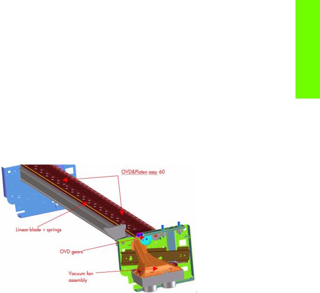
The main components for 60’’ SKU are:
•OVD & Platen assy 60 including:
•7 DJ25500 printer platen + 1 OMAS platen + 1 interplaten 60 + 1 platen right end + 1 platen left end
•Linear blade 60 + springs (same as DJZ6100)
•OVD shafts and wheels (same as DJZ6100)
•Foams, foam fillings and foam wall
•ESD brushes
•OVD gears (same as DJZ6100)
•Vacuum Fan Assembly shown below (same as DJZ6100)
•OVD & Platen assy 42 including:
•Five DJL25500 platen + 1 OMAS platen + 1 platen right end + 1 platen left end
•Linear blade 42 + springs (same as DJZ6100)
•OVD shafts and wheels (same as DJZ6100)
•Foams, foam fillings and foam wall
•ESD brushes
•OVD gears (same as DJZ6100)
•Vacuum Fan Assembly includes a new foam structure which improves the control of the vacuum.
Related tests, utilities, and calibrations
•Rewinder test Page 133.
•Drive Roller test Page 135
•Substrate Path sensor test Page 138
•Vacuum Test Page 142.
•OMAS Test Page 142.
•Rewinder Motor polarity test Page 143
•Media path menu Page 188
•Substrate advance adjustment Page 197
Printer systems
Printer systems |
15 |

Printer systems
Service parts
•Drive Roller Page 288.
•Media Path Assemblies Page 290.
•Center guide Pinchwheels Assemblies Page 292.
•Media Entry Assemblies Page 294.
•Take-up reel Assemblies Page 296.
Removal and installation
•Rewinder Page 361.
•Vacuum Fan Page 370.
•OMAS Page 424.
•TOMAS Page 431.
•Output Platen Page 533.
•Center Platen Page 538.
•Input Roller Page 550.
•Output Roller Page 552.
•Media Sensor Page 555.
•Pinchwheel Assembly Page 565.
•Center Guide Page 571.
•Driver Roller Page 573.
•Rollfeed Modules Page 579.
•Take-up reel Page 582.
16 |
Printer systems |
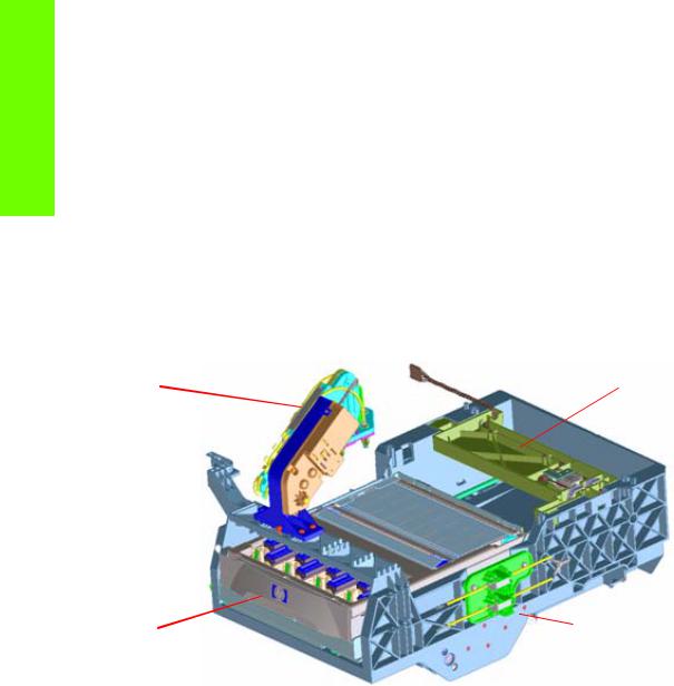
Ink Delivery System (IDS)
Ink Delivery System
The ink deliver system (IDS) is located in the left enclosure of the printer (inside the left covers) and delivers a continuous supply of ink to the printheads. It can detect an ink leakage anywhere in the system, including inside an Ink Cartridge. It also tracks and determines when an Ink cartridge needs replacing.
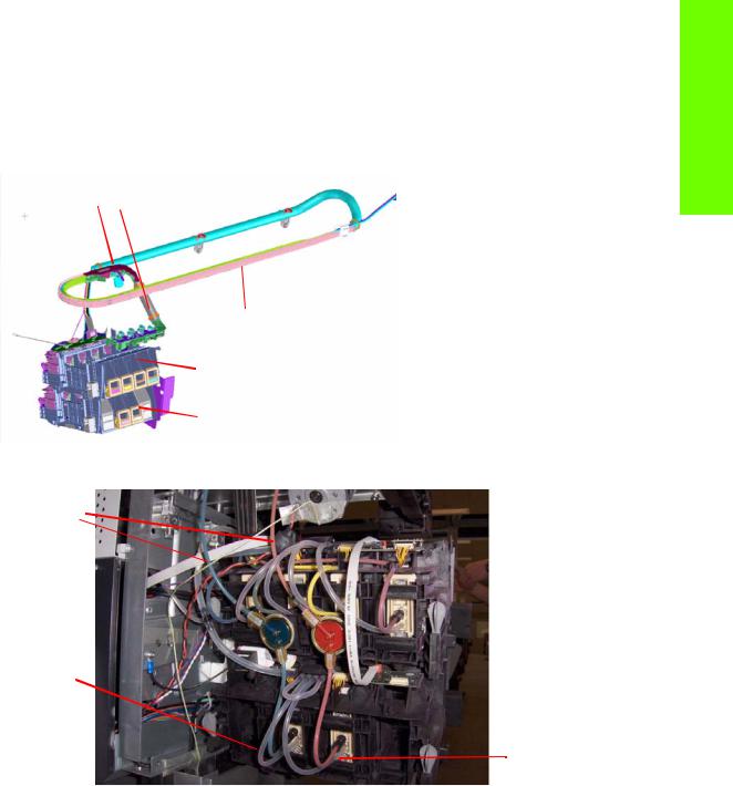
Insulation sleeve
Ink Tubes Carrier
Top ISS: M, Y, K, C
Lower ISS: Lm, Lc
Rear of the Ink Supply Station
Ink tubes
Air tubes
On top of the ISS there is a thin plastic sleeve to avoid the paper falling into the Ink Supply Station when a paper crash occurs and also to avoid the direct heat radiation from the dryer system
non-return valves  for the lower ISS
Spring loaded
Ink Tubes
There are 6 ink tubes that deliver the inks to the printheads in the carriage and two additional tubes which are used as a support structure. They are bundled together in a carrier and held on a shelf on the inside of the top cover with clips.
Insulation Sleeve
The ink tubes are protected from the high temperatures of the Dryer Assembly by a heat resistant insulation sleeve, which protects the main body of the tubes, that are static.
Upper and Lower Ink Supply Station (ISS)
The Ink Supply Station (ISS) is divided into the upper and lower sections. They have six slots for holding the ink cartridges. Each slot has a unique shape (or lock out) which matches with an equal shape at the end of the applicable ink cartridge. this arrangement avoids the incorrect insertion of an ink cartridge, which would cause major damage to the ink system.
Printer systems
Printer systems |
17 |
Printer systems
There are two places for additional slots but these are covered over.
The upper and lower ISS both contain PCAs, although the top PCA contains more functionality, such as the pressure sensor, see Page 6.
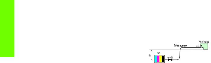
Non-return valves
The two non-return valves are only for the inks on the lower IDS. This is to ensure that when the pump stops and the cartridges are nearly empty, that the ink does not flow back to the cartridge.
If a cartridge is nearly empty, with no pressure from the pump, the cartridge bag might increase, and air might enter the printhead.
With a valve, the ink can go only from the cartridge to the printhead, and not the reverse!
Air Pressure System (APS)
The APS contains two air pumps which are used to force the ink through the tubes to the carriage assembly. In the event of a broken bag in one of the Ink Cartridges, these tubes must be checked in case any of the leaked ink has been forced into the air tubes.
Related tests, utilities, and calibrations
•Ink Delivery System tests: Page 146.
Service parts
•Left hand assembly: Page 276
Removal and installation
•Ink supply tubes and trailing cable: Page 380
•ISS to Cartridge Cables: Page 385
•Ink Supply Station: Page 388
•Ink Supply Station PCAs: Page 391
•APS Assembly: Page 395.
•APS Assembly: Page 395.
18 |
Printer systems |

Scan Axis and Carriage
Scan Axis
The Scan Axis System is the part of the Scan Axis subsystem designed to move the carriage backwards and forwards for printing and servicing. This subsystem moves the carriage with a motor, belt, and pulley system. Furthermore the scan axis has features to open and close the Spectrophotometer shutter (SOL) and to enable/disable the cutter.
Scan Axis Components
Scan Beam:
It is an extruded aluminum part. Its main function is to guide the carriage along the scan axis via two rods, and it sets its limits of movement. Apart from this it positions and holds the Service Station, the Scan Axis motor, the two brackets and the pinch wheels assembly. It also works as an air container to be blown to the print zone coming from the rear and leaving through several pipes located over the media and holds the rear fans.
PPS system
The PPS consists of some screws and pockets, it locates the scan beam in reference to the side plates in order to have a correct distance between the printheads and the media. This distance is supposed to be constant during the life of the machine and it is set to be as small as possible without taking the risk the having the printheads touching the media.
Left Bracket
Left Bracket is an injected plastic part, and its main function is to set an end for the carriage movement. It also closes the scan beam to avoid the air blown to the print zone leaking. It has several features to enable/disable the cutter and the SOL shutter. The left bracket also houses the Media Jam Sensor, which works with the reflector panel on the carriage assembly to detect paper crashes. It also has some parts to ensure that the encoder strip is held with tension.
Encoder Strip
The Encoder Strip contains positional data that the encoder sensor (located in the carriage) can read and detect the position of the carriage. Since it is made of thin metal it is sharp and extreme caution is needed when handling it. Unlike previous versions, do not clean the encoder strip as this will damage it.
Right Bracket
This part is the same in the left bracket, this metallic part closes the right hole of the scan beam extrusion. It also holds the pulley assembly and the encoder strip.
Motor, pulley assembly and belt.
Their function is to transmit the position/speed to the carriage assembly.
Flat right bump
This plastic part defines the right end of the carriage movement. It is positioned and held by the scan beam.
Carriage
The carriage is the subsystem of the printer that performs the printing on the substrate. It is moved across the print path by the scan axis impelling system and with it the 6 printheads and several sensors, the Spectrophotometer (SOL), the line sensor (Tetris), the scan axis sensor. The carriage houses an on-board electronics system to send information to the 6 printheads though each of the interconnects, and it receives information from the sensors. Some parts aid the ink to arrive at the printheads. It also holds in position the cutter, used to cut some types of media.
Printer systems
Printer systems |
19 |
Printer systems
Carriage Components
SOL Spectrophotometer
SOL is a color sensor and it is placed in the left side of the carriage, covered by a metal sheet that protects it from the heater’s high temperatures. The main function of SOL is to measure color samples that have been printed on the loaded media and are placed on the print platen zone.
Before taking any color measurement, SOL must be initialized. The SOL initialization process lasts for about 7min. This process consists on 3 steps: sensor switch on, sensor warm up and sensor calibration. When the initialization has been completed, the shutter is opened automatically and the carriage is moved along the scan axis to place SOL on top of each sample to take a color measurement. After the measurements, the shutter is closed again and the sensor is switched off.
SOL is used to make the linearization from the RIP.
SOL
SOL actuator used to open the shutter
Carriage base
The main function of this plastic part is to located the printheads. Its position is enforced by the two rods and the belt. It serves as a base where other parts are attached and it has some features to located other components (capping station and all the next parts).
Latch assembly
This assembly holds down the printheads and helps to ensure that they do not move during operation. Once the handle is opened it can rotate to allow the user to remove the printheads. It has some features (holes) to allow the primer to pass though it and make contact with the printheads. Some parts help to transmit force to the printheads to hold them in position and to transmit information of when the ink should be dropped.
Sensors
The SOL, the Tetris and the encoder sensor sends information to the PCA board and is passed to the printmech though the trailing cable. The SOL performs a color calibration, the line sensor calibrates the printhead alignment and detects other features (e.g. the media) and the encoder sensor detects the movement of the carriage in relation to the Encoder strip.
Carriage PCA,
This part contains the electronics to control how and when the ink is dropped in every printhead and receives the information from the sensors.
PCA Cover
This part covers the PCA to avoid aerosol contamination and acts as an electronic enclosure.
X-bias springs
The X-bias springs are sheet metal parts that hold the printhead in position in the X axis.
Covering sheet and metal parts
These parts reflect part of the radiation that is received from the heater to avoid excess overheating and problems with the sensors and the printheads. Bushings, are bronze parts that are attached to the carriage base and slide over the rod
20 |
Printer systems |

Felts, these parts help to lubricate the rod and they also avoid dirt going in between the carriage. They block four degrees of freedom (Z and Y translation and rotation over the primary rod)
SOL protectors, these parts help to avoid the SOL shutter breaking after a paper jam
Plastic rear bushing : this blocks one degree of freedom (the X rotation over the primary rod). The dam protector, are Mylar and stainless steel, and they stop the aerosol.
The plastic non-functioning pen, is a plastic part which helps keep the carriage’s integrity when the latch is applied over them. Also from a usability point of view, they avoid possible mistakes when inserting the pens and have a cosmetic function too.
The airflow deflector is a part that partially stops the air entering into the print zone, it is used to avoid vapor concentration over the media that also causes “dpe” (drop placement error).
Media Jam reflector
This part is secured to the left ide of the carriage assembly and works with the Media Jam sensor which is located on the Left end bracket. This is used to detect media jams.
Printer systems
Related tests, utilities, and calibrations
•Scan Axis Menu service tests: Page 157.
•Carriage service tests Page 161.
•Open/close SOL Page 223.
•Scan Axis Calibrations Page 213.
•Carriage Calibrations Page 217
Service parts
•Right hand Assemblies Page 274
•Left hand Assemblies Page 276
•Carriage Assembly Page 278.
•Scan Axis Assemblies Page 282.
Removal and installation
•Cutter Assembly Page 386.
•Encoder Strip and Encoder sensor Page 399.
•Carriage Assembly Page 408.
•Belt Assembly Page 418.
•Scan Axis Motor Page 419.
•Line Sensor Page 486.
•Color Sensor Assembly (SOL) Page 488.
•Color Sensor Actuator Page 492.
Printer systems |
21 |
Printer systems
Service Station and Waste management
The main function of the Service Station is to maintain the Printheads of the Carriage assembly and to manage the Waste Ink. The Service Station and Waste Management can be split into three subsystems:
•PHC servicing: Comprising Cap, wiping and priming functions
•Waste: Holds spit, ink collection and containment.
•Aerosol: Collection and filtration of aerosol generated in Spit
Components
SVS Mech
The SVS mechanics provides the movement for the Printhead cleaning Maintenance Cartridge, which integrates the capping and wiping functions and the Web Wipe assembly, which provides the means in which to advance the Web Wipe accurately.
Primer |
Web Advance |
|
Mechanism |
Printhead Cleaner |
SVS Mech |
Maintenance Cartridge |
|
Primer
The Primer executes the blow primer functionality to the Printheads. Air pressure to perform the prime operation is drawn from the Ink Supplies, and prime pulse is controlled by solenoid valves.
Printhead Cleaner Maintenance Cartridge
The Printhead Cleaner Maintenance Cartridge is a customer consumable that holds the main components for wiping and capping. It also contains some ink priming functionality.
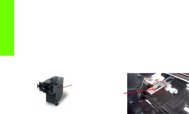
Drop detector
The drop detector is a sensor that analyzes the nozzle health of all the pens. The drop detector has a window where it is placed with the ink funnel. The ink funnel divides the window in two different parts, the flying spittoon and the drop detector spittoon where nozzles are fired to check their status. The nozzles out that are detected are compensated for by using other nozzles to keep a good print quality.
The drop detector has an infrared LED and a photodiode aligned in a beam light. This beam light can be blocked by the ink funnel if it is not placed correctly.
22 |
Printer systems |
Loading...