


Designjet 650C

PrinterFAQ.COM
HP DesignJet650C
User Guide
HP C2858A/C2859A
DRAFTING PLOTTERS
SERVICE MANUAL
SERIAL NUMBERS
This manual applies directly to HP C2858A and C2859A
plotters with serial numbers prefixed USA.
For additional information about serial numbers, see
SERIAL NUMBER INFORMATION in Chapter 1.
HEWLETT-PACKARD COMPANY 1993
16399 W. BERNARDO DRIVE
SAN DIEGO, CALIFORNIA 92127-1899
C2858-90000 Printed: March 1993

Using this Manual
Using this Manual iii
This service manual contains information necessary to test, adjust, and service the
Hewlett-Packard Models C2858A and C2859A DesignJet 650C plotters. It is designed to
help you easily find the cause of a C2858A/C2859A hardware problem and to perform the
necessary repairs and adjustments to get the plotters into proper operating condition.
Service strategy for this manual is to support the products to the field replaceable unit.
For ease of reference, this manual is divided into ten chapters as follows:
Chapter1 Product Information
Chapter2 Site Planning and Requirements
Chapter3 Installation and Configuration
Chapter4 Preventive Maintenance
Chapter5 Functional Overview
Chapter6 Removal and Replacement
Chapter7 Adjustments/Calibrations
Chapter8 Troubleshooting
Chapter9 Product History
Chapter10 Parts and Diagrams
Chapter 1. Product Information
This chapter contains general information regarding the C2858A and
C2859A DesignJet 650C plotters. A description of the plotters features,
options and accessories, performance characteristics, and serial number
information, is included in this chapter.
Chapter 2. Site Planning and Requirements
Included in this chapter is pre-installation information regarding the
physical, environmental and electrical requirements for proper installation
and operation of the plotters.
Chapter 3. Installation and Configuration
In this chapter you will find installation, configuration and plotter
verification procedures. Included is information on ink cartridge and media
loading, accessing the front-panel menu structures for plotter configuration
and instructions on how to perform built-in demonstration plots to verify
proper plotter operation.

Using this Manualiv
Chapter 4. Preventive Maintenance
Chapter 4 contains information you will need to keep the plotters in their
best operating condition. Included are procedures that can be performed by
the user.
Chapter 5. Functional Overview
This chapter contains a simplified description of the plotter circuits and
mechanical functions.
Chapter 6. Removal and Replacement
Procedures for the removal and replacement of field replaceable units are
provided in this chapter along with electrostatic discharge information and
recommended tools to perform repairs.
Chapter 7. Adjustments
Here you will find descriptions of any adjustments and calibrations that may
be required to return the plotter to proper operating condition.
Chapter 8. Troubleshooting
Included in Chapter 8 are service tests, error codes and messages, and
diagnostic information to assist you in troubleshooting and solving plotter
symptoms and failures.
Chapter 9. Product History
Chapter 9 provides historical tracking of changes made to the plotters. The
differences between earlier versions of the plotters and the version
described in the main body of this manual are identified.
Chapter 10. Parts and Diagrams
In this chapter you will find drawings for purposes of identifying the various
field replaceable assemblies. Also in this chapter are associated parts lists
for ordering replacement parts shown on the drawings.
Glossary
The glossary contains a listing of terms used throughout the manual.
Index
Use the index to find references and locate subject matter in this manual.

Contents
vContents
Chapter Page
1 Product Information
Introduction 1-1. . . . . . . . . . . . . . . . . . . . . . . . . . . . . . . . . . . . . . . . . . . . . . . . . . . . . . .
Description 1-2. . . . . . . . . . . . . . . . . . . . . . . . . . . . . . . . . . . . . . . . . . . . . . . . . . . . . . . .
Options 1-4. . . . . . . . . . . . . . . . . . . . . . . . . . . . . . . . . . . . . . . . . . . . . . . . . . . . . . . . . . .
Plug-in Memory 1-4. . . . . . . . . . . . . . . . . . . . . . . . . . . . . . . . . . . . . . . . . . . . . . . .
ROM Enhancement Modules 1-4. . . . . . . . . . . . . . . . . . . . . . . . . . . . . . . . . . . . . .
Modular Input/Output (MIO) PCAs 1-4. . . . . . . . . . . . . . . . . . . . . . . . . . . . . . . . .
Accessories 1-5. . . . . . . . . . . . . . . . . . . . . . . . . . . . . . . . . . . . . . . . . . . . . . . . . . . . . . .
Performance Characteristics 1-6. . . . . . . . . . . . . . . . . . . . . . . . . . . . . . . . . . . . . . . . . .
Serial Number Information 1-6. . . . . . . . . . . . . . . . . . . . . . . . . . . . . . . . . . . . . . . . . . .
2 Site Planning and Requirements
Introduction 2-1. . . . . . . . . . . . . . . . . . . . . . . . . . . . . . . . . . . . . . . . . . . . . . . . . . . . . . .
Electrical Specifications 2-2. . . . . . . . . . . . . . . . . . . . . . . . . . . . . . . . . . . . . . . . . . . . .
Power Requirements 2-2. . . . . . . . . . . . . . . . . . . . . . . . . . . . . . . . . . . . . . . . . . . . .
Line Cord Set 2-2. . . . . . . . . . . . . . . . . . . . . . . . . . . . . . . . . . . . . . . . . . . . . . . . . .
Environmental Specifications 2-3. . . . . . . . . . . . . . . . . . . . . . . . . . . . . . . . . . . . . . . . .
Physical Specifications 2-3. . . . . . . . . . . . . . . . . . . . . . . . . . . . . . . . . . . . . . . . . . . . . .
Cable Restrictions 2-4. . . . . . . . . . . . . . . . . . . . . . . . . . . . . . . . . . . . . . . . . . . . . . . . . .
RS-232-C Interface 2-4. . . . . . . . . . . . . . . . . . . . . . . . . . . . . . . . . . . . . . . . . . . . . .
Centronics Interface 2-4. . . . . . . . . . . . . . . . . . . . . . . . . . . . . . . . . . . . . . . . . . . . .
HP-IB Interface 2-4. . . . . . . . . . . . . . . . . . . . . . . . . . . . . . . . . . . . . . . . . . . . . . . . .
3 Installation and Configuration
Introduction 3-1. . . . . . . . . . . . . . . . . . . . . . . . . . . . . . . . . . . . . . . . . . . . . . . . . . . . . . .
Installation Instructions 3-2. . . . . . . . . . . . . . . . . . . . . . . . . . . . . . . . . . . . . . . . . . . . . .
User-Installable Modules 3-2. . . . . . . . . . . . . . . . . . . . . . . . . . . . . . . . . . . . . . . . .
Connectivity 3-2. . . . . . . . . . . . . . . . . . . . . . . . . . . . . . . . . . . . . . . . . . . . . . . . . . .
Line Voltage and Fusing 3-2. . . . . . . . . . . . . . . . . . . . . . . . . . . . . . . . . . . . . . . . . .
Power Cord Configurations 3-2. . . . . . . . . . . . . . . . . . . . . . . . . . . . . . . . . . . . . . . .
User Information and Operation 3-4. . . . . . . . . . . . . . . . . . . . . . . . . . . . . . . . . . . . . . .
Media Guidelines 3-4. . . . . . . . . . . . . . . . . . . . . . . . . . . . . . . . . . . . . . . . . . . . . . .
Media Type and Print Quality 3-4. . . . . . . . . . . . . . . . . . . . . . . . . . . . . . . . . . . . . .
Media Cutting and Stacking 3-5. . . . . . . . . . . . . . . . . . . . . . . . . . . . . . . . . . . . . . .
Usable Media Sizes 3-6. . . . . . . . . . . . . . . . . . . . . . . . . . . . . . . . . . . . . . . . . . . . . .

vi Contents
Chapter Page
Loading Roll Media 3-6. . . . . . . . . . . . . . . . . . . . . . . . . . . . . . . . . . . . . . . . . . . . .
Unloading Roll Media 3-10. . . . . . . . . . . . . . . . . . . . . . . . . . . . . . . . . . . . . . . . . . . .
Loading Sheet Media 3-11. . . . . . . . . . . . . . . . . . . . . . . . . . . . . . . . . . . . . . . . . . . .
Unloading Sheet Media 3-12. . . . . . . . . . . . . . . . . . . . . . . . . . . . . . . . . . . . . . . . . . .
Clearing Media Jams 3-12. . . . . . . . . . . . . . . . . . . . . . . . . . . . . . . . . . . . . . . . . . . . .
Pen Checking 3-13. . . . . . . . . . . . . . . . . . . . . . . . . . . . . . . . . . . . . . . . . . . . . . . . . . .
Accessing Pens 3-14. . . . . . . . . . . . . . . . . . . . . . . . . . . . . . . . . . . . . . . . . . . . . . . . .
Replacing Pens 3-14. . . . . . . . . . . . . . . . . . . . . . . . . . . . . . . . . . . . . . . . . . . . . . . . .
Selectable Ink-Drying Times 3-16. . . . . . . . . . . . . . . . . . . . . . . . . . . . . . . . . . . . . . .
Configuration 3-17. . . . . . . . . . . . . . . . . . . . . . . . . . . . . . . . . . . . . . . . . . . . . . . . . . . . . .
Front Panel Controls 3-17. . . . . . . . . . . . . . . . . . . . . . . . . . . . . . . . . . . . . . . . . . . . .
Front Panel Menus 3-20. . . . . . . . . . . . . . . . . . . . . . . . . . . . . . . . . . . . . . . . . . . . . .
Front Panel Languages 3-21. . . . . . . . . . . . . . . . . . . . . . . . . . . . . . . . . . . . . . . . . . .
Front Panel Messages 3-22. . . . . . . . . . . . . . . . . . . . . . . . . . . . . . . . . . . . . . . . . . . .
Operational Verification 3-26. . . . . . . . . . . . . . . . . . . . . . . . . . . . . . . . . . . . . . . . . . . . . .
Power-On Self-Test 3-26. . . . . . . . . . . . . . . . . . . . . . . . . . . . . . . . . . . . . . . . . . . . . .
Demonstration Plot 3-26. . . . . . . . . . . . . . . . . . . . . . . . . . . . . . . . . . . . . . . . . . . . . .
4 Preventive Maintenance
Introduction 4-1. . . . . . . . . . . . . . . . . . . . . . . . . . . . . . . . . . . . . . . . . . . . . . . . . . . . . . .
Effect on Product Reliability 4-2. . . . . . . . . . . . . . . . . . . . . . . . . . . . . . . . . . . . . . . . . .
Preventive Maintenance Procedures 4-2. . . . . . . . . . . . . . . . . . . . . . . . . . . . . . . . . . . .
General Cleaning 4-2. . . . . . . . . . . . . . . . . . . . . . . . . . . . . . . . . . . . . . . . . . . . . . . .
Drive Roller Cleaning 4-3. . . . . . . . . . . . . . . . . . . . . . . . . . . . . . . . . . . . . . . . . . . .
5 Functional Overview
Introduction 5-1. . . . . . . . . . . . . . . . . . . . . . . . . . . . . . . . . . . . . . . . . . . . . . . . . . . . . . .
Simplified Description of Circuits 5-2. . . . . . . . . . . . . . . . . . . . . . . . . . . . . . . . . . . . . .
Mechanical Overview 5-3. . . . . . . . . . . . . . . . . . . . . . . . . . . . . . . . . . . . . . . . . . . . . . .
Printed Circuit Assembly (PCA) Overview 5-5. . . . . . . . . . . . . . . . . . . . . . . . . . . . . . .
Main PCA 5-5. . . . . . . . . . . . . . . . . . . . . . . . . . . . . . . . . . . . . . . . . . . . . . . . . . . . .
Carriage PCA 5-6. . . . . . . . . . . . . . . . . . . . . . . . . . . . . . . . . . . . . . . . . . . . . . . . . .
Interconnect PCA 5-7. . . . . . . . . . . . . . . . . . . . . . . . . . . . . . . . . . . . . . . . . . . . . . .
Front Panel PCA 5-7. . . . . . . . . . . . . . . . . . . . . . . . . . . . . . . . . . . . . . . . . . . . . . . .
Drop and Bail Sensors 5-8. . . . . . . . . . . . . . . . . . . . . . . . . . . . . . . . . . . . . . . . . . . .
Power Supply PCA 5-8. . . . . . . . . . . . . . . . . . . . . . . . . . . . . . . . . . . . . . . . . . . . . .

viiContents
Chapter Page
6 Removal and Replacement
Introduction 6-1. . . . . . . . . . . . . . . . . . . . . . . . . . . . . . . . . . . . . . . . . . . . . . . . . . . . . . .
Safety Considerations 6-3. . . . . . . . . . . . . . . . . . . . . . . . . . . . . . . . . . . . . . . . . . . . . . .
ESD Considerations 6-3. . . . . . . . . . . . . . . . . . . . . . . . . . . . . . . . . . . . . . . . . . . . . . . . .
Required Tools 6-4. . . . . . . . . . . . . . . . . . . . . . . . . . . . . . . . . . . . . . . . . . . . . . . . . . . . .
Repair Procedures 6-4. . . . . . . . . . . . . . . . . . . . . . . . . . . . . . . . . . . . . . . . . . . . . . . . . .
DRAM SIMM and ROM Module Removal 6-5. . . . . . . . . . . . . . . . . . . . . . . . . . .
MIO Card Removal 6-6. . . . . . . . . . . . . . . . . . . . . . . . . . . . . . . . . . . . . . . . . . . . . .
Electronics Enclosure Cover Removal 6-7. . . . . . . . . . . . . . . . . . . . . . . . . . . . . . .
Interconnect PCA Removal 6-8. . . . . . . . . . . . . . . . . . . . . . . . . . . . . . . . . . . . . . . .
Main PCA Removal 6-9. . . . . . . . . . . . . . . . . . . . . . . . . . . . . . . . . . . . . . . . . . . . .
Outer Electronics Enclosure Assembly Removal (C2858A Only) 6-11. . . . . . . . . .
Power Supply PCA Removal 6-12. . . . . . . . . . . . . . . . . . . . . . . . . . . . . . . . . . . . . .
Fan Removal 6-13. . . . . . . . . . . . . . . . . . . . . . . . . . . . . . . . . . . . . . . . . . . . . . . . . . .
Window Assembly Removal 6-14. . . . . . . . . . . . . . . . . . . . . . . . . . . . . . . . . . . . . . .
Endcovers (Left and Right) Removal 6-15. . . . . . . . . . . . . . . . . . . . . . . . . . . . . . . .
Primer Assembly and Sensor Removal 6-17. . . . . . . . . . . . . . . . . . . . . . . . . . . . . . .
Pinch Wheel Sensor Removal 6-18. . . . . . . . . . . . . . . . . . . . . . . . . . . . . . . . . . . . . .
Window Sensor Removal 6-19. . . . . . . . . . . . . . . . . . . . . . . . . . . . . . . . . . . . . . . . .
Media Sensor Removal 6-20. . . . . . . . . . . . . . . . . . . . . . . . . . . . . . . . . . . . . . . . . . .
Trailing Cable Removal 6-21. . . . . . . . . . . . . . . . . . . . . . . . . . . . . . . . . . . . . . . . . .
Back Panel Removal 6-23. . . . . . . . . . . . . . . . . . . . . . . . . . . . . . . . . . . . . . . . . . . . .
Front Panel Removal 6-24. . . . . . . . . . . . . . . . . . . . . . . . . . . . . . . . . . . . . . . . . . . . .
Carriage Motor Removal 6-25. . . . . . . . . . . . . . . . . . . . . . . . . . . . . . . . . . . . . . . . . .
Paper Motor Removal 6-26. . . . . . . . . . . . . . . . . . . . . . . . . . . . . . . . . . . . . . . . . . . .
Encoder Strip Removal 6-28. . . . . . . . . . . . . . . . . . . . . . . . . . . . . . . . . . . . . . . . . . .
Rollfeed Cover Assembly Removal 6-30. . . . . . . . . . . . . . . . . . . . . . . . . . . . . . . . .
Rollfeed Module Assemblies (Left and Right) Removal 6-31. . . . . . . . . . . . . . . . .
Cutter Assembly Removal 6-32. . . . . . . . . . . . . . . . . . . . . . . . . . . . . . . . . . . . . . . .
Trailing Cable Guide Removal 6-34. . . . . . . . . . . . . . . . . . . . . . . . . . . . . . . . . . . . .
Y-Tensioner and Housing Removal 6-36. . . . . . . . . . . . . . . . . . . . . . . . . . . . . . . . . .
Pen Carriage Assembly and Main Drive Belt Removal 6-38. . . . . . . . . . . . . . . . . .
Drop Detect and Bail Sensors Removal 6-40. . . . . . . . . . . . . . . . . . . . . . . . . . . . . .
Starguard Assembly Removal 6-42. . . . . . . . . . . . . . . . . . . . . . . . . . . . . . . . . . . . . .
Bail Assembly Removal 6-43. . . . . . . . . . . . . . . . . . . . . . . . . . . . . . . . . . . . . . . . . .
Service Station Assembly Removal 6-44. . . . . . . . . . . . . . . . . . . . . . . . . . . . . . . . .
Overdrive Support Assembly Removal 6-47. . . . . . . . . . . . . . . . . . . . . . . . . . . . . . .

viii Contents
Chapter Page
Cutter Enclosure Assembly Removal 6-49. . . . . . . . . . . . . . . . . . . . . . . . . . . . . . . .
Entry Platen Assembly Removal 6-51. . . . . . . . . . . . . . . . . . . . . . . . . . . . . . . . . . . .
Drive Roller Assembly Removal 6-53. . . . . . . . . . . . . . . . . . . . . . . . . . . . . . . . . . .
Automatic Bail Lift Mechanism Removal 6-55. . . . . . . . . . . . . . . . . . . . . . . . . . . .
Media Diverter Removal 6-56. . . . . . . . . . . . . . . . . . . . . . . . . . . . . . . . . . . . . . . . . .
Pinch Arm and Lift Mechanism Removal 6-57. . . . . . . . . . . . . . . . . . . . . . . . . . . . .
7 Adjustments/Calibrations
Introduction 7-1. . . . . . . . . . . . . . . . . . . . . . . . . . . . . . . . . . . . . . . . . . . . . . . . . . . . . . .
Adjustments 7-2. . . . . . . . . . . . . . . . . . . . . . . . . . . . . . . . . . . . . . . . . . . . . . . . . . . . . . .
Calibrations 7-2. . . . . . . . . . . . . . . . . . . . . . . . . . . . . . . . . . . . . . . . . . . . . . . . . . . . . . .
Sheet Length Calibration 7-3. . . . . . . . . . . . . . . . . . . . . . . . . . . . . . . . . . . . . . . . . .
Accuracy Calibration 7-4. . . . . . . . . . . . . . . . . . . . . . . . . . . . . . . . . . . . . . . . . . . . .
Media Sensor Calibration 7-6. . . . . . . . . . . . . . . . . . . . . . . . . . . . . . . . . . . . . . . . .
Drop Detect Calibration 7-7. . . . . . . . . . . . . . . . . . . . . . . . . . . . . . . . . . . . . . . . . .
Edge Sensor Calibration 7-8. . . . . . . . . . . . . . . . . . . . . . . . . . . . . . . . . . . . . . . . . .
Bail Calibration 7-9. . . . . . . . . . . . . . . . . . . . . . . . . . . . . . . . . . . . . . . . . . . . . . . . .
8 Troubleshooting
Introduction 8-1. . . . . . . . . . . . . . . . . . . . . . . . . . . . . . . . . . . . . . . . . . . . . . . . . . . . . . .
Diagnostics 8-2. . . . . . . . . . . . . . . . . . . . . . . . . . . . . . . . . . . . . . . . . . . . . . . . . . . . . . . .
Power-On Self Tests 8-2. . . . . . . . . . . . . . . . . . . . . . . . . . . . . . . . . . . . . . . . . . . . . . . .
Power-On Self Test 8-2. . . . . . . . . . . . . . . . . . . . . . . . . . . . . . . . . . . . . . . . . . . . . .
Mechanical Initialization 8-3. . . . . . . . . . . . . . . . . . . . . . . . . . . . . . . . . . . . . . . . . .
Error Messages and Codes 8-4. . . . . . . . . . . . . . . . . . . . . . . . . . . . . . . . . . . . . . . . . . . .
Worded Error Messages 8-4. . . . . . . . . . . . . . . . . . . . . . . . . . . . . . . . . . . . . . . . . .
System Error Codes 8-7. . . . . . . . . . . . . . . . . . . . . . . . . . . . . . . . . . . . . . . . . . . . . .
Display Data Plot 8-11. . . . . . . . . . . . . . . . . . . . . . . . . . . . . . . . . . . . . . . . . . . . . . .
Servo System Control Failures 8-11. . . . . . . . . . . . . . . . . . . . . . . . . . . . . . . . . . . . . . . .
Troubleshooting Tips 8-12. . . . . . . . . . . . . . . . . . . . . . . . . . . . . . . . . . . . . . . . . . . . . . . .
ROM Code Revision Level 8-12. . . . . . . . . . . . . . . . . . . . . . . . . . . . . . . . . . . . . . . . . . .
Service Tests 8-13. . . . . . . . . . . . . . . . . . . . . . . . . . . . . . . . . . . . . . . . . . . . . . . . . . . . . .
Configuration Plot 8-19. . . . . . . . . . . . . . . . . . . . . . . . . . . . . . . . . . . . . . . . . . . . . . . . . .
Bar Pattern Analysis 8-20. . . . . . . . . . . . . . . . . . . . . . . . . . . . . . . . . . . . . . . . . . . . .
Reading the EEROM Text Block 8-21. . . . . . . . . . . . . . . . . . . . . . . . . . . . . . . . . . .
Analyzing the Pen Nozzle Test Block 8-21. . . . . . . . . . . . . . . . . . . . . . . . . . . . . . . .

Contents
Chapter
ix
Page
9 Product History
Introduction 9-1. . . . . . . . . . . . . . . . . . . . . . . . . . . . . . . . . . . . . . . . . . . . . . . . . . . . . . .
History of Assemblies by Serial Number 9-2. . . . . . . . . . . . . . . . . . . . . . . . . . . . . . . .
History of Printed Circuit Assemblies (PCAs) 9-3. . . . . . . . . . . . . . . . . . . . . . . . . . . .
10 Parts and Diagrams
Introduction 10-1. . . . . . . . . . . . . . . . . . . . . . . . . . . . . . . . . . . . . . . . . . . . . . . . . . . . . . .
Exchange Assemblies 10-2. . . . . . . . . . . . . . . . . . . . . . . . . . . . . . . . . . . . . . . . . . . . . . .
Replaceable Parts 10-2. . . . . . . . . . . . . . . . . . . . . . . . . . . . . . . . . . . . . . . . . . . . . . . . . . .
Illustrated Parts Breakdown Drawings 10-2. . . . . . . . . . . . . . . . . . . . . . . . . . . . . . . . . .
Labels and Cables 10-2. . . . . . . . . . . . . . . . . . . . . . . . . . . . . . . . . . . . . . . . . . . . . . . . . .
x
Safety
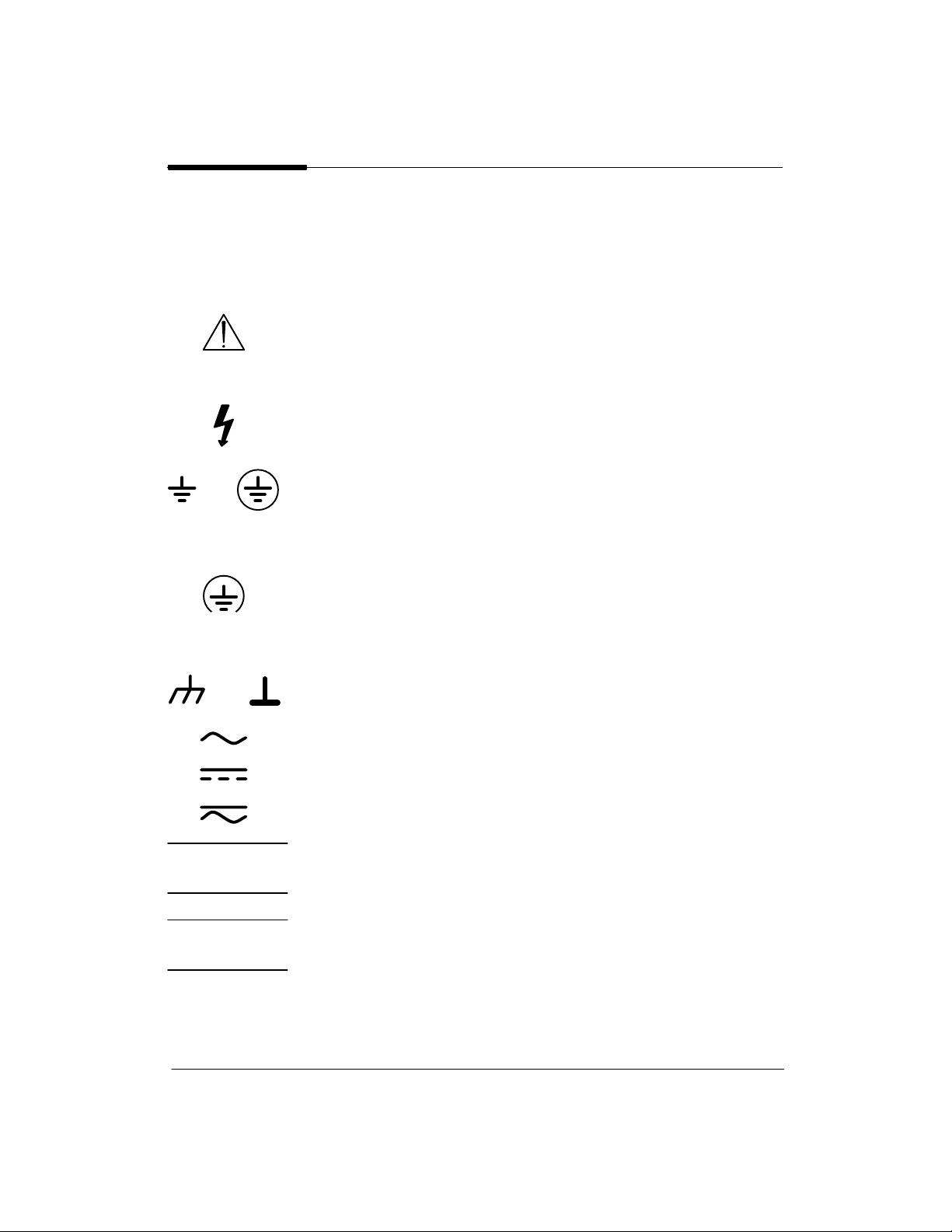
General Definitions of Safety Symbols
International caution symbol (refer to manual): the product will be
marked with this symbol when it is necessary for the user to refer
to the instruction manual in order to protect against damage to the
instrument.
Indicates dangerous voltage (terminals fed from the interior by
voltage exceeding 1000 volts must also be marked).
Protective conductor terminal. For protection against electrical
shock in case of a fault. Used with field wiring terminals to indi–
cate the terminal which must be connected to ground before
operating equipment.
Low–noise or noiseless, clean ground (earth) terminal. Used for a
signal common, as well as providing protection against electrical
shock in case of a fault. A terminal marked with this symbol must
be connected to ground in the manner described in the installation
(operating) manual, and before operating the equipment.
Frame or chassis terminal. A connection to the frame (chassis) of
the equipment which normally includes all exposed metal.
Alternating current
Direct current
Alternating or direct current
The WARNING sign denotes a hazard. It calls attention to a pro–
cedure, practice, or the like, which, if not correctly performed or
adhered to, could result in personal injury.
The CAUTION sign denotes a hazard. It calls attention to an op–
erating procedure, practice, or the like, which if not correctly
performed or adhered to, could result in damage to or destruction
of part or all of the product.

Chapter 1 Product Information
1-1Product Information
INTRODUCTION
This chapter contains a listing of documentation supplied with the HP C2858A and C2859A
DesignJet 650C plotters. Also provided are: descriptions of the plotters, information on the
plotter features, options and accessories, performance characteristics, and plotter serial
number information.
Introduction 1-1. . . . . . . . . . . . . . . . . . . . . . . . . . . . . . . . . . . . . . . . . . . . . . . . . . . . . . .
Description 1-2. . . . . . . . . . . . . . . . . . . . . . . . . . . . . . . . . . . . . . . . . . . . . . . . . . . . . . . .
Options 1-4. . . . . . . . . . . . . . . . . . . . . . . . . . . . . . . . . . . . . . . . . . . . . . . . . . . . . . . . . . .
Plug-in Memory 1-4. . . . . . . . . . . . . . . . . . . . . . . . . . . . . . . . . . . . . . . . . . . . . . . .
ROM Enhancement Modules 1-4. . . . . . . . . . . . . . . . . . . . . . . . . . . . . . . . . . . . . .
Modular Input/Output (MIO) PCAs 1-4. . . . . . . . . . . . . . . . . . . . . . . . . . . . . . . . .
Accessories 1-5. . . . . . . . . . . . . . . . . . . . . . . . . . . . . . . . . . . . . . . . . . . . . . . . . . . . . . .
Performance Characteristics 1-6. . . . . . . . . . . . . . . . . . . . . . . . . . . . . . . . . . . . . . . . . .
Serial Number Information 1-6. . . . . . . . . . . . . . . . . . . . . . . . . . . . . . . . . . . . . . . . . . .

1-2 Product Information
DESCRIPTION
HP C2858A and C2859A DesignJet 650C plotters provide graphic displays of computer pro-
gram output data. They operate with a number of computer systems and graphic terminals,
using either RS-232-C or Centronics external controllers. With one of several optional, mod-
ular input/output (MIO) cards installed, the plotter can operate: with an HP-IB external con-
troller, within a Novell Ethernet or Token ring network, as a TCP/IP host workstation, with a
LAN Manager, with Ethertalk and with Apple LocalTalk.
The C2858/9A DesignJet 650C plotters will accept drawing data from Computer Aided De-
sign (CAD) software programs supporting the HP-GL (vector), the HP-GL/2 (vector), HP
RTL (raster), and PJL languages. HP-GL/2 is available with Kanji character sets when the
Kanji ROM SIMM is installed. Postscript is also available when the PostScript ROM SIMM
upgrade is installed.
The HP C2858/9A DesignJet 650C plotters (see Figure 1-1) are large-format, color and
monochrome, ink-jet plotters designed to plot monochrome plots on commonly available
opaque bond paper, translucent (Japanese tracing) paper, vellum, or special inkjet-compat-
ible drafting film. Quality color output is only supported when using HP special inkjet paper.
C2858/9A DesignJet 650C plotters can produce plots on single-sheet media or roll-feed me-
dia. Large format plots of high resolution and quality are generated for applications such as
computer aided design (CAD), computer aided manufacturing (CAM), mapping, mechani-
cal and architectural drawings, and general drafting.
Five high-capacity ink cartridges are provided with the C2858/9A plotters. Selectable pen-
width settings are modified to ISO standard pen widths. The cartridges simultaneously scan
across the media providing 300 dpi resolution in draft and final modes, 300 dpi addressable
resolution for color in enhanced mode and 600 dpi addressable resolution for monochrome in
enhanced mode.
C2858A plotters can plot on media sizes ranging from International Standards Organization
(ISO) sizes A1 through A4, American National Standards (ANSI) sizes A through D, and
architectural media sizes C and D. Model C2859A plotters can plot on media sizes ranging
from International Standards Organization (ISO) sizes A0 through A4, American National
Standards (ANSI) sizes A through E, and architectural media sizes C through E. Roll-feed
capability allows the plotters to perform long-axis plotting in lengths up to 50 feet.
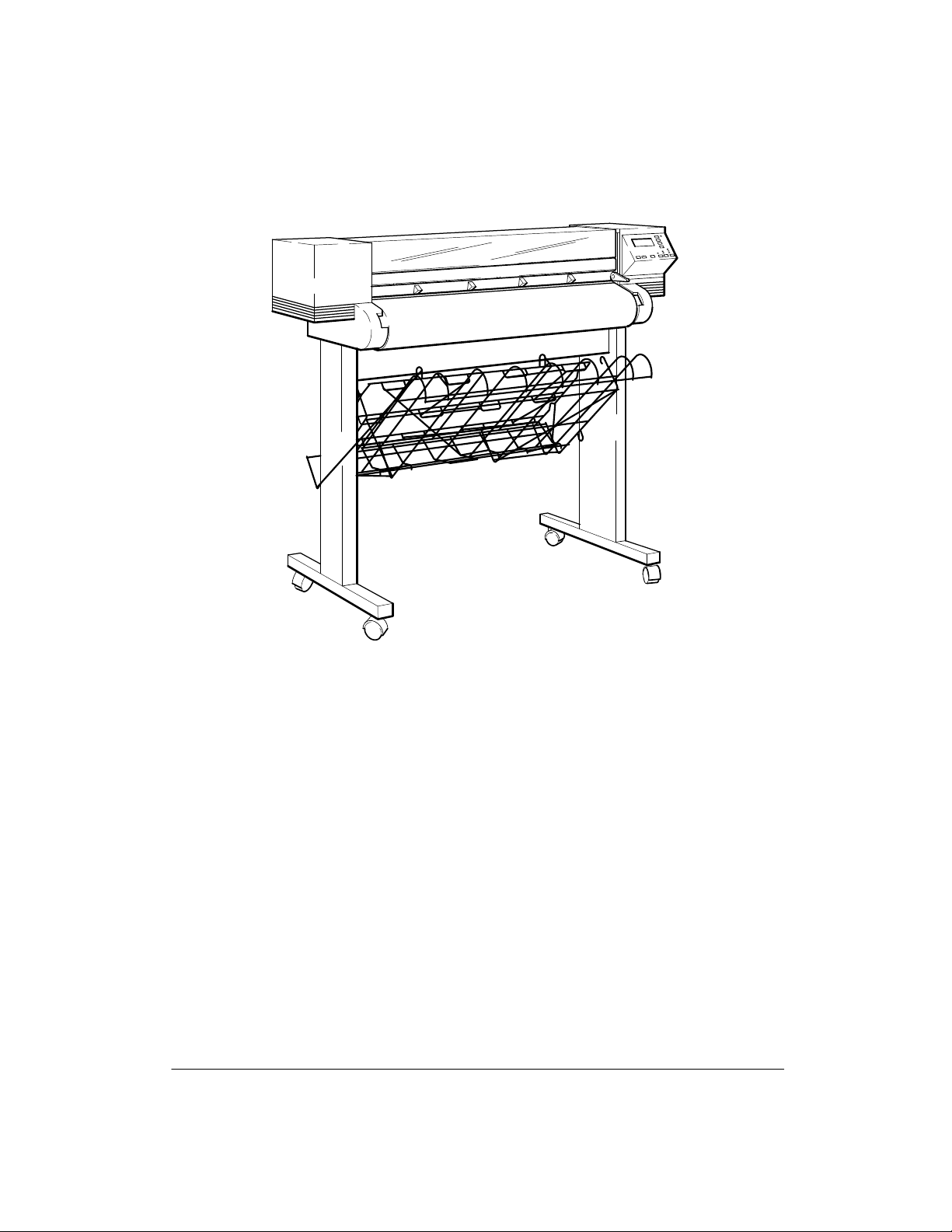
1-3Product Information
Figure 1-1.
The standard HP C2858/9A DesignJet 650C has four megabytes of on-board random access
memory (RAM). Memory expansion upgrades to 20 MB are available as well as various
ROM enhancement and modular I/O options. Other features that are standard include:
Automatic media edge sensing
Automatic pen alignment, testing and servicing
Automatic media stacking with adjustable media bin
An automatic, single-axis cutter
Queueing, nesting and expanded margin capabilities
Easy-to-read 2 row by 20 character vacuum fluorescent display (VFD)
Built-in diagnostic and demonstration plot routines

1-4 Product Information
OPTIONS
PLUG-IN MEMORY
C2858/9A DesignJet 650C plotters have two memory expansion sockets. Each can hold ei-
ther a four-megabyte or eight-megabyte, Single In-line Memory Module (SIMM). There-
fore, memory can be expanded by 4, 8, 12 or 16 megabytes. The SIMM part numbers are:
Four Mbyte SIMM = P/N C2065A
Eight Mbyte SIMM = P/N C2066A
ROM ENHANCEMENT MODULES
Two ROM expansion sockets are also provided in the C2858/9A DesignJet 650C plotters.
Each will hold a single ROM enhancement SIMM. The ROM SIMMS could include firm-
ware revision upgrades or language enhancements. A Kanji ROM SIMM is available for Jap-
anese users who require the Kanji character sets. A PostScript upgrade is also available in
ROM SIMM. The part numbers for the kits are:
Kanji ROM Kit = P/N C2847-60031
PostScript ROM Kit = P/N C2882A
MODULAR INPUT/OUTPUT (MIO) PCAs
Interface circuitry is provided on the plotters which allows the user to install HP supported
modular I/O (MIO) cards for several interface applications. Although multiple protocols
may reside on an MIO, they are not simultaneously supported, only one protocol at at time
can be used. The MIO card part numbers are:
Multi-protocol Ethernet for Novell, TCP/IP, LAN Manager, Ethertalk
with RJ-45 (twisted pair) and BNC (ThinLAN) connectors) = P/N J2372A
with RJ-45 (twisted pair) connector only = P/N J2371A
Multi-protocol Token Ring for Novell, LAN Manager = P/N J2373A
HP-IB = P/N C1642A
Apple LocalTalk = P/N J2341A

1-5Product Information
ACCESSORIES
The items listed in Table 1-1 are supplied with each plotter. Miscellaneous application notes,
flyers and driver disks are also provided. Depending upon the country of destination, the part
numbers of items listed as English or U.S. will differ. Accessories available for use with the
C2858/9A DesignJet 650C plotters are listed in the Supplies Catalog.
Table 1-1. Accessories Supplied
Description
Qty HP Part Number
C2858A/C2859A Manual Kit (English)
includes: Using Your Plotter’s Front Panel
Guide, Setting Up For Plotting Guide, and
Quick Reference Guide
1 C2858–90051
Power Cord (U.S.) 1 8120–1378
Media Sampler Roll (CX Jet Series)
24ºx150’ C2858A
36ºx150’ C2859A
1
1
51631D
51631E
Pens: Black
Cyan
Magenta
Yellow
2
1
1
1
51640A
51650C
51650M
51650Y
Hardware Kit 1 C2847–60061
Cable Management Hardware Kit 1 C2847-60030
Front Panel Overlay (English) 1 C2858–60026
Guide/Cutter Holder 1 C1633–40094
Manual Cutter 1 17291C
Supplies Catalog 1 5091–3485EUS
Supplies Catalog Update 1 5091–6787EUS
Unpackaging Instructions 1 C2858–90003
Spindle Assembly: C2858A
C2859A
1
1
C2847-60033
07596-60060
Spindle Flange 1 07596-40076
Spindle Spacer 1 07596-40077

1-6 Product Information
PERFORMANCE CHARACTERISTICS
Table 1-2 lists the performance characteristics of the plotters.
Table 1-2. Performance Characteristics
Accuracy
0.38 mm (0.015 in.) or 0.2% of the specified vector length, whichever is
greater at 23 C (73 F) at 50-60% RH, on HP film (monochrome mode only).
Throughput
D-sized loaded vertically: plain paper special paper special paper
monochrome monochrome color
Draft mode 1.8 min. 1.8 min. 3.4 min.
Final mode 3.2 min. 2.7 min. 4.3 min.
Enhanced mode 6.5 min. 6.5 min. 8.7 min.
Resolution
Draft Mode 300 dpi addressable
Final Mode 300 dpi addressable
Enhanced Mode 300 dpi addressable (color)
600 dpi addressable (monochrome)
Margins
Leading and Trailing 17 mm ( 2mm) (normal plot area),
10 mm (expanded plot area)
Sides 5 mm (normal or expanded plot area)
Media Dimensions
Sheet and Roll
Maximum Widths D (A1)-size 619 mm (24 in.)
E (A0)-size 917 mm (36 in.)
Roll
Maximum Media Length 150 feet (125 ft. for film)
SERIAL NUMBER INFORMATION
If the plotter serial number has a lower revision letter than the one shown on the title page,
information in the Product History chapter, Chapter 9, will adapt this manual to that plotter.

Chapter 2 Site Planning and Requirements
2-1Site Planning and Requirements
INTRODUCTION
This chapter contains information concerning the electrical requirements for the installation
of HP C2858A and C2859A plotters. Also included is information on environmental operat-
ing conditions and physical specifications for the plotters.
Introduction 2-1. . . . . . . . . . . . . . . . . . . . . . . . . . . . . . . . . . . . . . . . . . . . . . . . . . . . . . .
Electrical Specifications 2-2. . . . . . . . . . . . . . . . . . . . . . . . . . . . . . . . . . . . . . . . . . . . .
Power Requirements 2-2. . . . . . . . . . . . . . . . . . . . . . . . . . . . . . . . . . . . . . . . . . . . .
Line Cord Set 2-2. . . . . . . . . . . . . . . . . . . . . . . . . . . . . . . . . . . . . . . . . . . . . . . . . .
Environmental Specifications 2-3. . . . . . . . . . . . . . . . . . . . . . . . . . . . . . . . . . . . . . . . .
Physical Specifications 2-3. . . . . . . . . . . . . . . . . . . . . . . . . . . . . . . . . . . . . . . . . . . . . .
Cable Restrictions 2-4. . . . . . . . . . . . . . . . . . . . . . . . . . . . . . . . . . . . . . . . . . . . . . . . . .
RS-232-C Interface 2-4. . . . . . . . . . . . . . . . . . . . . . . . . . . . . . . . . . . . . . . . . . . . . .
Centronics Interface 2-4. . . . . . . . . . . . . . . . . . . . . . . . . . . . . . . . . . . . . . . . . . . . .
HP-IB Interface 2-4. . . . . . . . . . . . . . . . . . . . . . . . . . . . . . . . . . . . . . . . . . . . . . . . .

2-2 Site Planning and Requirements
ELECTRICAL SPECIFICATIONS
POWER REQUIREMENTS
HP C2858A and C2859A DesignJet 650C plotters have self-adjusting power supplies and do
not require voltage selector or switch settings prior to use. Table 2-1 lists the power require-
ments for the plotters.
Table 2-1. Power Requirements
Voltage Requirements
Frequency
Source
Voltage Current (max)
100 Vac 1.4 A
120 Vac 1.2 A
220 Vac 650 mA
240 Vac 600 mA
47-53 Hz and 57-63 Hz
Consumption 140 Watts maximum
LINE CORD SET
W A R N I N G
The configuration of the ac line cord set required for use with the plotters is determined by the
country of destination for the plotters. Refer to Chapter 3 for a listing of the available ac line
cord connectors.

2-3Site Planning and Requirements
ENVIRONMENTAL SPECIFICATIONS
Table 2-2 lists environmental specifications for the plotters.
Table 2-2. Environmental Specifications
Temperature
Storage
Operating
Optimal Operating
–40 to +70 C (–40 to +158 F)
0 to +55 C (+32 to +131 F)
+15 to +30 C (+59 to +86 F)
Relative Humidity (Operating) 20 to 80 % RH
PHYSICAL SPECIFICATIONS
The plotter physical specifications are listed in Table 2-3.
Table 2-3. Physical Specifications
Length
Depth
Height
Weight
Packaging:
Plotter Body
Length
Width
Height
Weight
Leg Pack
Length
Width
Height
Weight
C2858A C2859A
1092 mm (43 in) 1372 mm (54 in)
711 mm (28 in) 711 mm (28 in)
1169 mm (46 in) 1219 mm (48 in)
58 kg (128 lbs) 70 kg (155 lbs)
1270 mm (50 in) 1574 mm (62 in)
584 mm (23 in) 584 mm (23 in)
635 mm (25 in) 635 mm (25 in)
68 kg (150 lbs) 68 kg (150 lbs)
940 mm (37 in_ 1219 mm (48 in)
711 mm (28 in) 762 mm (30 in)
229 mm (9 in) 229 mm (9 in)
21 kg (45 lbs) 25 kg (55 lbs)

2-4 Site Planning and Requirements
CABLE RESTRICTIONS
Cable restrictions for the plotter are determined by the type of interface being used. Recom-
mendations for each interface are supplied in the following paragraphs.
RS-232-C INTERFACE
The use of short cables (each less than 15 metres or 50 feet) is recommended for the
RS-232-C Interface. Longer cables are permissible, provided the load capacitance does not
exceed 2500 picofarads.
CENTRONICS INTERFACE
The use of short cables (each less than 2 metres or 6.6 feet) is recommended for the Centron-
ics Interface.
HP-IB INTERFACE
The HP-IB (Hewlett-Packard Interface Bus) allows up to 15 devices to be connected. The
maximum cable length is restricted to 2 metres (6.6 ft.) per device up to a total of 20 metres
(65.8 ft.). The devices may be connected in a star or linear bus network.

Chapter 3 Installation and Configuration
3-1Installation and Configuration
INTRODUCTION
This chapter contains the information required to configure and verify proper operation of
the HP C2858A and C2859A DesignJet 650C plotters. Print cartridge and media loading pro-
cedures, as well as front panel menu structures, are also provided.
Introduction 3-1. . . . . . . . . . . . . . . . . . . . . . . . . . . . . . . . . . . . . . . . . . . . . . . . . . . . . . .
Installation Instructions 3-2. . . . . . . . . . . . . . . . . . . . . . . . . . . . . . . . . . . . . . . . . . . . . .
User-Installable Modules 3-2. . . . . . . . . . . . . . . . . . . . . . . . . . . . . . . . . . . . . . . . .
Connectivity 3-2. . . . . . . . . . . . . . . . . . . . . . . . . . . . . . . . . . . . . . . . . . . . . . . . . . .
Line Voltage and Fusing 3-2. . . . . . . . . . . . . . . . . . . . . . . . . . . . . . . . . . . . . . . . . .
Power Cord Configurations 3-2. . . . . . . . . . . . . . . . . . . . . . . . . . . . . . . . . . . . . . . .
User Information and Operation 3-4. . . . . . . . . . . . . . . . . . . . . . . . . . . . . . . . . . . . . . .
Media Guidelines 3-4. . . . . . . . . . . . . . . . . . . . . . . . . . . . . . . . . . . . . . . . . . . . . . .
Media Type and Print Quality 3-4. . . . . . . . . . . . . . . . . . . . . . . . . . . . . . . . . . . . . .
Media Cutting and Stacking 3-5. . . . . . . . . . . . . . . . . . . . . . . . . . . . . . . . . . . . . . .
Usable Media Sizes 3-6. . . . . . . . . . . . . . . . . . . . . . . . . . . . . . . . . . . . . . . . . . . . . .
Loading Roll Media 3-6. . . . . . . . . . . . . . . . . . . . . . . . . . . . . . . . . . . . . . . . . . . . .
Unloading Roll Media 3-10. . . . . . . . . . . . . . . . . . . . . . . . . . . . . . . . . . . . . . . . . . . .
Loading Sheet Media 3-11. . . . . . . . . . . . . . . . . . . . . . . . . . . . . . . . . . . . . . . . . . . .
Unloading Sheet Media 3-12. . . . . . . . . . . . . . . . . . . . . . . . . . . . . . . . . . . . . . . . . . .
Clearing Media Jams 3-12. . . . . . . . . . . . . . . . . . . . . . . . . . . . . . . . . . . . . . . . . . . . .
Pen Checking 3-13. . . . . . . . . . . . . . . . . . . . . . . . . . . . . . . . . . . . . . . . . . . . . . . . . . .
Accessing Pens 3-14. . . . . . . . . . . . . . . . . . . . . . . . . . . . . . . . . . . . . . . . . . . . . . . . .
Replacing Pens 3-14. . . . . . . . . . . . . . . . . . . . . . . . . . . . . . . . . . . . . . . . . . . . . . . . .
Selectable Ink-Drying Times 3-16. . . . . . . . . . . . . . . . . . . . . . . . . . . . . . . . . . . . . . .
Configuration 3-17. . . . . . . . . . . . . . . . . . . . . . . . . . . . . . . . . . . . . . . . . . . . . . . . . . . . . .
Front Panel Controls 3-17. . . . . . . . . . . . . . . . . . . . . . . . . . . . . . . . . . . . . . . . . . . . .
Front Panel Menus 3-20. . . . . . . . . . . . . . . . . . . . . . . . . . . . . . . . . . . . . . . . . . . . . .
Front Panel Languages 3-21. . . . . . . . . . . . . . . . . . . . . . . . . . . . . . . . . . . . . . . . . . .
Front Panel Messages 3-22. . . . . . . . . . . . . . . . . . . . . . . . . . . . . . . . . . . . . . . . . . . .
Operational Verification 3-26. . . . . . . . . . . . . . . . . . . . . . . . . . . . . . . . . . . . . . . . . . . . . .
Power-On Self-Test 3-26. . . . . . . . . . . . . . . . . . . . . . . . . . . . . . . . . . . . . . . . . . . . . .
Demonstration Plot 3-26. . . . . . . . . . . . . . . . . . . . . . . . . . . . . . . . . . . . . . . . . . . . . .

3-2 Installation and Configuration
INSTALLATION INSTRUCTIONS
USER-INSTALLABLE MODULES
Expansion sockets located behind a panel at the rear of the plotter allow the user to install
additional memory modules. These SIMMs (single in–-line memory modules) are available
in 4MB and 8MB sizes. Installation is accomplished by removing the access panel (4
screws), installing the module(s), and reattaching the access panel. ROM sockets are also
provided for use with ROM enhancements as developed. Installation instructions are pro-
vided with the modules and also provided in Chapter 6 of this manual. Information on order-
ing the memory expansion and ROM modules is provided in Chapter 1 of this manual.
An interface port on the back of the plotter allows the user to select one of several available
modular interfaces at a time. The modular I/O cards can be easily changed to match the de-
sired application. Installation instructions are provided with the modules and also provided
in Chapter 6 of this manual. Information on ordering the modular I/Os is provided in Chapter
1 of this manual.
CONNECTIVITY
Depending upon the interface and hardware being used to drive the plotters, different cables
could be required. A listing of cables and other connectivity related issues is provided in the
DesignJet 650C documentation listed in Chapter 1 of this manual.
LINE VOLTAGE AND FUSING
The HP C2858/9A DesignJet 650C plotter ’s power supply automatically adjusts to the input
voltage. The plotter’s autoranging power supply accepts an input of 90 to 264 Vac.
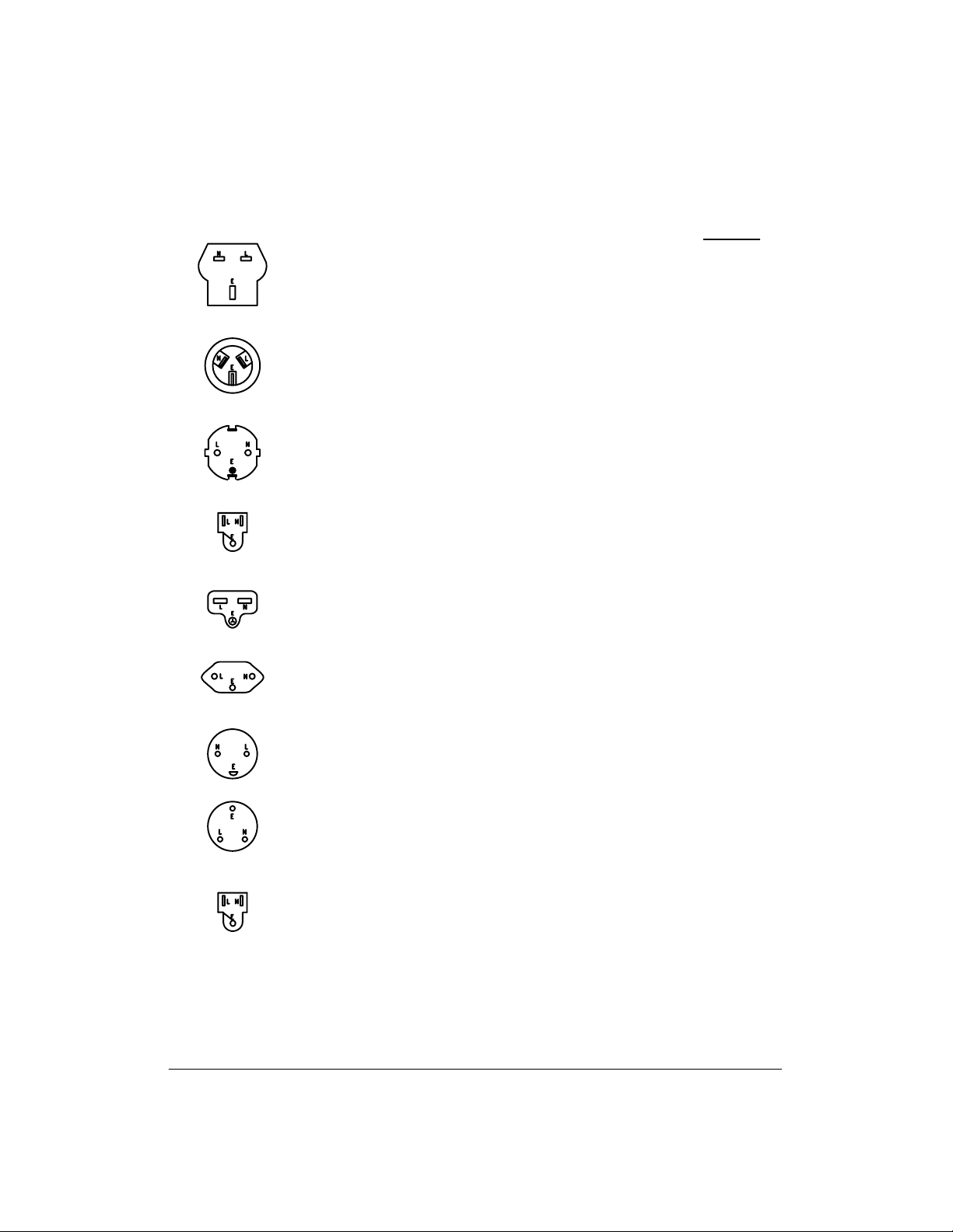
POWER CORD CONFIGURATIONS
Power cord configurations shipped with the plotter depend upon the country of destination
for the plotter. See Figure 3-1 for information on the power cord configurations available for
use with the plotters. When connecting the plotter to the ac source, ensure that the appropriate
power cord is used.
3-3Installation and Configuration
Figure 3-1.
BS 1363A
AS C112
CEE 7–VII
NEMA 5–15P
NEMA 6–15P
SEV 1011
DHCK–107
Option No.
900
901
902
903
904
906
912
917
N = Neutral or Identified Conductor
E = Earth or Safety Ground
918
NOTE:
L = Line or Active Conductor (also called ªliveº or ªhotº)
MITI 41–9692
All plugs are viewed from the power outlet connector end.
250 Vac, 13 A, Single Phase plug rating.
For use in United Kingdom, Cypress,
Nigeria, Zimbabwe, Singapore.
250 Vac, 10/16 A, Single Phase plug rating.
For use in East and West Europe, Egypt.
125 Vac, 15 A, Single Phase plug rating.
For use in Canada, Mexico, Philippines,
Taiwan, Saudi Arabia, UL approved in the
United States
250 Vac, 10 A, Single Phase plug rating.
For use in Switzerland.
250 Vac, 10 A, Single Phase plug rating.
For use in Denmark.
250 Vac, 10 A, Single Phase plug rating.
For use in India, Republic of South Africa.
250 Vac, 10 A, Single Phase plug rating.
For use in Australia, New Zealand.
250 Vac, 15 A, Single Phase plug rating.
For use in Canada, UL approved in the
United States.
125 Vac, 12 A, Single Phase plug rating.
For use in Japan.

3-4 Installation and Configuration
USER INFORMATION AND OPERATION
MEDIA GUIDELINES
Guidelines on media handling are:
The leading edge must be straight and each side must be loaded evenly. If the
leading edge is jagged, trim it with the media knife (located in the manual holder at
the back of the plotter) using the track on top of the plotter as a guide.
If media is curled, load it with the curl up. The exception to this is film media,
which must always be loaded with the plotting side (matte side) down.
Roll media must be flush with the right edge of the core.
Film should be handled by the edges or when wearing cotton gloves. Load film
with the matte side down (shiny side up).
MEDIA TYPE AND PRINT QUALITY
DesignJet 650C plotters have several combinations of plotting modes. Each mode is depen-
dent upon the color/monochrome setting, media type, and print quality settings input through
the front panel. Interaction between the settings produces the ten modes. Each mode has a
unique combination of print resolution, number of passes and resultant ink-drying time.
Media Type is set through the front panel when media is loaded into the plotter. The front
panel display prompts the user to select for sheet or roll loading and then to scroll through the
menu and select for one of the five media types listed below. The menu selection should be set
to match the media type being used.
Opaque bond (paper)
Film
Special paper
Vellum
Translucent
A front panel button allows you to plot in one of three Plot Quality modes. Continuous press-
ing of the button toggles through the modes and the associated LEDs are lit indicating the
current print quality mode selection. The Plot Quality modes are:
Draft
Final
Enhanced

3-5Installation and Configuration
Real-time switching between plotting modes is not supported. If the user selects another
mode while plotting, the plotter waits until the current plot is finished and then switches to the
newly selected mode.
MEDIA CUTTING AND STACKING
Automatic and manual cutting of plots is available on the C2858/9A. In roll media opera-
tions, the user can choose between continuous plotting or cutting plots off the roll automati-
cally as they are completed.
Automatic cutting When roll media is loaded, whether or not queueing is
ON, the plotter automatically cuts plots and drops them
into the media bin. When queueing and nesting are ON,
the plotter cuts each nest. The automatic cutter can be
programmatically disabled. When cutting is disabled, the
plotter draws tick marks at the plot margins to indicate
the end of a plot or nest. The automatic cutter can be
enabled programmatically or by cycling power.
Manual cutting The front panel Form Feed/Cut button can be used to
feed the media out and cut it after a plot is completed.
Media stacking Unattended stacking of cut sheets is provided by the
adjustable media bin. The user must adjust the movable
shelf of the bin according to the length of the cut sheets.
Bin capacity is 20 sheets.
Manual cutter A manual cutter is provided with the plotter for hand-
cutting of media and is stored in the manual holder on
the back of the plotter.

3-6 Installation and Configuration
USABLE MEDIA SIZES
Media of different types and sizes can be used on the plotters. Refer to Table 3-1 for the media
sizes usable on each plotter.
Table 3-1. Media Sizes
C2858A
C2859A
ISO A4 - A1 ISO A4 - A0
ANSI A - D ANSI A - E
ARCH A - D ARCH A - E
JIS B4 - B2 JIS B4 - B1
Oversize A2 Oversize A1
24 in. Wide Roll 24 in. Wide Roll
36 in. Wide Roll
LOADING ROLL MEDIA
If the spindle is already loaded into the plotter, remove the spindle by opening the roll cover
and pulling on both ends of the spindle to remove it from the plotter. To load roll media into
the plotter, put a roll of media on the plotter spindle and insert the spindle in the plotter by
performing the following steps:
W A R N I N G
Be sure that the plotter wheels are locked to prevent
the plotter from moving while loading roll media. To
lock the wheels, press the locking levers on the wheels
to the down position.
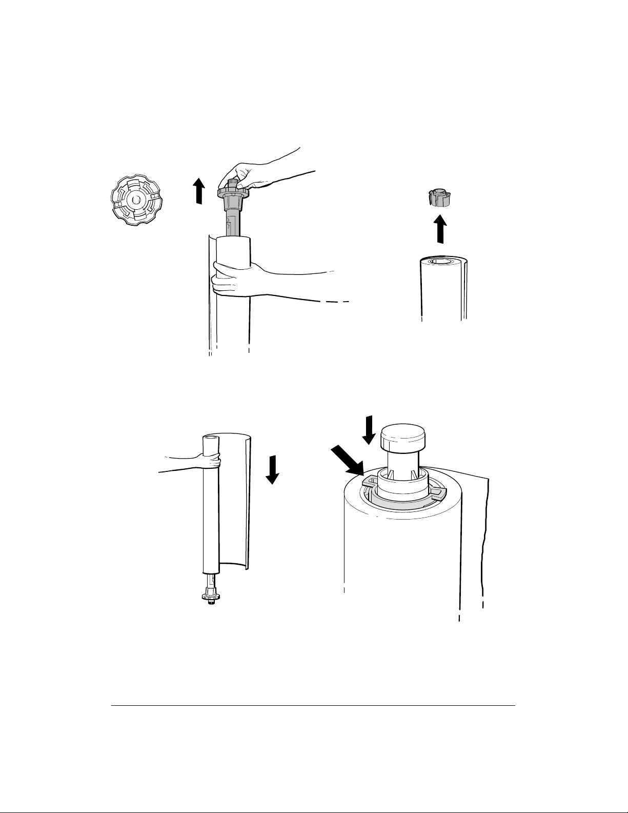
1. Standing the spindle on the end opposite the large, scalloped media stop, pull the
scalloped media stop to release the spindle from the used roll. Set the spindle aside.
Turn the used roll over and slip the endcap out with your finger. See Figure 3-2.
2. Slide the roll onto the spindle with the leading edge winding clockwise. Push the
endcap into the media core, making sure the tabs are flush against the edge of the
roll. See Figure 3-3.
3-7Installation and Configuration
Figure 3-2.
Removing the Media Stop and Endcap
(C) C2847-10(UM)
Figure 3-3.
Sliding the New Roll onto the Spindle
(C) C2847-16(UM)
3-8 Installation and Configuration
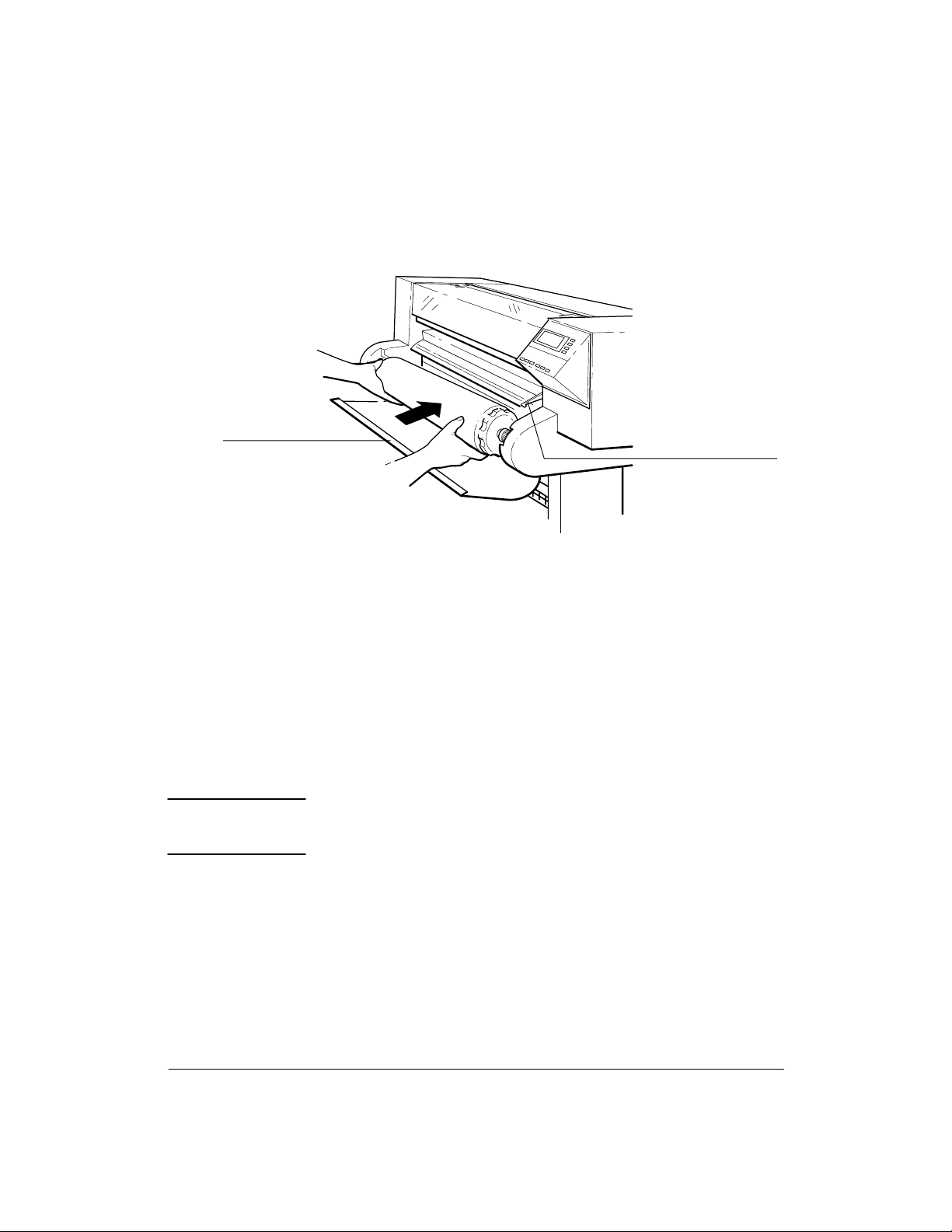
3. Open the roll cover and insert the spindle, with the endcap at the left and the media
stop at the right. Firmly push on both ends. See Figure 3-4.
Figure 3-4.
Roll Cover
Pinchwheel Lever
Installing the Spindle
(C) C2847-31(UM)
4. Once the roll is in place, push the media all the way to the right, so that it’s flush
against the media stop.
5. Ensure that the pinchwheel lever at the right of the plotter is down.
6. Turn the plotter ON, if it is not already ON.
7. Grasp the leading edge of the media and pull about one foot (30 cm) of media out
from the roll. Check the leading edge of the media. If it appears uneven, or to ensure
a straight edge, the edge will need to be trimmed.
W A R N I N G
The cutter blade is very sharp. Use caution when using the
cutter to trim or cut media. Keep hands away from the blade
when cutting. Retract the blade into the cutter after use.
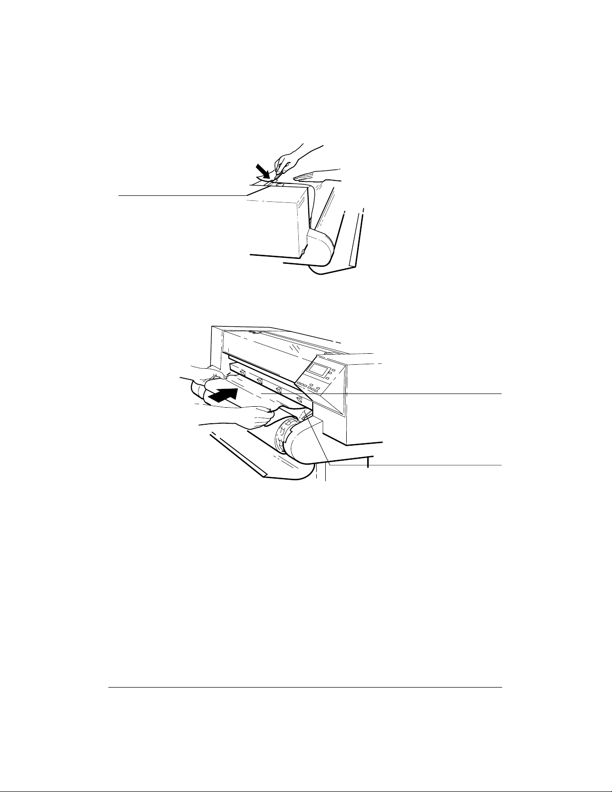
8. Trim the leading edge if it’s uneven. Pull it over the top of the plotter and lay it over
the cutting track. Using the cutter located in the holder at the back of the plotter, cut
off the first few inches of the media. See Figure 3-5. Return the cutter to the holder.
9. Load the leading edge, aligning the right edge with the perforated line on the entry
platen. Push the media in until it buckles slightly as it hits the stops inside the plotter.
Let go when the plotter begins to pull the media in. See Figure 3-6.
3-9Installation and Configuration
Figure 3-5.
Cutting Track
Trimming the Leading Edge of the Media
(C) C2847-7(UM)
Figure 3-6.
Align Media with
Perforation Line
Insert Media Until
it Buckles Evenly
Loading the Leading Edge of the Media
(C) C2847-15(UM)
10. When the front panel displays ªSheet load/Roll load,º press the Down Arrow
button to select ªRoll load.º
11. When the front panel displays ªSELECT MEDIA,º press the Up or Down Arrow
button to scroll through and select the media choice. Press the Enter button to set the
plotter for the media type being used. The plotter will now load the roll of media.
12. When indicated on the front panel, raise the pinchwheel lever to the up position.
13. When ªPull
/ Align edges to rollº is displayed on the front panel, pull the left
and right edges of the roll toward you until taut. Then align the left and right edges of
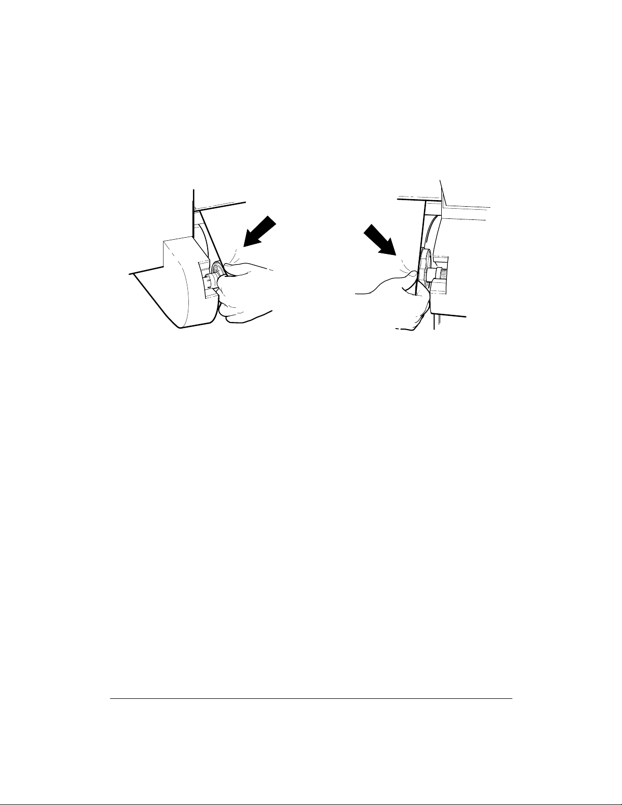
3-10 Installation and Configuration
the media so that they are flush with the left and right edges of the roll. See
Figure 3-7.
Figure 3-7.
Aligning the Left and Right Edges of the Media
(C) C2847-97(UM)
(C) C2847-97a(UM)
14. When the front panel instructs you, lower the pinchwheel lever. The plotter checks
to make sure the roll is properly aligned.
15. When ªClose roll cover/Continue
º is displayed, rewind the media stop to take up
any slack in the roll. Make sure the leading edge of the media is outside the roll cov-
er, then close the roll cover. Press the Down Arrow button to continue. The plotter
trims off the first few inches of media. When roll loading is complete, the ªSTATUS
Ready to plotº message is displayed.
UNLOADING ROLL MEDIA
To unload roll media from the platen without removing the spindle from the plotter, do the
following steps:
1. Raise the pinchwheel lever to the up position.
2. Open the roll cover and turn the media stop to wind the media back onto the spindle.
3. Close the roll cover.
4. Lower the pinchwheel lever to the down position.
To remove the spindle with roll media, perform steps 1 and 2 above, then pull on both ends of
the spindle to remove it from the plotter.
 Loading...