


Designjet 3D Removal System
Table of contents
 Loading...
HP Designjet 3D Removal System
Service Guide
Legal Notice
© 2012 Hewlett-Packard Development
Company, L.P.
The information contained herein is subject
to change without notice.
The only warranties for HP Products and services
are set forth in the express warranty statement
accompanying such products and services.
Nothing herein should be construed as
constituting an additional warranty.
HP shall not be liable for technical or editorial
errors or omissions contained herein.
.
Conforms to ANSI/UL std. 60950-1-2003
Certified to CAN/CSA C22.2 no. 60950-1-03
HP Designjet 3D Removal System
conform with the following standards, in accordance with the
EU Machinery, Low Voltage and Electromagnetic
Compatibility Directives.

3
Introduction
The HP Designjet 3D Removal System is specifically developed to provide
efficient removal of support material from a model. The system removes sup-
port material by immersing models in a bath of water with a specific amount
of cleaning agent bags added to the cleaning agent receptacle.
Welcome to the new dimension of HP Designjet 3D Removal System!
How to use this guide
This Service Guide is laid out in easy to follow sections that cover Set-up,
Operation, Maintenance, and Troubleshooting. Read each section carefully
so that you will get the best performance from your HP Designjet 3D
Removal System.
4
Safety
The following classifications are used throughout this guide.
CAUTION: Indicates a potentially hazardous situation
which, if not avoided, may result in minor or
moderate injury.
WARNING: Indicates a potentially hazardous situation
which, if not avoided, could result in serious injury.
Recycle: Use proper recycling techniques for materials and
packaging.
ESD: Use standard electrostatic
discharge (ESD) precautions
when working on or near
electrical components.

5
Table of Contents
Introduction
How to use this guide .....................................................................page 3
Safety ............................................................................................page 4
<> <>
System Overview
How the system works ...................................................................page 7
Setup
Connecting the system ....................................................................page 9
Operation
Cleaning Models ..........................................................................page 11
Other information ........................................................................page 15
Maintenance
Inspecting and cleaning the strainer ..............................................page 17
Cleaning .................................................................................... ..page 17
Model bag ...................................................................................page 17
Troubleshooting
Troubleshooting ...........................................................................page 19
Non-Coded Error Conditions ..........................................................page 19
Error Detection .............................................................................. page 21
Diagnostic and Test Specifications ................................................. page 25
Functional Description ....................................................................page 25
Subtest details ...............................................................................page 29
Service Procedures
Maintenance Preparation .............................................................page 32
Cabinet Components ....................... ....... ....... ....... ....... ........ ......... page 34

6
System Lid ....................................................................................page 34
Lower Housing Assembly ................................................................page 36
Upper Housing Assembly ............................................................... page 38
Hardware Components ................................................................page 39
Back Panel ...................................................................................page 39
Line Filter ......................................................................................page 44
Thermostat .................................................................................... page 45
Thermometer Board ....................................................................... page 47
User Interface Board ...................................................................... page 49
Power Entry Module ......................................................................page 52
Main Control Board .......................................................................page 54
Cleaning Tank Assembly ................................................................page 60
Agitation Assembly ........................................................................page 65
Drive Belt .....................................................................................page 68
Induction Motor Assembly ..............................................................page 70
Float Level Sensor Assembly ...........................................................page 72
Lid Switch Assembly ......................................................................page 74
Lid Lock Assembly .........................................................................page 76
Appendix
System Components .....................................................................page 80
Upper Components ......................................................................page 81
Internal Components .................................................................. ..page 82
7
System Overvie w
How the system works
The system removes support material by immersing models in a bath of
water with a specific amount of cleaning agent bags added to the cleaning
agent receptacle. The system heats and circulates solution around the models
in the cleaning tank. The solution dissolves the support material without
harming the underlying model material. Over time, depending on geometry
and the amount of support material, all the support material is dissolved and
the models are ready to be removed, dried and used for their intended pur-
pose.
The system incorporates the following functions:
•Automatic water fill
• User selectable cleaning tank level (half or full)
• Automatic water drain
• Automatic timing device for user selectable short, medium, or long cycles
• Automatic lock/unlock before and after cycling
• Automatic rinse and drain cycle
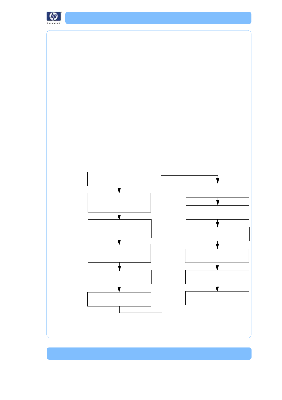
Figure 1: Sequence of Operation
Place model(s) in model basket
Select:
Cleaning tank level
Cycle length
Lid locks
Drain
Rinse cycle
Drain
Lid unlocks
Remove model(s)
Power on the System
Pour in all the contents of the
cleaning agent bag(s)
Press start cycle button
Wash cycle

8

9
Setup
Connec ting the system
Make sure the following preparations of the physical site are met:
• The system must be placed on a flat and stable surface able to support
36 kg (80 lbs.) to avoid the risk of falling.
• The work area for unpacking the system should be 76.2 cm (30 in.) high,
76.39 cm (28.5 in.) wide and 69.95 cm (27 in.) deep.
• The system must be located at least 20 cm (8 in.) higher than the waste-
water drain.
• The drain facility must accept a drain pH level between 6.5 and 10.0.
• The drain must accept a wastewater temperature of at least 75°C (167°F).
• The water source connection must have a 3/4 in. hose thread.
• The water source temperature must be ≥15 ° C ( 59 ° F ) .
A hot water connection is highly recommended to speed up heating, but
is not required.
• The water pressure must be between 0.5 bars and 10 bars (7.25 psi and
145 p s i ) .
• The water source hardness should be ≤300 ppm.
• The grounded electrical outlet (220–240V~ 9A 50 Hz 1200W) must con-
nect to either a Euro or a UK power cord plug provided and must be
located within 2 m (5 ft.) of the system.
• The operating environmental temperature must be between 15°C to 30°C
(59°F to 86°F).
• The operating environmental humidity must be between 20% to 80%,
non condensing.
• Consult your area's requirements regarding the disposal of the HP
Designjet 3D Removal System effluent prior to use. A permit or form of
pre-treatment may be required in your area.
10
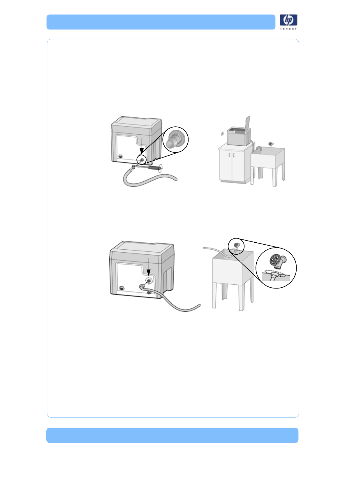
Connect the drain hose
Make sure the drain hose is attached by pushing the end of the drain hose
onto the barbed connection on the back panel of the system. Secure the
hose with the hose clamp using a flat bladed screwdriver. Route the free end
of the drain hose to the wastewater location. Make sure the system is at least
20 cm (8 in.) above the drain hose discharge and there are no kinks in the
hose. The system relies on gravity to drain the wastewater from the cleaning
tank.
Figure 2: Drain hose connections
Connect the water hose
Screw on the end of the water supply hose to the back panel of the system.
Securely tighten the fitting clockwise. Turn on the water and make sure there
are no leaks.
Figure 3: Water hose connections
Plug in the system
Securely plug one end of the supplied power cord into the receptacle at the
back of the system and the other end of the power cord into a grounded
receptacle. Only use the power cord provided.
11
Operation
Cleaning Models
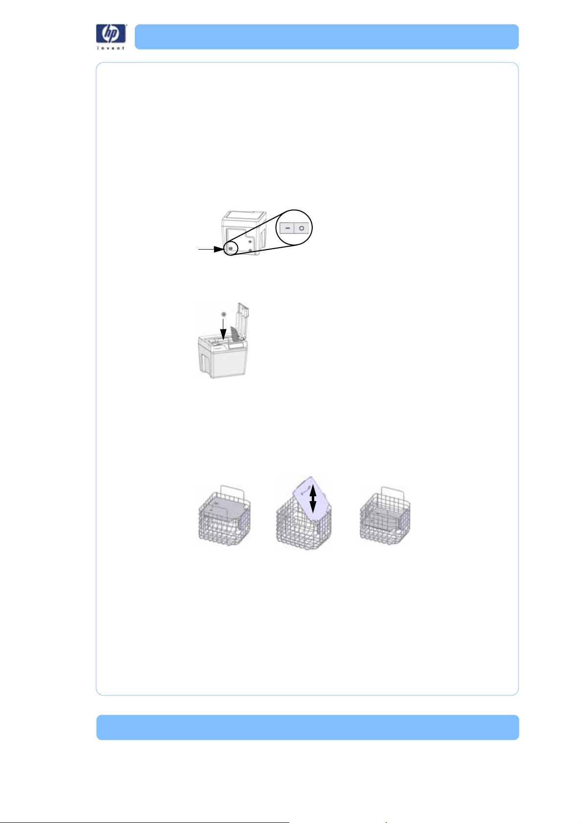
Power on the system
Power on the system using the On/Off switch above the power cord recepta-
cle on the back of the system.
Add models
All models must be placed in the model basket and the model lid adjusted.
The model basket lid ensures the models remain submerged during the
cleaning process. The lid can be adjusted to two heights.
• Use the upper lid position for larger models > 8.89 cm (3.5 in.).
• Use the lower lid position for smaller size models ≤ 8.89 cm (3.5 in.).
• Many models may be cleaned at one time as long as they are sub-
merged during the cleaning process with the model basket lid in either
position.
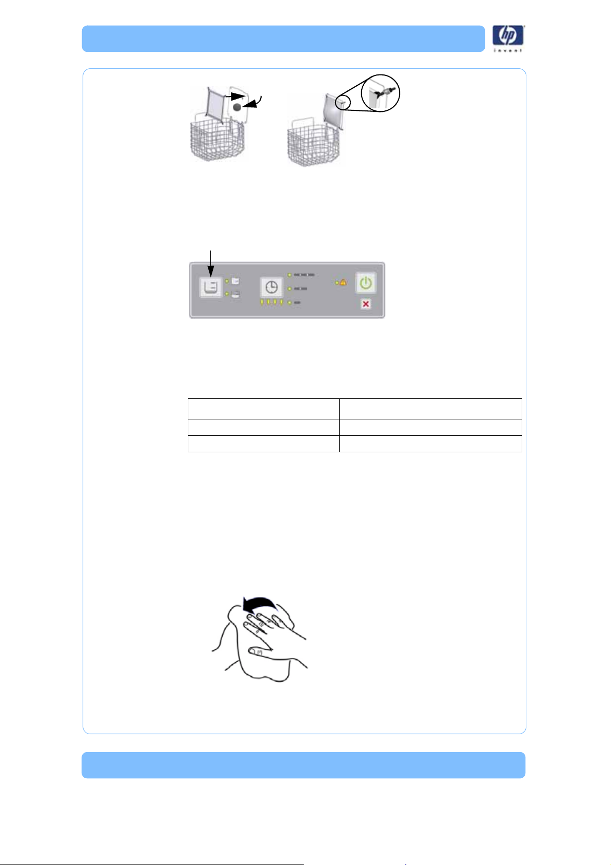
Delicate and flat models should be placed in the model bag on the model
basket lid. When using the model bag, always select the lower lid position
and do not add other models to the model basket.
• Delicate models have features with a cross sectional areas under 19
sq. mm (0.03 sq. in.).
• Flat models have large flat areas that are greater than 64 mm x 64
mm (2.5 in x 2.5 in) and less than 3 mm (1/8 in) thick).
Upper Lid Position
Lower Lid Position
12
Cleaning tank level
Based on the model lid position, select either a full (upper lid position) or
half (lower lid position) cleaning tank level by pressing the cleaning tank
level button. A full cleaning tank level is approximately 15.14 L (4 gals.) and
a half cleaning tank level is approximately 7.57 L (2 gals).
Cleaning agent bag(s)
Select the number of cleaning agent bag(s) to be used based on Table 1
below.
Table 1: Cleaning Tank Level and Cleaning Agent Bags
Note:
Do not use more than the specified amount of cleaning agent
bags. Doing so will exceed pH levels for wastewater dis-
posal.
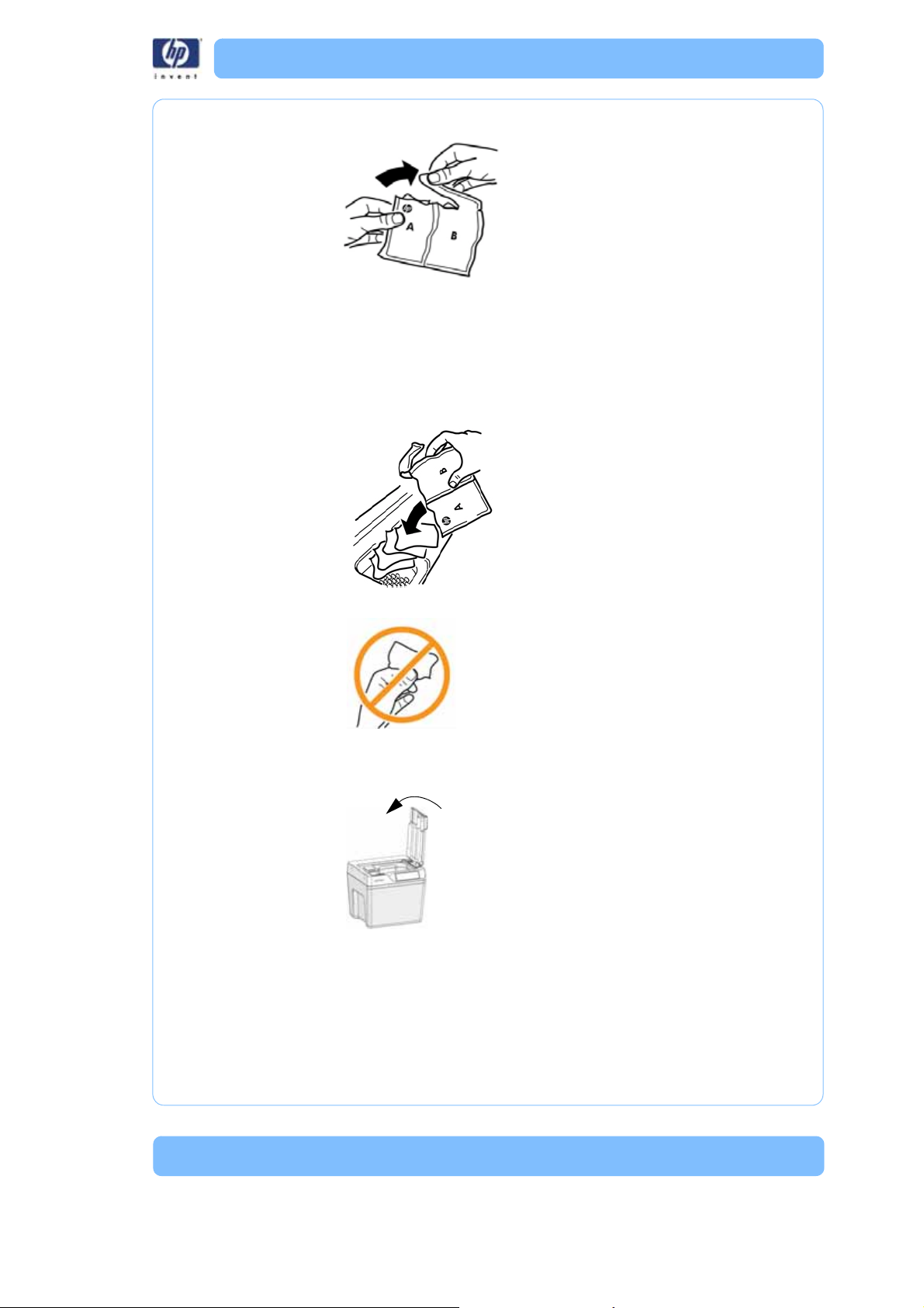
Add cleaning agent bag
Follow the instructions below for adding the contents of the cleaning agent
bag(s) to the cleaning agent receptacle.
1. Dry hands before opening the cleaning agent bag.
Cleaning Tank Level Cleaning Agent Bag
Half cleaning tank level 1 cleaning agent bag
Full cleaning tank level 2 cleaning agent bags
13
2. Open the cleaning agent bag as shown.
3. Empty all the contents of the specified number of cleaning agent
bag into the cleaning agent receptacle as directed (see
<Reference>Table 1).
Note:
Do not use more than the specified amount of cleaning agent
bags. Doing so will exceed pH levels for wastewater dis-
posal.
4. Avoid handling the contents of the cleaning agent bag.
After adding all the contents of the cleaning agent bag(s), properly dispose
of bag(s) and close the system lid.
14
Cycle Length
Select one of the three cycle lengths by pressing the cycle length button.
Each press of the cycle length button increases from a short cycle to a
medium cycle or to a long cycle length. Pressing the cycle length button once
more returns to the short cycle length.
Table 2 should also be used as a general guideline for selecting cycle
lengths for most models.There are some factors that cause the support
removal process to take longer such as model geometry, small support filled
crevices, small blind holes, or low water temperature coming into the system.
Table 2: Cycle Length Settings
Note:
When placing more than one model in the same cleaning
cycle, use the combined build times of all the models to deter-
mine the correct cycle length setting. Combined build time
means the sum of the individual build times of each model
put into the model basket.
Start cycle
When the proper cleaning tank level and cycle length are set, press the start
cycle button. The system locks the lid and begins the process of filling the
cleaning tank, heating the solution, and starts the cleaning of models inside
the cleaning tank.
After the initial cleaning of the models, the system drains and then refills with
clean water for a final rinse and drain cycle. When the cleaning cycle com-
pletes, the left-hand progress LED will turn from yellow to green and the lid
unlocks.
Combined Build Times Cycle Selection Approximate Cycle Times
≤ 4 hrs. Short 3 hrs.
4 to 12 hrs. Medium 6 hrs.
> 12 hrs. Long 12 hrs.
15
Remove the models
Let the solution drain off of the models for a few minutes then remove the
models, wash off any remaining solution and dry with a clean cloth or paper
towel.
Other informati on
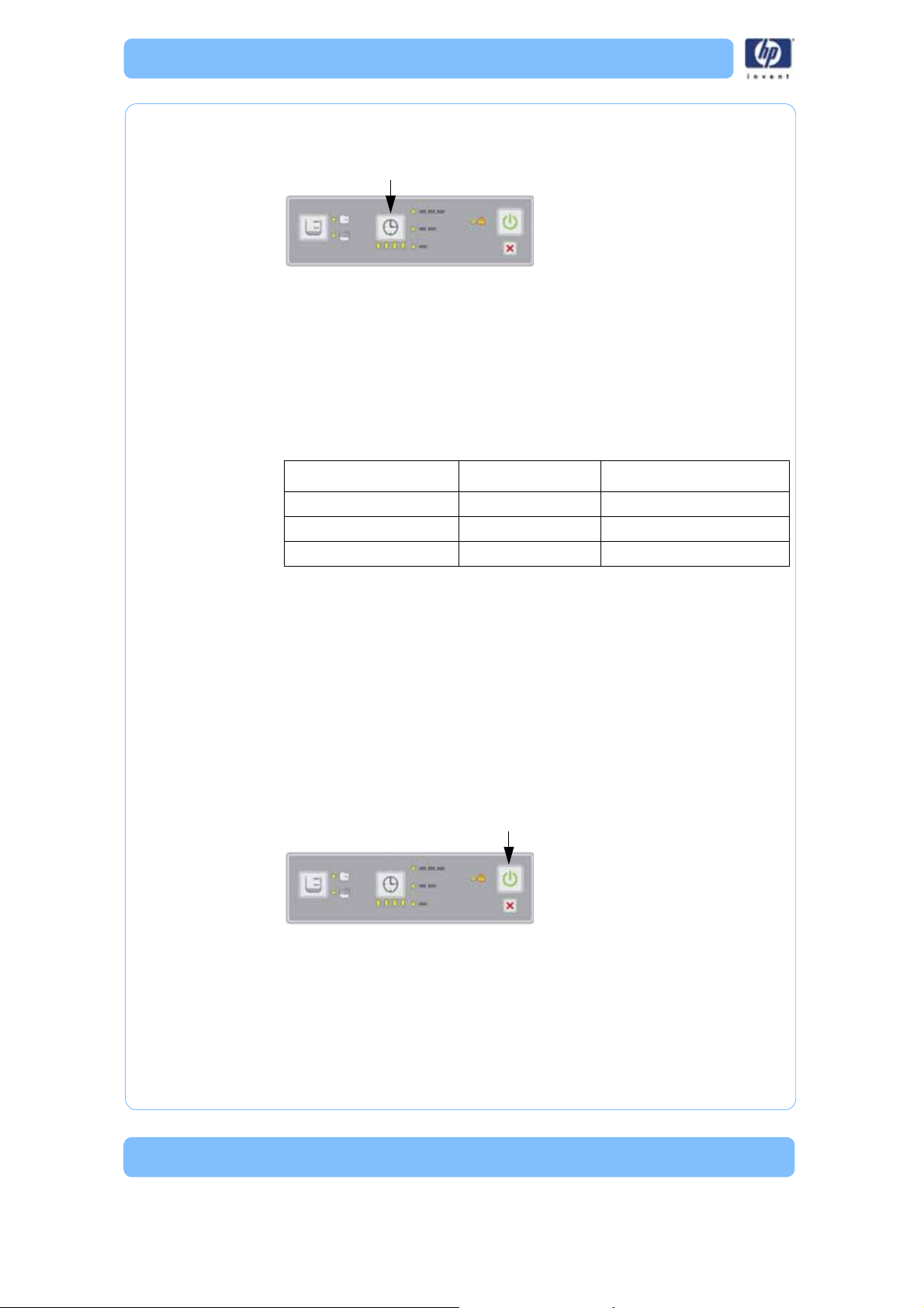
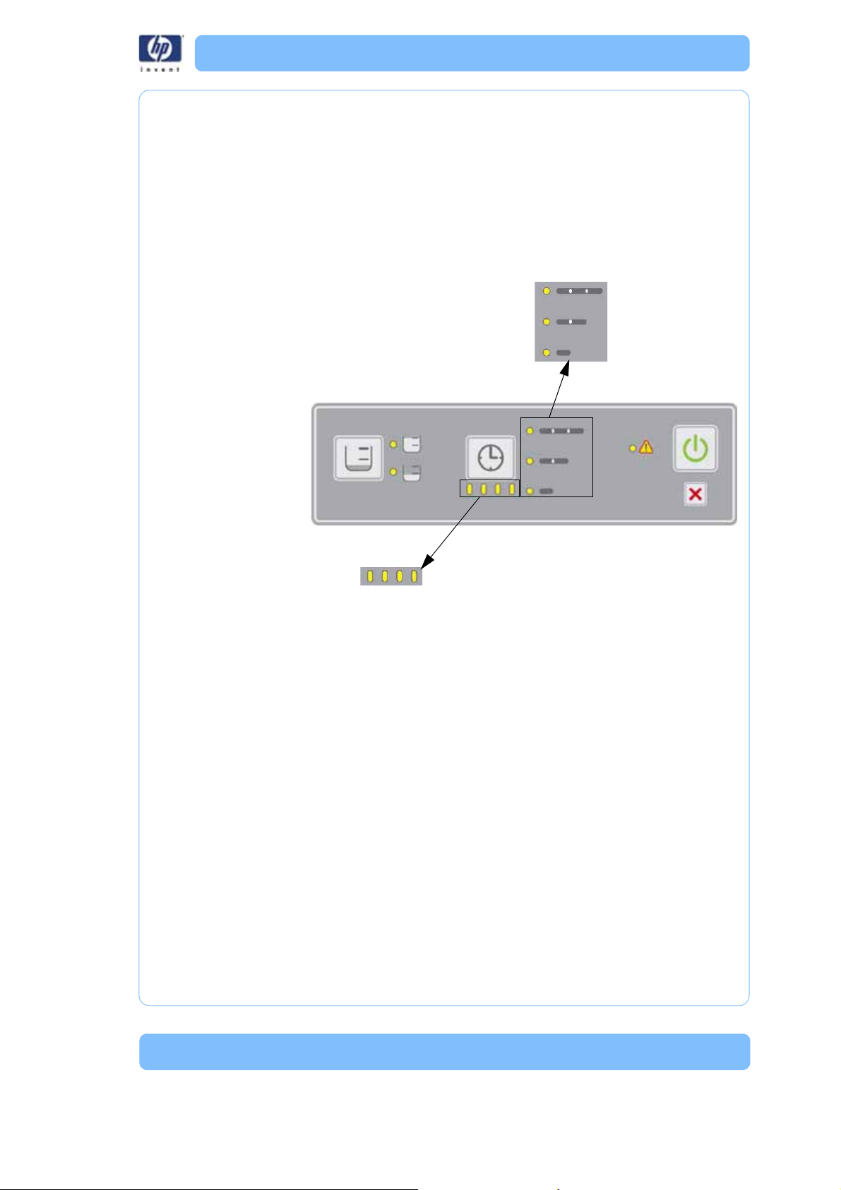
Progress LEDs
When the cleaning cycle is started, all the progress LEDs are illuminated in
yellow. Each progress LED from right to left will turn off as the cycle time pro-
gresses. When the cleaning cycle is complete, the left-hand progress LED will
turn from yellow to green.
Canceling the cleaning cycle
To cancel the cleaning cycle at anytime, press the cancel button on the con-
trol panel. The system will stop and drain the cleaning tank. Before the sys-
tem completely turns off, the cleaning tank may refill with water for a final
rinse (depending on where the system is in the cleaning cycle) and then
drains again. After the cleaning tank has drained, the lid unlocks so the
model basket can be removed. The drained solution cannot be reused. Mod-
els may not be fully cleaned if you cancel the operation.
Cycle
complete

16
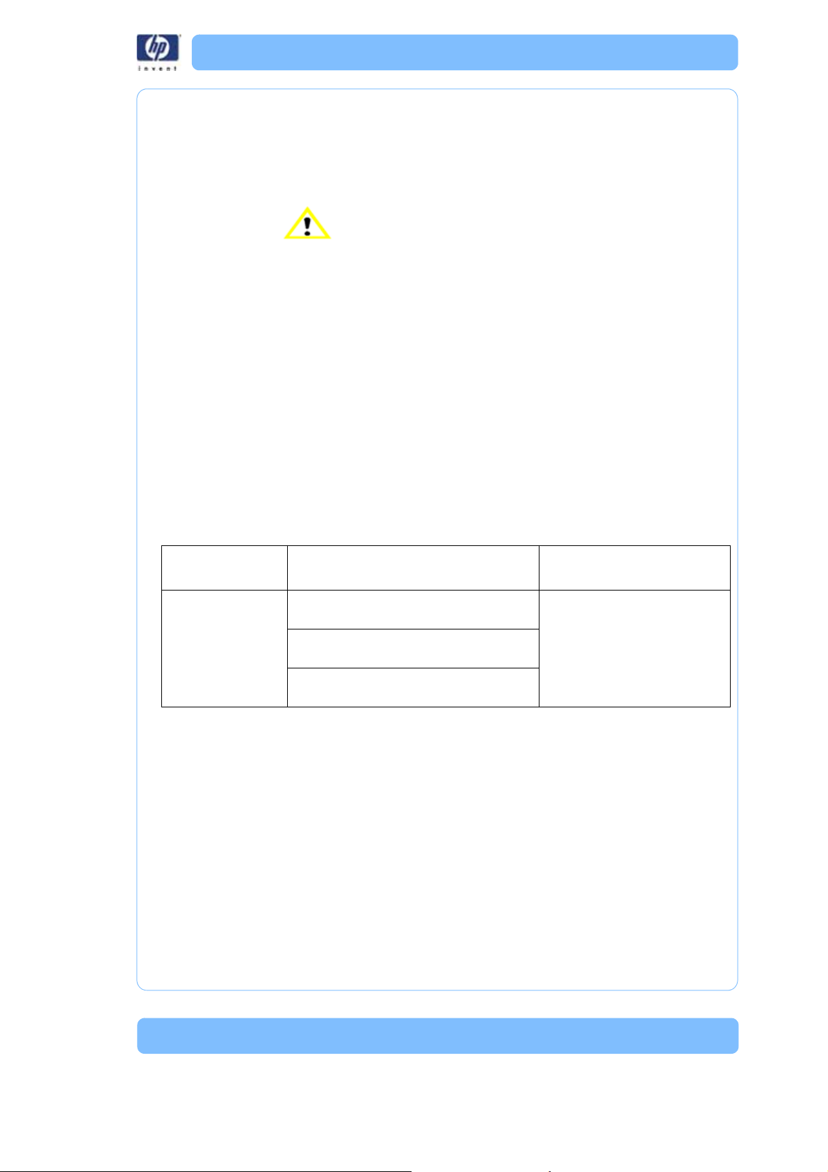
Process error LED
A flashing yellow process error LED indicates a warning. See “Troubleshoot-
ing” on page 19 for details.
A red process error LED indicates that the system is experiencing a system
error. See “Troubleshooting” on page 19 for details.
Turning the system off
Once the cleaning cycle is complete and the models have been removed,
the system should be turned off by toggling the power switch on the back
panel to the OFF position. If the system is not going to be used for an
extended period of time, remove all models from the model basket, make
sure the system is completely dry, and the power cord is disconnected from
the power cord receptacle.

17
Maintenance
Inspecting and cleaning the strainer
The strainer at the bottom of the cleaning tank should be cleaned before
every use of the system to maintain optimal system performance. Remove the
strainer from the cleaning tank and rinse under water until the strainer is
clean. Place the strainer back in the cleaning tank after cleaning.
Cleaning
The system should be cleaned once a month or sooner as needed. Clean the
exterior and the interior of the cleaning tank with mild soap and water using
a sponge or cloth only. Hard to remove residue can be cleaned with isopro-
pyl alcohol. Never immerse the system or use a spray nozzle or hose to
clean it. Any liquid in the electronics area behind the back panel of the sys-
tem may damage the system and void the warranty.
Model bag
The model bag should be replaced after 40 cycles. Replace the bag if the
elastic cord starts to droop or the bag shows signs of wear.

18
19
Troubleshooting
In the presence of unusual electromagnet phenomena, such as strong electro-
magnetic fields or severe electrical disturbances, the system might behave
strangely, or even stop working. In this case, turn off the system, wait until the
electromagnetic environment has returned to normal and then turn it on
again.
The HP Designjet 3D Removal System has been designed to allow the end
user to resolve most operating problems. When a problem is encountered,
read through this troubleshooting section for possible solutions.
Troubleshooting
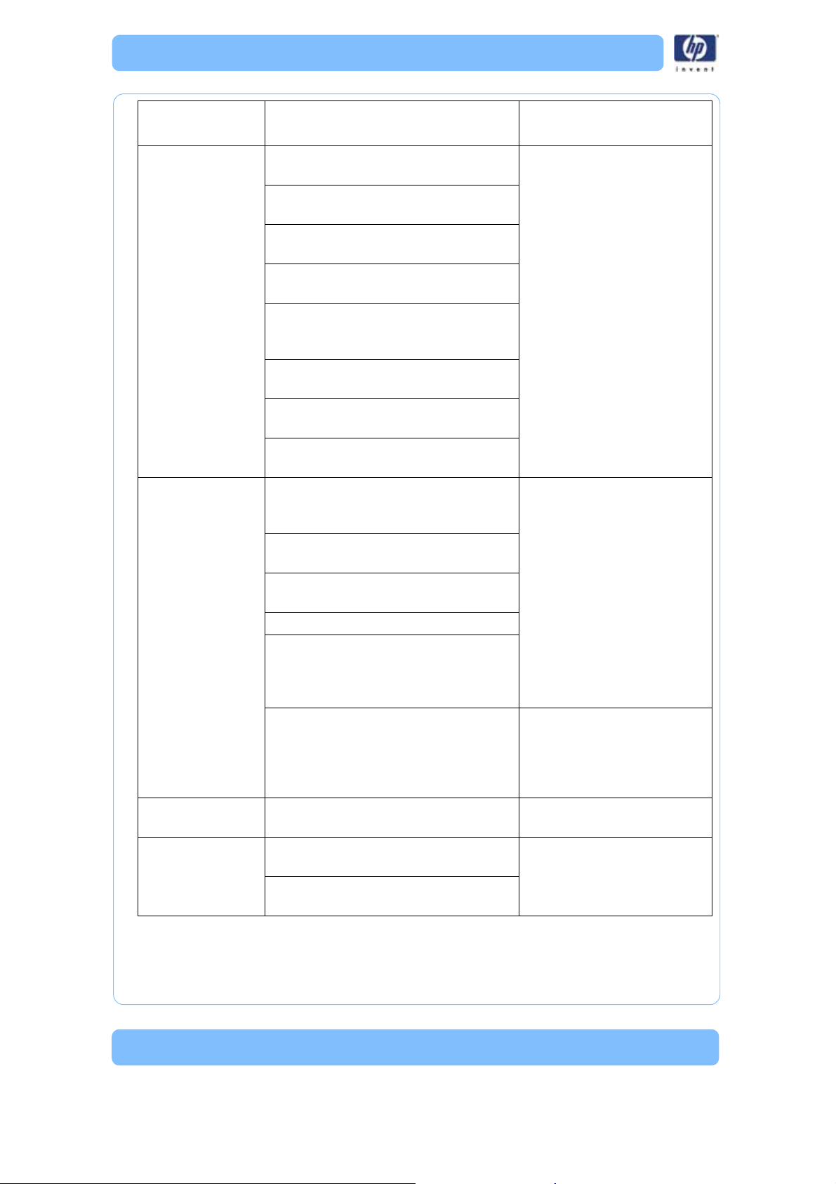
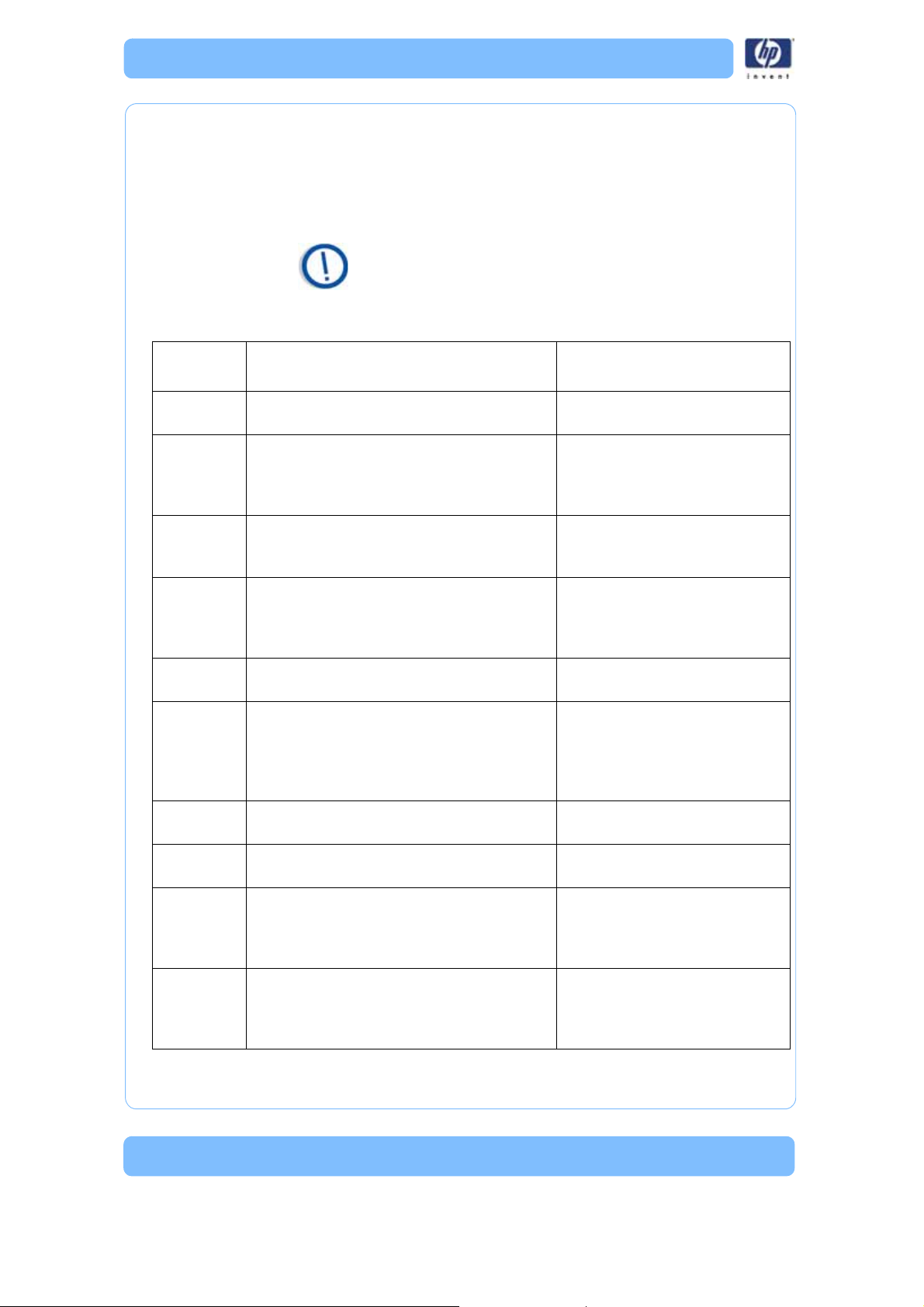
Non-Coded Error Conditions
Table 3: Non-Coded Error Conditions
Problem Recommendation
Replacement Parts
* Part most likely to resolve issue
** Part less likely to resolve issue
No power Verify that the power cord is securely
plugged in.
* Main controller board
** Line filter
** Thermostat
Verify that the power switch is in the
ON position.
Verify that AC power is present at the
power outlet.
20
Water has not
fully drained from
the cleaning tank
assembly
Verify that the strainer and cleaning
tank drain are not clogged.
Verify that the drain hose is not
clogged.
Verify that there are no kinks in the
drain hoses.
Make sure the system is at least 20 cm
(8 in.) above the drain hose discharge.
Make sure that no section of the drain
hose is higher than the system
discharge.
Verify that the power cord is securely
plugged in.
Verify that the power switch is in the
ON position.
Verify that AC power is present at the
power outlet.
Models not clean Make sure all the contents of the speci-
fied number of cleaning agent bag(s) is
used.
* Agitation drive belt
** Induction motor
** Agitation assembly
** Cleaning tank assembly
Make sure the correct cleaning tank
assembly level is selected.
Make sure the correct cycle length is
selected.
Repeat the cleaning cycle.
Make sure the model basket is used to
submerge models in the cleaning solu-
tion and the correct system lid position
is selected.
Cleaning tank assembly not heating. Note: Verify that the tank has
failed to heat before
replacing the cleaning tank
assembly, by touching the
tank during unit operation.
The system is
leaking
Verify that the inlet and drain hose
connections are tight.
Yellow flashing
process error LED
Open and close the system lid and then
make sure the lid is fully closed.
*System lid
** System lid sensor
** Cleaning tank assembly
If recovering from a power loss, press
the cancel button.
Problem Recommendation
Replacement Parts
* Part most likely to resolve issue
** Part less likely to resolve issue
21
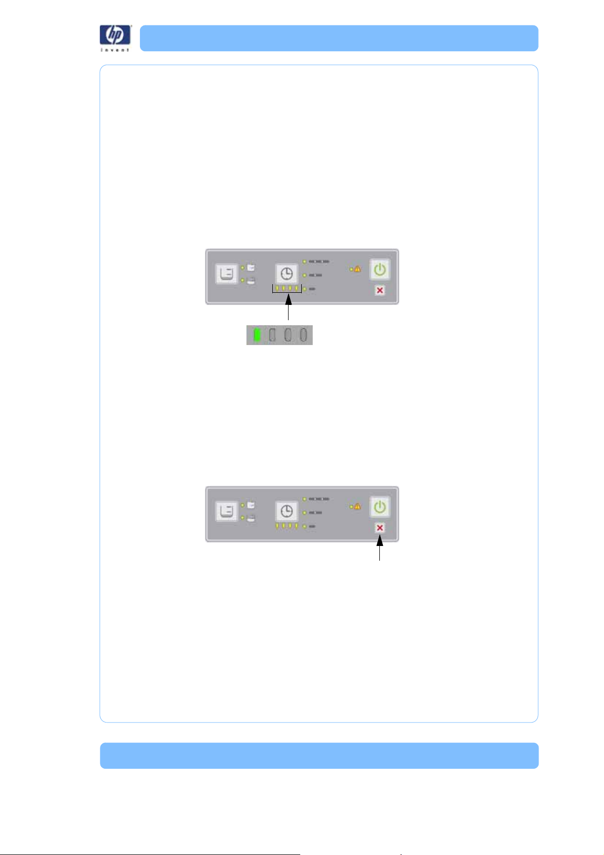
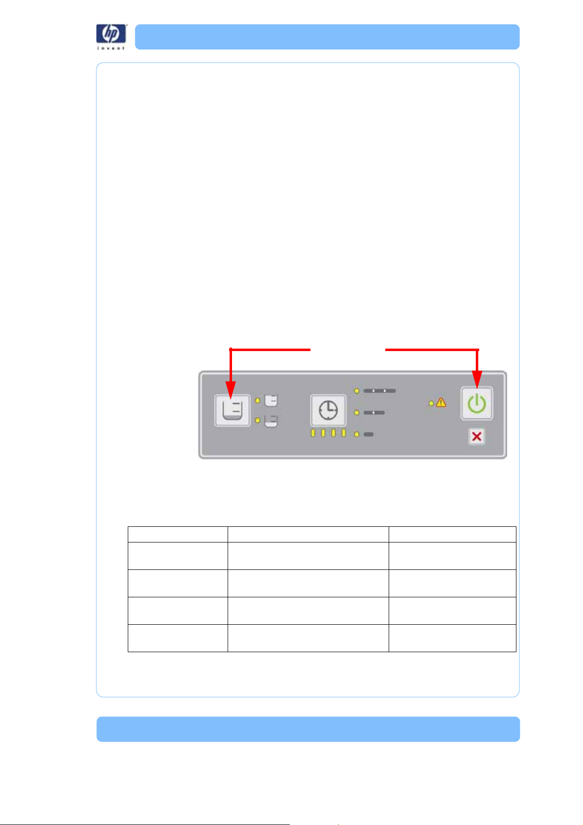
Error Detection
Error Type
Each error type LED carries a weight value (4, 2, or 1). To obtain the error
type number, add up the weight value associated with the illuminated LED.
For example; if the top LED (4) and the bottom LED (1) are both illuminated,
the value equals 5 (4+1=5).
Figure 4: Error Type
Error Type
4
2
1
Value
Error Code
Value
8
4
2
1
22
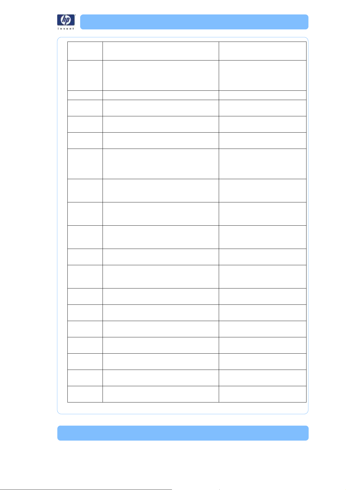
Error Code
Each error code LED carries a weight value (8, 4, 2, or 1). To obtain the
error code number, add up the weight value associated with the illuminated
LED. For example; if the right LED (1) and the third from the right LED (4) are
both illuminated, the value equals 5 (1+4=5).
Table 4: Error Code Chart
Note: To obtain error codes, see “Entering Diagnostic
Mode” on page 25 for details.
Error
Type -Code Description
Replacement Parts
* Part most likely to resolve issue
** Part less likely to resolve issue
1-1 Failed or open thermometer * Thermometer board
** Main controller board
1-8 Set point temperature not reached * Cleaning Tank Assembly
* Main controller board
** Thermometer board
** User interface board
2-1 Ambient temperature error * Thermometer board
** User interface board
** Main controller board
2-2 Wait for high temperature failed * Cleaning Tank Assembly
* Main controller board
** Thermometer board
** User interface board
2-3 Wait for low temperature failed * Thermometer board
** Main controller board
2-4 Wait for the system lid to close failed
1. Check to see if the system lid is closed
2. Check to see if magnet is present in
system lid
CRU:
*System lid
FRU:
* Lid switch assembly
** User interface board
2-5 User interface to main controller
communication error
* User interface board
* Main controller board
2-6 Thermometer communication error * Thermometer board
* User interface board
2-7 Float level sensor assembly not empty
1. Check for drain hose blocked or
mis-routed
2. Check to see if drain screen is clean
* Float level sensor assembly
** Cleaning tank assembly
3-1 System lid open while washing
Check if magnet is secure in system lid
* System lid lock assembly
** System lid switch assembly
** User interface board
** Main controller board
23
3-2 System lid open while rinsing
Check if magnet is secure in system lid
* System lid lock assembly
** System switch assembly
** User interface board
** Main controller board
3-3 Power module fault detected * Main controller board
3-4 User interface to main controller
communication error
* User interface board
* Main control board
3-10 Invalid float level sensor assembly state * Float level sensor assembly
** Main controller board
4-1 Invalid float level sensor assembly state * Float level sensor assembly
** Main controller board
4-2 Timeout waiting for low water level
1. Check for water available at inlet
2. Check water pressure at inlet
* Cleaning tank assembly
** Inlet hose
** Main controller board
** Float level sensor assembly
4-3 Timeout waiting for mid water level
1. Check for water available at inlet
2. Check water pressure at inlet
* Cleaning tank assembly
** Float level sensor assembly
** Main controller board
4-4 Unexpected transition to overfill condition * Float level sensor assembly
** Cleaning tank assembly
** Main controller board
4-5 Timeout waiting for full water level
1. Check for water available at inlet
2. Check water pressure at inlet
* Float level sensor assembly
* Cleaning tank assembly
** Main controller board
4-6 Float level sensor assembly error - empty
switch stuck closed
* Float level sensor assembly
** Main controller board
4-7 Timeout waiting for full water level
1. Check for water available at inlet
2. Check water pressure at inlet
* Float level sensor assembly
* Cleaning tank assembly
** Main controller board
4-8 Overfill: Float level sensor assembly error -
mid switch stuck open
* Float level sensor assembly
** Main controller board
4-9 Float level sensor assembly error - mid
switch stuck open
* Float level sensor assembly
** Main controller board
4-10 Float level sensor assembly error - empty
switch stuck closed
* Float level sensor assembly
** Main controller board
4-11 Not empty at start of fill * Float level sensor assembly
** Main controller board
4-12 Float level sensor assembly error (full before
mid)
* Float level sensor assembly
** Main controller board
4-13 Not at target level at the end of fill * Float level sensor assembly
** Main controller board
5-1 Invalid float level sensor assembly state * Float level sensor assembly
** Main controller board
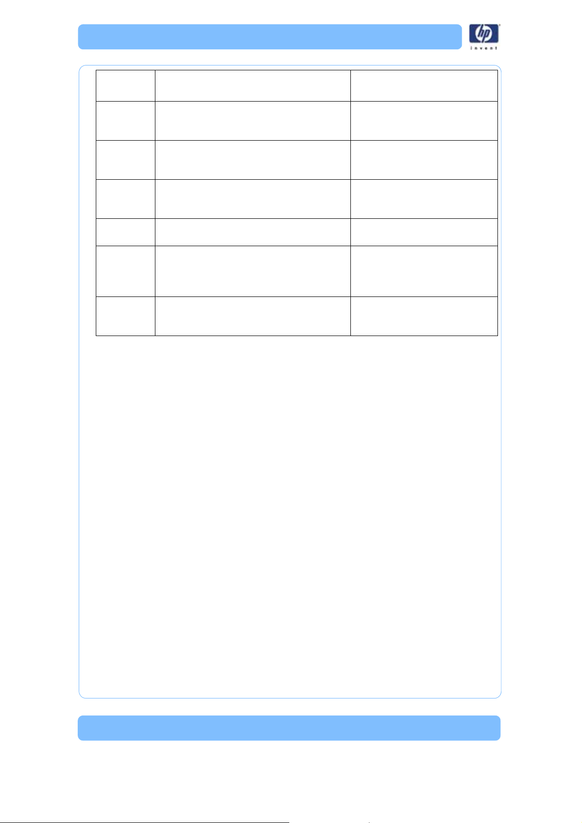
Error
Type -Code Description
Replacement Parts
* Part most likely to resolve issue
** Part less likely to resolve issue
24
5-2 Unexpected loss of fluid * Cleaning tank assembly
** Float level board
** Main controller board
5-3 Overfill * Cleaning tank assembly
** Float level board
** Main controller board
5-4 Unexpected loss of fluid and invalid sensor
transition
* Float level sensor assembly
** Main controller board
** Cleaning tank assembly
6-1 Invalid float level sensor assembly state * Float level sensor assembly
** Main controller board
6-2 Timeout waiting for empty
1. Check for drain hose blocked or
mis-routed
2. Check drain screen clean
* Float level sensor assembly
* Cleaning tank assembly
6-3 Unexpected addition of fluid * Cleaning tank assembly
** Float level sensor assembly
** Main controller board
Error
Type -Code Description
Replacement Parts
* Part most likely to resolve issue
** Part less likely to resolve issue
25
Diagnostic and Test Specifications
Functional Description
Overview
The diagnostic test feature is intended to allow the support engineer to con-
firm correct operation of a majority of the system’s hardware. Diagnostic test-
ing does not require water be connected to the cleaning tank assembly for
the test sequence to complete successfully. The support engineer will be
required to verify certain hardware is operating properly where the cleaning
tank assembly itself is not capable of detecting it automatically.
Entering Diagnostic Mode
Diagnostic mode can only be entered when the system is initially powered
off. To enter diagnostic mode, the support engineer must simultaneously hold
down only the ‘start’ and ‘load select’ buttons (farthest apart) when power is
turned on. The system is now in diagnostic mode (indicated by both 'cycle
load' LEDs being ON simultaneously and all ‘cycle length’ and ‘progress sta-
tus’ LEDs OFF, neither of which should ever occur during normal operating
mode). Normal operation cannot be resumed until this mode is exited. Note
that the input buttons have different functions when in diagnostic mode.
Input functions in Diagnostic Mode
The affect of pressing the interface panel buttons changes when diagnostic
mode is active.
Press Together
Button Normal mode (for reference only) Diagnostic model
Cycle ‘Load Select’ Rotate though water level options
(FullHalfFull...)
Select subtest (sequential
Cycle ‘Length Select’ Rotate though cycle length options
(Long Med Short Long...)
Run selected subtest
‘Start’ Begin selected cleaning operation Run all diagnostic subtests
(run remaining subtests)
‘Cancel’ Abort any operation in progress Exit diagnostic mode(abort
current subtest)
Loading...