


 Loading...
Hardware Reference Guide
HP Compaq 6000 Pro Microtower Business PC
© Copyright 2009 Hewlett-Packard Development Company, L.P. The information contained herein is subject to change without notice.
Microsoft, Windows, and Windows Vista are either trademarks or registered trademarks of Microsoft Corporation in the United States and/or other countries.
The only warranties for HP products and services are set forth in the express warranty statements accompanying such products and services. Nothing herein should be construed as constituting an additional warranty. HP shall not be liable for technical or editorial errors or omissions contained herein.
This document contains proprietary information that is protected by copyright. No part of this document may be photocopied, reproduced, or translated to another language without the prior written consent of Hewlett-Packard Company.
Hardware Reference Guide
HP Compaq 6000 Pro Microtower Business
PC
First Edition (September 2009)
Document Part Number: 576435-001

About This Book
This guide provides basic information for upgrading this computer model.
 WARNING! Text set off in this manner indicates that failure to follow directions could result in bodily harm or loss of life.
 CAUTION: Text set off in this manner indicates that failure to follow directions could result in damage to equipment or loss of information.
 NOTE: Text set off in this manner provides important supplemental information.
ENWW |
iii |
iv About This Book |
ENWW |

Table of contents
1 Product Features |
|
Standard Configuration Features ......................................................................................................... |
1 |
Front Panel Components ..................................................................................................................... |
2 |
Media Card Reader Components ......................................................................................................... |
3 |
Rear Panel Components ...................................................................................................................... |
4 |
Keyboard .............................................................................................................................................. |
5 |
Using the Windows Logo Key .............................................................................................. |
6 |
Serial Number Location ........................................................................................................................ |
7 |
2 Hardware Upgrades |
|
Serviceability Features ......................................................................................................................... |
8 |
Warnings and Cautions ........................................................................................................................ |
8 |
Removing the Computer Access Panel ................................................................................................ |
9 |
Replacing the Computer Access Panel .............................................................................................. |
10 |
Removing the Front Bezel .................................................................................................................. |
11 |
Removing Bezel Blanks ..................................................................................................................... |
12 |
Replacing the Front Bezel .................................................................................................................. |
12 |
Installing Additional Memory .............................................................................................................. |
13 |
DIMMs ............................................................................................................................... |
13 |
DDR3-SDRAM DIMMs ...................................................................................................... |
13 |
Populating DIMM Sockets ................................................................................................. |
14 |
Installing DIMMs ................................................................................................................ |
15 |
Removing or Installing an Expansion Card ........................................................................................ |
17 |
Drive Positions ................................................................................................................................... |
21 |
Installing and Removing Drives .......................................................................................................... |
22 |
System Board Drive Connections ...................................................................................... |
24 |
Removing an External 5.25-inch or 3.5-inch Drive ............................................................ |
25 |
Installing an External 5.25-inch or 3.5-inch Drive .............................................................. |
28 |
Removing an Internal 3.5-inch Hard Drive ......................................................................... |
32 |
Installing an Internal 3.5-inch Hard Drive ........................................................................... |
34 |
Removing and Replacing a Removable 3.5-inch SATA Hard Drive .................................. |
36 |
Appendix A Specifications |
|
ENWW |
v |
Appendix B Battery Replacement |
|
Appendix C External Security Devices |
|
Installing a Security Lock .................................................................................................................... |
46 |
Cable Lock ......................................................................................................................... |
46 |
Padlock .............................................................................................................................. |
47 |
HP Business PC Security Lock .......................................................................................... |
47 |
Front Bezel Security .......................................................................................................... |
49 |
Appendix D Electrostatic Discharge |
|
Preventing Electrostatic Damage ....................................................................................................... |
51 |
Grounding Methods ............................................................................................................................ |
51 |
Appendix E Computer Operating Guidelines, Routine Care and Shipping Preparation |
|
Computer Operating Guidelines and Routine Care ............................................................................ |
52 |
Optical Drive Precautions ................................................................................................................... |
53 |
Operation ........................................................................................................................... |
53 |
Cleaning ............................................................................................................................. |
53 |
Safety ................................................................................................................................. |
53 |
Shipping Preparation .......................................................................................................................... |
53 |
Index ................................................................................................................................................................... |
54 |
vi |
ENWW |
1 Product Features
Standard Configuration Features
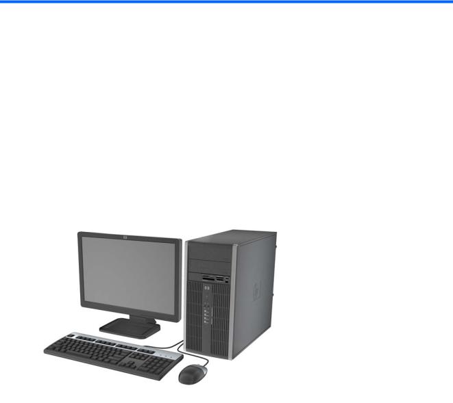
The HP Compaq Microtower features may vary depending on the model. For a complete listing of the hardware and software installed in the computer, run the diagnostic utility (included on some computer models only). Instructions for using the utility are provided in the Troubleshooting Guide.
Figure 1-1 Microtower Configuration
ENWW |
Standard Configuration Features 1 |
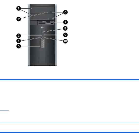
Front Panel Components
Drive configuration may vary by model.
Table 1-1 Front Panel Components
1 |
5.25-inch Optical Drives1 |
6 |
Optical Drive Eject Buttons |
2 |
Optical Drive Activity Lights |
7 |
3.5-inch Media Card Reader (optional)2 |
3 |
Hard Drive Activity Light |
8 |
Dual-State Power Button |
|
|
|
|
4 |
Microphone/Headphone Connector |
9 |
Power On Light |
|
|
|
|
5 |
USB (Universal Serial Bus) 2.0 Ports |
10 |
Headphone Connector |
NOTE: When a device is plugged into the Microphone/Headphone Connector, a dialog box will pop up asking if you want to use the connector for a microphone line Line-In device or a headphone. You can reconfigure the connector at any time by double-clicking the Realtek HD Audio Manager icon in the Windows taskbar.
NOTE: The Power On Light is normally green when the power is on. If it is flashing red, there is a problem with the computer and it is displaying a diagnostic code. Refer to the Troubleshooting Guide to interpret the code.
1Some models have bezel blanks covering one or both of the 5.25-inch drive bays.
2Some models have a bezel blank covering the 3.5-inch drive bay.
2 Chapter 1 Product Features |
ENWW |
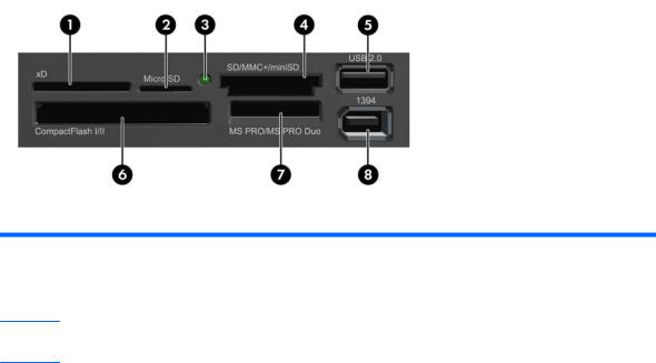
Media Card Reader Components
The media card reader is an optional device available on some models only. Refer to the following illustration and table to identify the media card reader components.
Figure 1-2 Media Card Reader Components
Table 1-2 Media Card Reader Components
No. |
Slot |
Media |
|
|
|
|
|
|
|
1 |
xD |
● |
xD-Picture Card (xD) |
|
|
|
|
|
|
2 |
MicroSD |
● |
MicroSD (T-Flash) |
● MicroSDHC |
3Media Card Reader Activity Light
4 |
SD/MMC+/miniSD |
● |
Secure Digital (SD) |
● |
MiniSDHC |
● |
MultiMediaCard 4.0 |
|
|
● |
Secure Digital High |
● |
MultiMediaCard |
|
(MMC Plus) |
|
|
|
|
||||
|
|
|
Capacity (SDHC) |
|
(MMC) |
● |
Reduced Size |
|
|
● |
MiniSD |
● |
Reduced Size |
|
MultiMediaCard 4.0 |
|
|
|
(MMC Mobile) |
||||
|
|
|
|
|
MultiMediaCard (RS |
|
|
|
|
|
|
|
MMC) |
● |
MMC Micro (adapter |
|
|
|
|
|
|
|
required) |
|
|
|
|
|
|
|
|
5 |
USB |
● |
USB (Universal Serial |
|
|
|
|
|
|
|
Bus) Port |
|
|
|
|
|
|
|
|
|
|
|
|
6 |
CompactFlash I/II |
● |
CompactFlash Card |
● |
CompactFlash Card |
● |
MicroDrive |
|
|
|
Type 1 |
|
Type 2 |
|
|
|
|
|
|
|
|
|
|
7 |
MS PRO/MS PRO DUO |
● |
Memory Stick (MS) |
● |
Memory Stick Select |
● |
Memory Stick PRO |
|
|
● |
MagicGate Memory |
● |
Memory Stick Duo |
|
Duo (MS PRO Duo) |
|
|
|
|
||||
|
|
|
Stick (MG) |
|
(MS Duo) |
● |
Memory Stick PRO- |
|
|
● |
MagicGate Memory |
● |
Memory Stick PRO |
|
HG Duo |
|
|
|
|
||||
|
|
|
Duo |
|
(MS PRO) |
● |
Memory Stick Micro |
|
|
|
|
|
|
|
(M2) (adapter |
|
|
|
|
|
|
|
required) |
|
|
|
|
|
|
|
|
8 |
1394 |
● |
1394 Port (available |
|
|
|
|
|
|
|
on select models only) |
|
|
|
|
|
|
|
|
|
|
|
|
ENWW |
Media Card Reader Components 3 |
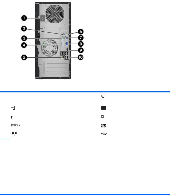
Rear Panel Components
Table 1-3 Rear Panel Components
1 |
Power Cord Connector |
6 |
Line-Out Connector for powered audio |
|
|
|
devices (green) |
|
|
|
|
2 |
Line-In Audio Connector (blue) |
7 |
PS/2 Keyboard Connector (purple) |
|
|
|
|
3 |
PS/2 Mouse Connector (green) |
8 |
VGA Monitor Connector |
|
|
|
|
4 |
Serial Connector |
9 |
DisplayPort Monitor Connector |
|
|
|
|
5 |
RJ-45 Network Connector |
10 |
Universal Serial Bus (USB) |
NOTE: Arrangement and number of connectors may vary by model.
An optional second serial port and an optional parallel port are available from HP.
When a device is plugged into the blue Line-In Audio Connector, a dialog box will pop up asking if you want to use the connector for a line-in device or a microphone. You can reconfigure the connector at any time by double-clicking the Realtek HD Audio Manager icon in the Windows taskbar.
The monitor connectors on the system board are inactive when a graphics card is installed in the computer.
If a graphics card is installed into the PCI or PCI Express x1 slot, the connectors on the graphics card and the system board may be used at the same time. Some settings may need to be changed in Computer Setup to use both connectors. For information about setting the boot VGA controller, refer to the Computer Setup (F10) Utility Guide.
4 Chapter 1 Product Features |
ENWW |
Keyboard
Table 1-4 Keyboard Components
1 |
Function Keys |
Perform special functions depending on the software application being used. |
|
|
|
|
|
2 |
Editing Keys |
Includes the following: Insert, Home, Page Up, Delete, End, and Page Down. |
|
|
|
|
|
3 |
Status Lights |
Indicate the status of the computer and keyboard settings (Num Lock, Caps Lock, |
|
|
|
|
and Scroll Lock). |
|
|
|
|
4 |
Numeric Keys |
Work like a calculator keypad. |
|
|
|
|
|
5 |
Arrow Keys |
Used to navigate through a document or Web site. These keys allow you to move |
|
|
|
|
left, right, up, and down, using the keyboard instead of the mouse. |
|
|
|
|
6 |
Ctrl Keys |
Used in combination with another key; their effect depends on the application |
|
|
|
|
software you are using. |
|
|
|
|
7 |
Application Key1 |
Used (like the right mouse button) to open pop-up menus in a Microsoft Office |
|
|
|
|
application. May perform other functions in other software applications. |
|
|
|
|
8 |
Windows Logo Keys1 |
Used to open the Start menu in Microsoft Windows. Used in combination with other |
|
|
|
|
keys to perform other functions. |
|
|
|
|
9 |
Alt Keys |
Used in combination with another key; their effect depends on the application |
|
|
|
|
software you are using. |
|
|
||
|
1 |
Keys available in select geographic regions. |
|
ENWW |
Keyboard 5 |

Using the Windows Logo Key
Use the Windows Logo key in combination with other keys to perform certain functions available in the Windows operating system. Refer to the Keyboard on page 5 section to identify the Windows Logo key.
Table 1-5 Windows Logo Key Functions
The following Windows Logo Key functions are available in Microsoft Windows XP and Microsoft Windows Vista.
Windows Logo Key |
Displays or hides the Start menu |
|
|
Windows Logo Key + d |
Displays the Desktop |
|
|
Windows Logo Key + m |
Minimizes all open applications |
|
|
Shift + Windows Logo Key + m |
Undoes Minimize All |
|
|
Windows Logo Key + e |
Launches My Computer |
|
|
Windows Logo Key + f |
Launches Find Document |
|
|
Windows Logo Key + Ctrl + f |
Launches Find Computer |
|
|
Windows Logo Key + F1 |
Launches Windows Help |
|
|
Windows Logo Key + l |
Locks the computer if you are connected to a network domain, or |
|
allows you to switch users if you are not connected to a network |
|
domain |
|
|
Windows Logo Key + r |
Launches the Run dialog box |
|
|
Windows Logo Key + u |
Launches the Utility Manager |
|
|
Windows Logo Key + Tab |
Cycles through the Taskbar buttons (Windows XP) |
|
Cycles through programs on the Taskbar using the Windows Flip |
|
3-D (Windows Vista) |
In addition to the Windows Logo Key functions described above, the following functions are also available in Microsoft Windows Vista.
Ctrl + Windows Logo Key + Tab
Windows Logo Key + Spacebar |
Bring all gadgets to the front and select Windows Sidebar |
|
|
Windows Logo Key + g |
Cycle through Sidebar gadgets |
|
|
Windows Logo Key + u |
Launches Ease of Access Center |
|
|
Windows Logo Key + any number key |
Launches the Quick Launch shortcut that is in the position that |
|
corresponds to the number (for example, Windows Logo Key + 1 |
|
launches the first shortcut in the Quick Launch menu) |
|
|
6 Chapter 1 Product Features |
ENWW |
Serial Number Location
Each computer has a unique serial number and product ID number that are located on the top cover of the computer. Keep these numbers available for use when contacting customer service for assistance.
Figure 1-3 Serial Number and Product ID Location
ENWW |
Serial Number Location 7 |

2 Hardware Upgrades
Serviceability Features
The computer includes features that make it easy to upgrade and service. No tools are needed for most of the installation procedures described in this chapter.
Warnings and Cautions
Before performing upgrades be sure to carefully read all of the applicable instructions, cautions, and warnings in this guide.
 WARNING! To reduce the risk of personal injury from electrical shock, hot surfaces, or fire:
Disconnect the power cord from the wall outlet and allow the internal system components to cool before touching.
Do not plug telecommunications or telephone connectors into the network interface controller (NIC) receptacles.
Do not disable the power cord grounding plug. The grounding plug is an important safety feature.
Plug the power cord in a grounded (earthed) outlet that is easily accessible at all times.
To reduce the risk of serious injury, read the Safety & Comfort Guide. It describes proper workstation, setup, posture, and health and work habits for computer users, and provides important electrical and mechanical safety information. This guide is located on the Web at http://www.hp.com/ergo.
WARNING! Energized and moving parts inside.
Disconnect power to the equipment before removing the enclosure.
Replace and secure the enclosure before re-energizing the equipment.
 CAUTION: Static electricity can damage the electrical components of the computer or optional equipment. Before beginning these procedures, ensure that you are discharged of static electricity by briefly touching a grounded metal object. See Appendix D, Electrostatic Discharge on page 51 for more information.
When the computer is plugged into an AC power source, voltage is always applied to the system board. You must disconnect the power cord from the power source before opening the computer to prevent damage to internal components.
8 Chapter 2 Hardware Upgrades |
ENWW |
Removing the Computer Access Panel
1.Remove/disengage any security devices that prohibit opening the computer.
2.Remove all removable media, such as compact discs or USB flash drives, from the computer.
3.Turn off the computer properly through the operating system, then turn off any external devices.
4.Disconnect the power cord from the power outlet and disconnect any external devices.
 CAUTION: Regardless of the power-on state, voltage is always present on the system board as long as the system is plugged into an active AC outlet. You must disconnect the power cord to avoid damage to the internal components of the computer.
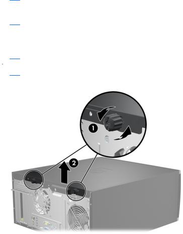
5.Loosen the two captive thumbscrews (1) that secure the access panel to the computer chassis.
6.Use the handle located between the thumbscrews to lift the access panel off the unit (2).
 NOTE: You may want to lay the computer on its side to install internal parts. Be sure the side with the access panel is facing up.
Figure 2-1 Removing the Computer Access Panel
ENWW |
Removing the Computer Access Panel 9 |
Replacing the Computer Access Panel
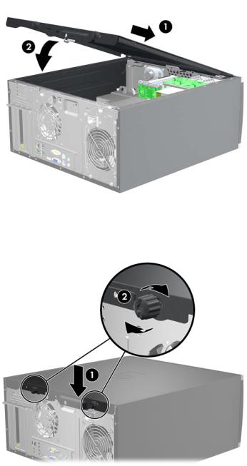
1.Slide the lip on the front end of the access panel under the lip on the front of the chassis (1) then press the back end of the access panel onto the unit (2).
Figure 2-2 Replacing the Computer Access Panel
2.Ensure that the panel is completely closed (1) and tighten the two thumbscrews that secure the access panel to the chassis (2).
Figure 2-3 Tightening the Access Panel Thumbscrews
10 Chapter 2 Hardware Upgrades |
ENWW |
Removing the Front Bezel
1.Remove/disengage any security devices that prohibit opening the computer.
2.Remove all removable media, such as compact discs or USB flash drives, from the computer.
3.Turn off the computer properly through the operating system, then turn off any external devices.
4.Disconnect the power cord from the power outlet and disconnect any external devices.
 CAUTION: Regardless of the power-on state, voltage is always present on the system board as long as the system is plugged into an active AC outlet. You must disconnect the power cord to avoid damage to the internal components of the computer.
5.Remove the computer access panel.
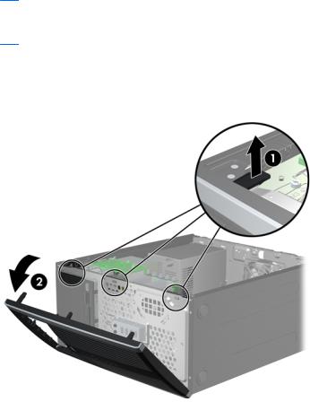
6.Lift up the three tabs on the side of the bezel (1), then rotate the bezel off the chassis (2).
Figure 2-4 Removing the Front Bezel
ENWW |
Removing the Front Bezel 11 |

Removing Bezel Blanks
On some models, there are bezel blanks covering the 3.5-inch and 5.25-inch external drive bays that need to be removed before installing a drive. To remove a bezel blank:
1.Remove the access panel and front bezel.
2.To remove a bezel blank, push the two retaining tabs that hold the bezel blank in place towards the outer right edge of the bezel (1) and slide the bezel blank back and to the right to remove it (2).
Figure 2-5 Removing a Bezel Blank
Replacing the Front Bezel
Insert the three hooks on the left side of the bezel into the rectangular holes on the chassis (1) then rotate the right side of the bezel onto the chassis (2) and snap it into place.
Figure 2-6 Replacing the Front Bezel
12 Chapter 2 Hardware Upgrades |
ENWW |

Installing Additional Memory
The computer comes with double data rate 3 synchronous dynamic random access memory (DDR3SDRAM) dual inline memory modules (DIMMs).
DIMMs
The memory sockets on the system board can be populated with up to four industry-standard DIMMs. These memory sockets are populated with at least one preinstalled DIMM. To achieve the maximum memory support, you can populate the system board with up to 16-GB of memory configured in a highperforming dual channel mode.
DDR3-SDRAM DIMMs
For proper system operation, the DDR3-SDRAM DIMMs must be:
●industry-standard 240-pin
●unbuffered non-ECC PC3-8500 DDR3-1066 MHz-compliant or PC3-10600 DDR3-1333 MHzcompliant
 NOTE: 1333 MHz DIMMS will only run at a speed of 1066 MHz.
●1.5 volt DDR3-SDRAM DIMMs The DDR3-SDRAM DIMMs must also:
●support CAS latency 7 DDR3 1066 MHz (7-7-7 timing) and CAS latency 9 DDR3 1333 MHz (9-9-9 timing)
●contain the mandatory JEDEC SPD information
In addition, the computer supports:
●512-Mbit, 1-Gbit, and 2-Gbit non-ECC memory technologies
●single-sided and double-sided DIMMs
●DIMMs constructed with x8 and x16 DDR devices; DIMMs constructed with x4 SDRAM are not supported
 NOTE: The system will not operate properly if you install unsupported DIMMs.
ENWW |
Installing Additional Memory 13 |
Loading...