


8550, 8550N, 8550DN, 8550GN, 8550MFP Printer
Getting Started Guide
English
HP Color LaserJet 8550, 8550N, 8550DN, 8550GN, 8550MFP Printer
Getting Started Guide
Copyright Information
©2000 Hewlett-Packard
Company
All Rights Reserved. Reproduction, adaptation, or translation without prior written permission is prohibited, except as allowed under the copyright laws.
Part number: C7096-90923 First Edition: April, 2000
Warranty
The information contained in this document is subject to change without notice.
Hewlett-Packard makes no warranty of any kind with respect to this information. HEWLETT-PACKARD SPECIFICALLY DISCLAIMS THE IMPLIED WARRANTY OF MERCHANTABILITY AND FITNESS FOR A PARTICULAR PURPOSE.
Hewlett-Packard shall not be liable for any direct, indirect, incidental, consequential, or other damage alleged in connection with the furnishing or use of this information.
Trademark Credits
AdobeTM is a trademark of Adobe Systems Incorporated which may be registered in certain jurisdictions.
CompuServeTM is a U.S. trademark of CompuServe, Inc.
HP-UX 9.* and 10.0 for HP 9000 Series 700 and 800 computers are X/Open Company UNIX 93 branded products.
Microsoft® , Windows® , Windows NT® , and MS-DOS® are U.S. registered trademarks of Microsoft Corporation.
PostScriptTM is a trademark of Adobe Systems Incorporated which may be registered in certain jurisdictions.
UNIX® is a registered trademark in the United States and other countries, licensed exclusively through X/Open Company Limited.
All other products mentioned herein may be trademarks of their respective companies.
Contents
Printer Information. . . . . . . . . . . . . . . . . . . . . . . . . . . . . . . . . . . . . . . . . . . . . . . . . 2 Configurations. . . . . . . . . . . . . . . . . . . . . . . . . . . . . . . . . . . . . . . . . . . . . . . . . 2 Step 1: Preparing a Location for the Printer . . . . . . . . . . . . . . . . . . . . . . . . . . . . . 4 Step 2: Unpacking the Printer . . . . . . . . . . . . . . . . . . . . . . . . . . . . . . . . . . . . . . . . 5 Step 3: Installing the Cables . . . . . . . . . . . . . . . . . . . . . . . . . . . . . . . . . . . . . . . . 10 Step 4: Connecting the Printer to the Network . . . . . . . . . . . . . . . . . . . . . . . . . . 14 Step 5: Changing the Printer Control Panel Overlay and Language (Optional) . 16 Selecting the Display Language . . . . . . . . . . . . . . . . . . . . . . . . . . . . . . . . . . 17 Step 6: Installing the Consumables. . . . . . . . . . . . . . . . . . . . . . . . . . . . . . . . . . . 18 Step 7: Loading the Input Trays. . . . . . . . . . . . . . . . . . . . . . . . . . . . . . . . . . . . . . 25 Step 8: Configuring Input Trays . . . . . . . . . . . . . . . . . . . . . . . . . . . . . . . . . . . . . . 31 Tray 1 Auto . . . . . . . . . . . . . . . . . . . . . . . . . . . . . . . . . . . . . . . . . . . . . . . . . . 31 Configuring Media Type and Size . . . . . . . . . . . . . . . . . . . . . . . . . . . . . . . . . 32 Step 9: Printing a Configuration Page . . . . . . . . . . . . . . . . . . . . . . . . . . . . . . . . . 33 Communicating with an optional HP JetDirect internal print server . . . . . . . 35 Step 10: Understanding the Software . . . . . . . . . . . . . . . . . . . . . . . . . . . . . . . . . 37 Structure of the CD-ROMs . . . . . . . . . . . . . . . . . . . . . . . . . . . . . . . . . . . . . . 37 Installing the Software . . . . . . . . . . . . . . . . . . . . . . . . . . . . . . . . . . . . . . . . . 38 Accessing the Online User Guide. . . . . . . . . . . . . . . . . . . . . . . . . . . . . . . . . 39 Additional Information . . . . . . . . . . . . . . . . . . . . . . . . . . . . . . . . . . . . . . . . . . 40 Step 11: Windows Network Installation . . . . . . . . . . . . . . . . . . . . . . . . . . . . . . . . 41 Configuring the Printer on the Network. . . . . . . . . . . . . . . . . . . . . . . . . . . . . 43 Distributing the Printer Software to Network Clients. . . . . . . . . . . . . . . . . . . 43 Installing the Printer Software for Network Clients . . . . . . . . . . . . . . . . . . . . 44 Connecting Network Clients to the Printer . . . . . . . . . . . . . . . . . . . . . . . . . . 45 Step 12: IBM LAN Network Installation . . . . . . . . . . . . . . . . . . . . . . . . . . . . . . . . 48 Distributing the Printer Software to Network Clients. . . . . . . . . . . . . . . . . . . 48 Installing the Printer Software for Network Clients . . . . . . . . . . . . . . . . . . . . 48 Connecting Network Clients to the Printer . . . . . . . . . . . . . . . . . . . . . . . . . . 49 Step 13: Macintosh Network Installation . . . . . . . . . . . . . . . . . . . . . . . . . . . . . . . 50 Installing the Macintosh Printer Software . . . . . . . . . . . . . . . . . . . . . . . . . . . 50 Connecting Network Clients to the Printer . . . . . . . . . . . . . . . . . . . . . . . . . . 51 Configuring the Printer on the Network. . . . . . . . . . . . . . . . . . . . . . . . . . . . . 52 Distributing the Printer Software to Network Clients. . . . . . . . . . . . . . . . . . . 53 Installing the Macintosh Printer Software for Network Clients . . . . . . . . . . . 53 Troubleshooting Checklist . . . . . . . . . . . . . . . . . . . . . . . . . . . . . . . . . . . . . . . . . . 54
EN |
1 |
Printer Information
Configurations
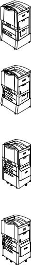
This printer is available in five configurations, as described below:
HP Color LaserJet 8550
The HP Color LaserJet 8550 comes standard with a 100-sheet tray 1, a 500-sheet tray 3, a printer stand, and 32 MB RAM.
HP Color LaserJet 8550N
The HP Color LaserJet 8550N comes standard with a 100-sheet tray 1, a 500-sheet tray 2, a 500-sheet tray 3, a printer stand, 32 MB RAM, an HP JetDirect print server (10/100 Base-TX), and an internal hard disk.
HP Color LaserJet 8550DN
The HP Color LaserJet 8550DN comes standard with a 100-sheet tray 1, a 500-sheet tray 2, a 500-sheet tray 3, a (tray 4) 2,000-sheet input tray, a duplexer, 64 MB RAM, an HP JetDirect print server (10/100 Base-TX), an internal hard disk, and five stabilizing legs.
HP Color LaserJet 8550GN
The HP Color LaserJet 8550GN comes standard with a 100-sheet tray 1, a 500-sheet tray 2, a 500-sheet tray 3, a (tray 4) 2,000-sheet input tray, a duplexer, 128 MB RAM, an HP JetDirect print server (10/100 Base-TX), an internal hard disk, five stabilizing legs, and a higher performance processor.
2 |
EN |

HP Color LaserJet 8550MFP
The HP Color LaserJet 8550MFP comes standard with a 100-sheet tray 1, a 500-sheet tray 2, a 500-sheet tray 3, a duplexer, 64 MB RAM, an HP JetDirect print server (10/100 Base-TX), an internal hard disk, a printer/copy module stand, and a copy module.
EN |
Printer Information 3 |
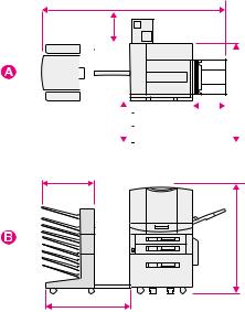
Step 1: Preparing a Location for the Printer
Figure 1
69.8 in (177.3 cm)
11.4 in
(29.0 cm)
|
|
|
|
|
|
|
|
|
|
|
|
|
|
|
|
|
|
|
|
|
|
|
|
|
|
|
|
|
|
|
|
|
|
|
|
|
|
|
|
|
|
|
|
|
|
|
|
|
|
|
|
|
|
|
|
|
|
|
|
|
|
|
|
|
18.1 in |
|
|
|
|
|
|
|
|
||||
|
14.3 in |
|
|
|||||||||
(46.0 cm) |
|
|
|
|
||||||||
|
|
(36.3 cm) |
|
|||||||||
|
|
|
|
|
|
|
|
|||||
|
|
|
|
|
|
|
|
|
|
|
|
|
19.5 in (49.5 cm)
33 in (83.8 cm)
cm) 57.(123 in 65.48 cm) 2.(105 in 4.41
ATop View (with optional multi-bin mailbox and tray 4)
BFront View (with optional multi-bin mailbox and tray 4)
This printer requires the following:
zSpace around the printer, as shown above
zSturdy, level floor surface
zA well-ventilated room without abrupt humidity or temperature changes
zAn area with a recommended temperature range of 68° to 79° F (20° to 26° C), or an allowed temperature range of 59° to 86° F (15° to 30° C)
zAn area with a recommended humidity range of 20% to 50% relative humidity (RH), or an allowed humidity range of 10% to 80% RH
zLine voltage and frequency not varying more than 10% from the value stated on the printer regulatory label (located on the back of the printer)
4 |
EN |
Step 2: Unpacking the Printer
CAUTION
Figure 2
Note
Do not plug the printer into a power source until all shipping material is removed. This may cause damage to the printer.
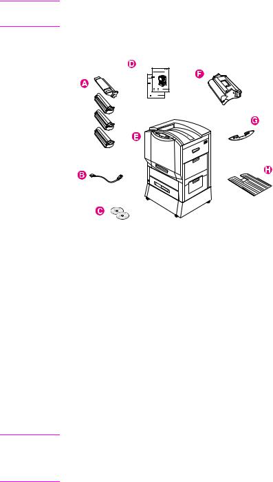
The following items are included with the printer:
AToner cartridges: black, cyan, magenta, and yellow
BPower cord
CSoftware on CD-ROM
DManuals: getting started guide (this guide) and quick reference guide; the online user guide is on a CD-ROM
EPrinter— shown with standard printer stand; some printer models include a 2,000-sheet input tray (tray 4) that replaces the printer stand; a tray 2 is also included with some printer models
FImaging drum
GControl panel overlay (if applicable)
HLeft (face-up) output bin
If the printer model you ordered includes a 2,000-sheet input tray (tray 4), a power pack (containing power connections for the printer and tray 4), a preinstalled interface cable (connecting tray 4 to the printer), and five stabilizing legs are also included.
EN |
Step 2: Unpacking the Printer 5 |

To unpack the printer
1Remove all external packing tape from the printer.
2Open the lower left door and push down the green lever on the right side of the fuser. Then, remove the orange shipping notice from the fuser.
3Open the front door.
6 |
EN |
4Remove the orange packing material from the lower (green) lever.
5Press the white button on the lower (green) lever and swing the lever to the right.
6Remove the packing material from inside the printer and then swing the lower (green) lever back to the left, making sure the lever clicks into place.
7Firmly grip the handle in the center of tray 3, squeeze the release lever, and pull the tray out until it stops. Then remove the orange packing spacers from inside the tray and close the tray.
8If the printer comes with a tray 2, repeat step 7 to remove the orange packing spacers from tray 2
If the printer came with a tray 4, continue with step 9. If the printer came with a stand, proceed to step 16.
EN |
Step 2: Unpacking the Printer 7 |
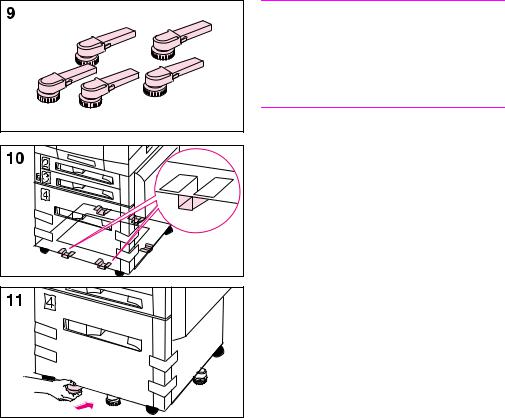
Note
Follow steps 9-12 to attach the five stabilizing legs to the bottom of tray 4. If the five stabilizing legs (which are in addition to the four locking wheels) are already attached, proceed to step 13.
9 Locate the five stabilizing legs that came with the printer.
10 Locate the five guides for the stabilizing legs on the bottom of tray 4— two guides at the front edge,
one on the right edge, and two on the back edge.
11 Insert a stabilizing leg into one of the guides and push the leg into the guide until it stops.
12 Repeat step 11 above to attach the other four stabilizing legs.
8 |
EN |
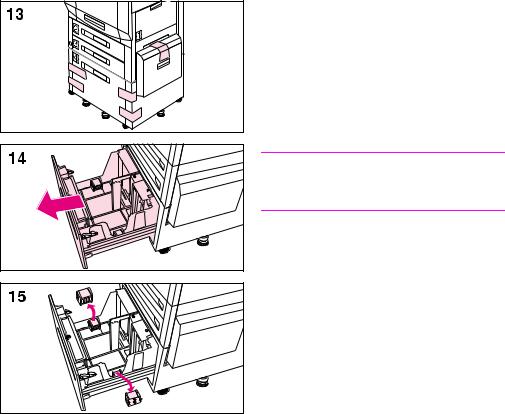
13 Remove the packing tape from tray 4.
14Firmly grip the handle in the center of tray 4, squeeze the release lever, and pull the tray out until it stops.
15Remove the two orange packing clips from inside tray 4 by squeezing the sides of the clips and pulling them out.
CAUTION
Leaving the orange clips in tray 4 can damage the tray.
16 Close all doors and input trays.
By completing steps 1 through 16 above, all tape and spacers should be removed and unpacking of the printer should be complete.
EN |
Step 2: Unpacking the Printer 9 |

Step 3: Installing the Cables
To connect the power cord to a printer with a stand
Note
Make sure that the printer is off (power button out) before connecting the power cord.
1 Roll the printer to its permanent location, where all four wheels rest on a level floor surface, and stabilize it by pushing the locking tabs on the printer stand's wheels to the locked position.
WARNING!
An unstable printer can tip over and cause injury; make sure that the printer is secured properly.
2 Plug the female end of the power cord into the connector on the back left corner of the printer.
3 Plug the male end of the power cord into a surge protector or other grounded power source.
10 |
EN |
To connect the interface cable and power cords for a printer with an optional tray 4
Note
Make sure that the printer is off (power button out) before attaching the interface cable and connecting the power cords.
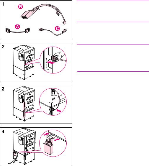
1Locate the interface cable (A), the power pack (B), and the straight power cord (C).
Note
The interface cable (A) might already be attached to the printer and tray 4. If it is, proceed to step 4 below; otherwise, continue with step 2.
2Attach the end of the interface cable that is marked with one dot to the printer above the parallel connector.
3Attach the other end of the interface cable (marked with two dots) to the connector on tray 4 that is marked with two dots.
4Attach the power pack to the back of the printer by inserting the clip into the space between the printer and tray 4.
EN |
Step 3: Installing the Cables 11 |

5Push the two cables extending from the power pack into the space between the printer and tray 4 along the back of the printer.
6Plug the shorter of the two cables into the connector on the back left corner of the printer.
7Plug the longer of the two cables into the connector on the back left corner of tray 4.
8Plug the female end of the power cord into the male connector on the bottom of the power pack.
12 |
EN |
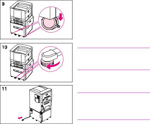
9Roll the printer to its permanent location, where all four wheels rest on a level floor surface, and stabilize it by pushing the locking tabs on the tray's wheels to the locked position.
10Rotate the feet of the five stabilizing legs and the anti-tip foot (on the left side of the tray) until they are snug against the floor.
WARNING!
An unstable printer can tip over and cause injury; make sure that the printer is secured properly.
11 Plug the male end of the power cord into a surge protector or other grounded power source.
Note
If an optional output device was ordered, see the installation guide included with the output device for installation instructions.
EN |
Step 3: Installing the Cables 13 |
Step 4: Connecting the Printer to the Network
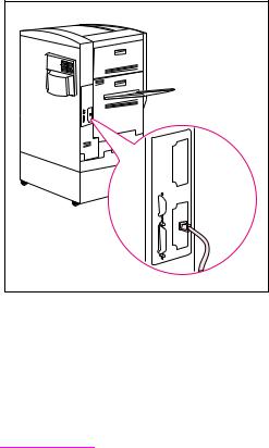
If you will connect the computer to the printer with a parallel cable, see “To connect a parallel cable” later in this Step.
If the printer was shipped with an optional HP JetDirect 10/100TX internal print server for 10Base-T or 100Base-TX networks, the RJ-45 (unshielded twisted pair) card is installed.
To connect to a 10Base-T or 100Base-TX network
Plug the connector of the unshielded twisted-pair network cable into the RJ-45 port. The other end of the cable should be attached to the network.
Note |
The RJ-45 cable is not included with the printer. It must be purchased |
|
separately. |
|
|
14 |
EN |
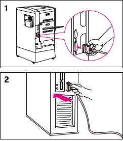
To connect a parallel cable
To print through the parallel port, the printer requires a 25-pin male/micro 36-pin male (“C-size”) parallel cable that is IEEE-1284 compliant. The cable is not included with the printer. It must be purchased separately.
1Squeeze the clips on the micro 36-pin end of the parallel cable and plug it into the printer's parallel port. Release the clips.
2Plug the other end of the parallel cable into the computer. Tighten the screws on the parallel cable to secure the cable to the computer.
EN |
Step 4: Connecting the Printer to the Network 15 |
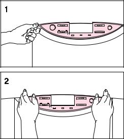
Step 5: Changing the Printer Control Panel Overlay and Language (Optional)
Replace the printer control panel overlay with the one included for your language, if applicable. Then configure the printer control panel to show printer messages in your language.
To replace the overlay
1 Insert a thumbnail or a thin, rigid object under the edge of the overlay on the printer control panel and pull up on the overlay until it comes off.
2 Place the new overlay over the printer control panel and snap it into place.
16 |
EN |
 Loading...