


HP Compaq Business PC Hardware
Reference Guide
Elite 8300 Series Convertible Minitower
Elite 8300 Series Microtower
Elite 8300 Series Small Form Factor
Elite 8300 Series Ultra-Slim Desktop
© Copyright 2012 Hewlett-Packard Development Company, L.P. The information contained herein is subject to change without notice.
Microsoft, Windows, and Windows Vista are either trademarks or registered trademarks of Microsoft Corporation in the United States and/or other countries.
The only warranties for HP products and services are set forth in the express warranty statements accompanying such products and services. Nothing herein should be construed as constituting an additional warranty. HP shall not be liable for technical or editorial errors or omissions contained herein.
This document contains proprietary information that is protected by copyright. No part of this document may be photocopied, reproduced, or translated to another language without the prior written consent of Hewlett-Packard Company.
HP Compaq Business PC Hardware
Reference Guide
Elite 8300 Series Convertible Minitower
Elite 8300 Series Microtower
Elite 8300 Series Small Form Factor
Elite 8300 Series Ultra-Slim Desktop
First Edition (March 2012)
Document part number: 686563–001

About This Book
This guide provides basic information for upgrading HP Compaq Business PCs.
 WARNING! Text set off in this manner indicates that failure to follow directions could result in bodily harm or loss of life.
CAUTION: Text set off in this manner indicates that failure to follow directions could result in damage to equipment or loss of information.
 NOTE: Text set off in this manner provides important supplemental information.
iii
iv About This Book

Table of contents
1 Product Features ............................................................................................................................................ |
1 |
Standard Configuration Features ......................................................................................................... |
1 |
Convertible Minitower (CMT) Front Panel Components ....................................................................... |
3 |
Microtower (MT) Front Panel Components .......................................................................................... |
4 |
Small Form Factor (SFF) Front Panel Components ............................................................................. |
5 |
Ultra-Slim Desktop (USDT) Front Panel Components ......................................................................... |
6 |
Convertible Minitower (CMT) Rear Panel Components ....................................................................... |
7 |
Microtower (MT) Rear Panel Components ........................................................................................... |
8 |
Small Form Factor (SFF) Rear Panel Components ............................................................................. |
9 |
Ultra-Slim Desktop (USDT) Rear Panel Components ........................................................................ |
10 |
Media Card Reader Components ....................................................................................................... |
11 |
Keyboard ............................................................................................................................................ |
12 |
Using the Windows Logo Key ............................................................................................ |
13 |
Serial Number Location ...................................................................................................................... |
14 |
2 Convertible Minitower (CMT) Hardware Upgrades .................................................................................... |
17 |
Serviceability Features ....................................................................................................................... |
17 |
Warnings and Cautions ...................................................................................................................... |
17 |
Removing the Computer Access Panel .............................................................................................. |
18 |
Replacing the Computer Access Panel .............................................................................................. |
19 |
Removing the Front Bezel .................................................................................................................. |
20 |
Removing Bezel Blanks ..................................................................................................................... |
21 |
Replacing the Front Bezel .................................................................................................................. |
22 |
System Board Connections ................................................................................................................ |
23 |
Installing Additional Memory .............................................................................................................. |
24 |
DIMMs ............................................................................................................................... |
24 |
DDR3-SDRAM DIMMs ...................................................................................................... |
24 |
Populating DIMM Sockets ................................................................................................. |
25 |
Installing DIMMs ................................................................................................................ |
26 |
Removing or Installing an Expansion Card ........................................................................................ |
28 |
Drive Positions ................................................................................................................................... |
32 |
Removing a Drive from a Drive Bay ................................................................................................... |
33 |
Installing Drives .................................................................................................................................. |
37 |
Installing a 5.25-inch Drive into a Drive Bay ...................................................................... |
38 |
Installing a Hard Drive into an Internal Drive Bay .............................................................. |
41 |
Changing from a Minitower to a Desktop Configuration ..................................................................... |
45 |
v
Changing from a Desktop to a Minitower Configuration ..................................................................... |
47 |
Installing a Security Lock .................................................................................................................... |
50 |
Cable Lock ......................................................................................................................... |
50 |
Padlock .............................................................................................................................. |
50 |
HP Business PC Security Lock .......................................................................................... |
51 |
Front Bezel Security .......................................................................................................... |
55 |
3 Microtower (MT) Hardware Upgrades ......................................................................................................... |
57 |
Serviceability Features ....................................................................................................................... |
57 |
Warnings and Cautions ...................................................................................................................... |
57 |
Removing the Computer Access Panel .............................................................................................. |
58 |
Replacing the Computer Access Panel .............................................................................................. |
59 |
Removing the Front Bezel .................................................................................................................. |
60 |
Removing Bezel Blanks ..................................................................................................................... |
60 |
Replacing the Front Bezel .................................................................................................................. |
61 |
System Board Connections ................................................................................................................ |
62 |
Installing Additional Memory .............................................................................................................. |
63 |
DIMMs ............................................................................................................................... |
63 |
DDR3-SDRAM DIMMs ...................................................................................................... |
63 |
Populating DIMM Sockets ................................................................................................. |
63 |
Installing DIMMs ................................................................................................................ |
64 |
Removing or Installing an Expansion Card ........................................................................................ |
66 |
Drive Positions ................................................................................................................................... |
70 |
Installing and Removing Drives .......................................................................................................... |
71 |
Removing a 5.25-inch or 3.5-inch Drive from a Drive Bay ................................................. |
73 |
Installing a 5.25-inch or 3.5-inch Drive into a Drive Bay .................................................... |
75 |
Removing a Hard Drive from a Drive Bay .......................................................................... |
78 |
Installing a Hard Drive into an Internal Drive Bay .............................................................. |
79 |
Installing a Security Lock .................................................................................................................... |
83 |
Cable Lock ......................................................................................................................... |
83 |
Padlock .............................................................................................................................. |
83 |
HP Business PC Security Lock .......................................................................................... |
84 |
Front Bezel Security .......................................................................................................... |
88 |
4 Small Form Factor (SFF) Hardware Upgrades ........................................................................................... |
90 |
Serviceability Features ....................................................................................................................... |
90 |
Warnings and Cautions ...................................................................................................................... |
90 |
Removing the Computer Access Panel .............................................................................................. |
91 |
Replacing the Computer Access Panel .............................................................................................. |
92 |
Removing the Front Bezel .................................................................................................................. |
93 |
Removing Bezel Blanks ..................................................................................................................... |
93 |
vi
Replacing the Front Bezel .................................................................................................................. |
94 |
Changing from Desktop to Tower Configuration ................................................................................ |
95 |
System Board Connections ................................................................................................................ |
96 |
Installing Additional Memory .............................................................................................................. |
97 |
DIMMs ............................................................................................................................... |
97 |
DDR3-SDRAM DIMMs ...................................................................................................... |
97 |
Populating DIMM Sockets ................................................................................................. |
97 |
Installing DIMMs ................................................................................................................ |
98 |
Removing or Installing an Expansion Card ...................................................................................... |
101 |
Drive Positions ................................................................................................................................. |
105 |
Installing and Removing Drives ........................................................................................................ |
106 |
Removing a 5.25-inch Drive from a Drive Bay ................................................................. |
108 |
Installing a 5.25-inch Drive into a Drive Bay .................................................................... |
110 |
Removing a 3.5-inch Drive from a Drive Bay ................................................................... |
113 |
Installing a 3.5-inch Drive into a Drive Bay ...................................................................... |
115 |
Removing and Replacing the Primary 3.5-inch Internal Hard Drive ................................ |
117 |
Installing a Security Lock .................................................................................................................. |
121 |
Cable Lock ....................................................................................................................... |
121 |
Padlock ............................................................................................................................ |
121 |
HP Business PC Security Lock ........................................................................................ |
122 |
Front Bezel Security ........................................................................................................ |
126 |
5 Ultra-Slim Desktop (USDT) Hardware Upgrades ...................................................................................... |
128 |
Serviceability Features ..................................................................................................................... |
128 |
Warnings and Cautions .................................................................................................................... |
128 |
Connecting the Power Cord ............................................................................................................. |
129 |
Removing the Computer Access Panel ............................................................................................ |
130 |
Replacing the Computer Access Panel ............................................................................................ |
131 |
Removing the Front Bezel ................................................................................................................ |
132 |
Removing a Bezel Blank .................................................................................................................. |
133 |
Replacing the Front Bezel ................................................................................................................ |
133 |
Changing from Desktop to Tower Configuration .............................................................................. |
134 |
System Board Connections .............................................................................................................. |
135 |
Installing Additional Memory ............................................................................................................ |
136 |
SODIMMs ........................................................................................................................ |
136 |
DDR3-SDRAM SODIMMs ............................................................................................... |
136 |
Populating SODIMM Sockets .......................................................................................... |
137 |
Installing SODIMMs ......................................................................................................... |
138 |
Replacing the Optical Drive .............................................................................................................. |
140 |
Removing the Optical Drive ............................................................................................. |
140 |
Preparing the New Optical Drive ..................................................................................... |
141 |
vii
Installing the New Optical Drive ....................................................................................... |
142 |
Replacing the Hard Drive ................................................................................................................. |
143 |
Installing and Removing a Port Cover .............................................................................................. |
147 |
Installing a Security Lock .................................................................................................................. |
148 |
Cable Lock ....................................................................................................................... |
148 |
Padlock ............................................................................................................................ |
149 |
HP Business PC Security Lock ........................................................................................ |
149 |
Front Bezel Security ........................................................................................................ |
153 |
Appendix A Battery Replacement ................................................................................................................ |
155 |
Appendix B Removing and Replacing a Removable 3.5-inch SATA Hard Drive ..................................... |
158 |
Appendix C Unlocking the Smart Cover Lock ............................................................................................ |
163 |
Smart Cover FailSafe Key ................................................................................................................ |
163 |
Using the Smart Cover FailSafe Key to Remove the Smart Cover Lock ......................................... |
163 |
Appendix D Electrostatic Discharge ............................................................................................................ |
166 |
Preventing Electrostatic Damage ..................................................................................................... |
166 |
Grounding Methods .......................................................................................................................... |
166 |
Appendix E Computer Operating Guidelines, Routine Care and Shipping Preparation ......................... |
167 |
Computer Operating Guidelines and Routine Care .......................................................................... |
167 |
Optical Drive Precautions ................................................................................................................. |
168 |
Operation ......................................................................................................................... |
168 |
Cleaning ........................................................................................................................... |
168 |
Safety ............................................................................................................................... |
168 |
Shipping Preparation ........................................................................................................................ |
168 |
Index ................................................................................................................................................................. |
169 |
viii

1 Product Features
Standard Configuration Features
Features may vary depending on the model. For a complete listing of the hardware and software installed in the computer, run the diagnostic utility (included on some computer models only).
Figure 1-1 Convertible Minitower Configuration


 NOTE: The HP Compaq Convertible Minitower computer can be easily converted to a desktop. For more information, see Changing from a Minitower to a Desktop Configuration on page 45 in this guide.
Figure 1-2 Microtower Configuration
Standard Configuration Features |
1 |
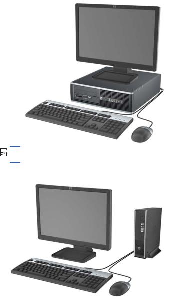
Figure 1-3 Small Form Factor Configuration


 NOTE: The Small Form Factor computer can also be used in a tower orientation. For more information, see Changing from Desktop to Tower Configuration on page 95 in this guide.
Figure 1-4 Ultra-Slim Desktop Configuration
2 Chapter 1 Product Features
Convertible Minitower (CMT) Front Panel Components
Drive configuration may vary by model. Some models have a bezel blank covering one or more drive bays.
Figure 1-5 Front Panel Components
Table 1-1 Front Panel Components
1 |
5.25-inch Optical Drives |
5 |
Microphone/Headphone Connector |
|
|
|
|
2 |
5.25-inch Media Card Reader (optional) |
6 |
Power On Light |
|
|
|
|
3 |
Dual-State Power Button |
7 |
Headphone Connector |
|
|
|
|
4 |
Hard Drive Activity Light |
8 |
USB (Universal Serial Bus) Ports |
NOTE: When a device is plugged into the Microphone/Headphone Connector, a dialog box will pop up asking if you want to use the connector for a microphone Line-In device or a headphone. You can reconfigure the connector at any time by double-clicking the Realtek HD Audio Manager icon in the Windows taskbar.
NOTE: The Power On Light is normally green when the power is on. If it is flashing red, there is a problem with the computer and it is displaying a diagnostic code. Refer to the Maintenance and Service Guide to interpret the code.
Convertible Minitower (CMT) Front Panel Components |
3 |
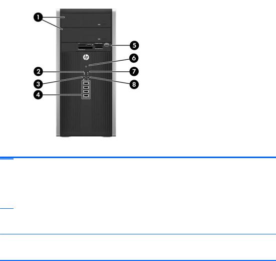
Microtower (MT) Front Panel Components
Drive configuration may vary by model. Some models have a bezel blank covering one or more drive bays.
Table 1-2 Front Panel Components
1 |
5.25-inch Optical Drives |
5 |
3.5-inch Media Card Reader (optional) |
|
|
|
|
2 |
Hard Drive Activity Light |
6 |
Dual-State Power Button |
|
|
|
|
3 |
Microphone/Headphone Connector |
7 |
Power On Light |
|
|
|
|
4 |
USB (Universal Serial Bus) 2.0 Ports |
8 |
Headphone Connector |
NOTE: When a device is plugged into the Microphone/Headphone Connector, a dialog box will pop up asking if you want to use the connector for a microphone Line-In device or a headphone. You can reconfigure the connector at any time by double-clicking the Realtek HD Audio Manager icon in the Windows taskbar.
NOTE: The Power On Light is normally green when the power is on. If it is flashing red, there is a problem with the computer and it is displaying a diagnostic code. Refer to the Maintenance and Service Guide to interpret the code.
4 Chapter 1 Product Features
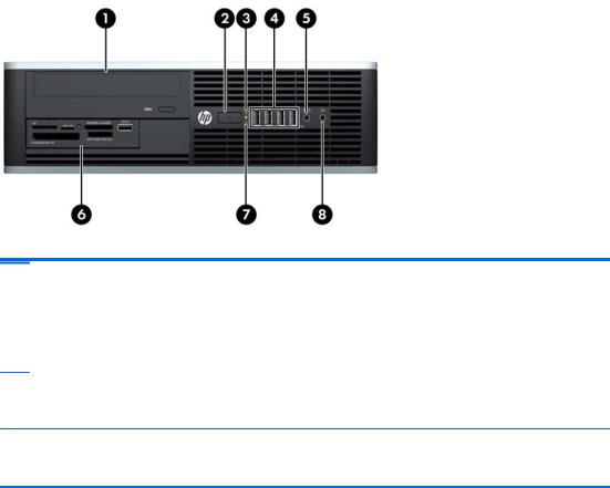
Small Form Factor (SFF) Front Panel Components
Drive configuration may vary by model. Some models have a bezel blank covering one or more drive bays.
Figure 1-6 Front Panel Components
Table 1-3 Front Panel Components
1 |
5.25-inch Optical Drive |
5 |
Microphone/Headphone Connector |
|
|
|
|
2 |
Dual-State Power Button |
6 |
3.5-inch Media Card Reader (optional) |
|
|
|
|
3 |
Power On Light |
7 |
Hard Drive Activity Light |
|
|
|
|
4 |
USB (Universal Serial Bus) Ports |
8 |
Headphone Connector |
NOTE: When a device is plugged into the Microphone/Headphone Connector, a dialog box will pop up asking if you want to use the connector for a microphone Line-In device or a headphone. You can reconfigure the connector at any time by double-clicking the Realtek HD Audio Manager icon in the Windows taskbar.
NOTE: The Power On Light is normally green when the power is on. If it is flashing red, there is a problem with the computer and it is displaying a diagnostic code. Refer to the Maintenance and Service Guide to interpret the code.
Small Form Factor (SFF) Front Panel Components |
5 |
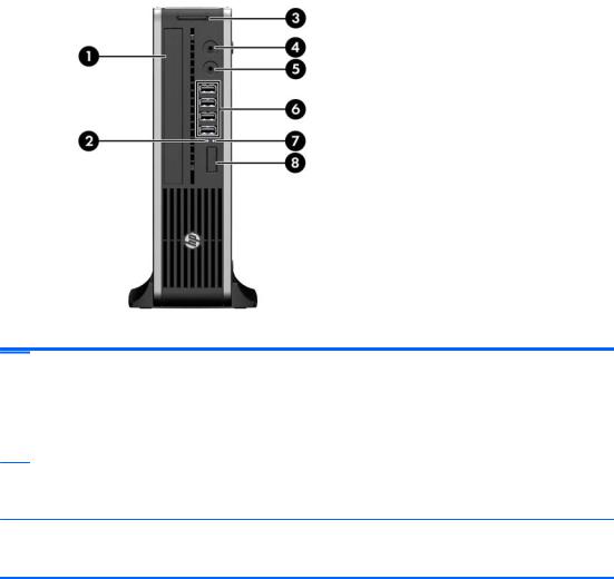
Ultra-Slim Desktop (USDT) Front Panel Components
Drive configuration may vary by model. Some models have a bezel blank covering the optical drive bay.
Figure 1-7 Front Panel Components
Table 1-4 Front Panel Components
1 |
Optical Drive |
5 |
Microphone/Headphone Connector |
|
|
|
|
2 |
Power On Light |
6 |
USB (Universal Serial Bus) Ports |
|
|
|
|
3 |
SD Media Card Reader (optional) |
7 |
Hard Drive Activity Light |
|
|
|
|
4 |
Headphone Connector |
8 |
Dual-State Power Button |
NOTE: When a device is plugged into the Microphone/Headphone Connector, a dialog box will pop up asking if you want to use the connector for a microphone Line-In device or a headphone. You can reconfigure the connector at any time by double-clicking the Realtek HD Audio Manager icon in the Windows taskbar.
NOTE: The Power On Light is normally green when the power is on. If it is flashing red, there is a problem with the computer and it is displaying a diagnostic code. Refer to the Maintenance and Service Guide to interpret the code.
6 Chapter 1 Product Features
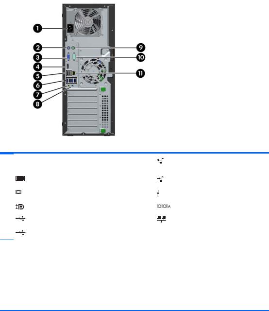
Convertible Minitower (CMT) Rear Panel Components
Figure 1-8 Rear Panel Components
Table 1-5 Rear Panel Components
1 |
Power Cord Connector |
7 |
Line-Out Connector for powered audio |
|
|
|
devices (green) |
|
|
|
|
2 |
PS/2 Keyboard Connector (purple) |
8 |
Line-In Audio Connector (blue) |
|
|
|
|
3 |
VGA Monitor Connector |
9 |
PS/2 Mouse Connector (green) |
|
|
|
|
4 |
DisplayPort Monitor Connector |
10 |
Serial Connector |
|
|
|
|
5 |
USB 2.0 ports |
11 |
RJ-45 Network Connector |
|
|
|
|
6 |
USB 3.0 ports |
|
|
NOTE: An optional second serial port and an optional parallel port are available from HP.
When a device is plugged into the blue Line-In Audio Connector, a dialog box will pop up asking if you want to use the connector for a line-in device or a microphone. You can reconfigure the connector at any time by doubleclicking the Realtek HD Audio Manager icon in the Windows taskbar.
The monitor connectors on the system board are inactive when a graphics card is installed in the computer.
If a graphics card is installed into one of the system board slots, the connectors on the graphics card and the system board may be used at the same time. Some settings may need to be changed in Computer Setup to use both connectors.
Convertible Minitower (CMT) Rear Panel Components |
7 |
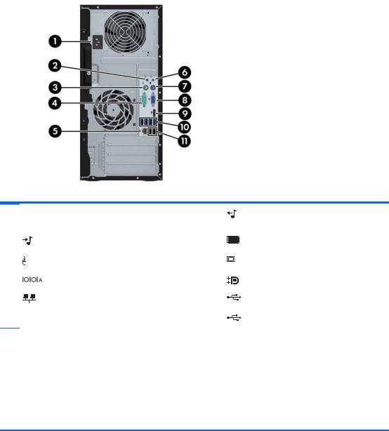
Microtower (MT) Rear Panel Components
Figure 1-9 Rear Panel Components
Table 1-6 Rear Panel Components
1 |
Power Cord Connector |
6 |
Line-Out Connector for powered audio |
|
|
|
devices (green) |
|
|
|
|
2 |
Line-In Audio Connector (blue) |
7 |
PS/2 Keyboard Connector (purple) |
|
|
|
|
3 |
PS/2 Mouse Connector (green) |
8 |
VGA Monitor Connector |
|
|
|
|
4 |
Serial Connector |
9 |
DisplayPort Monitor Connector |
|
|
|
|
5 |
RJ-45 Network Connector |
10 |
USB 3.0 ports |
|
|
|
|
|
|
11 |
USB 2.0 ports |
NOTE: An optional second serial port and an optional parallel port are available from HP.
When a device is plugged into the blue Line-In Audio Connector, a dialog box will pop up asking if you want to use the connector for a line-in device or a microphone. You can reconfigure the connector at any time by doubleclicking the Realtek HD Audio Manager icon in the Windows taskbar.
The monitor connectors on the system board are inactive when a graphics card is installed in the computer.
If a graphics card is installed into one of the motherboard slots, the connectors on the graphics card and the system board may be used at the same time. Some settings may need to be changed in Computer Setup to use both connectors.
8 Chapter 1 Product Features
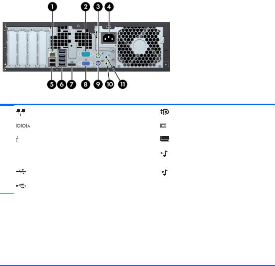
Small Form Factor (SFF) Rear Panel Components
Figure 1-10 Rear Panel Components
Table 1-7 Rear Panel Components
1 |
RJ-45 Network Connector |
7 |
DisplayPort Monitor Connector |
|
|
|
|
2 |
Serial Connector |
8 |
VGA Monitor Connector |
|
|
|
|
3 |
PS/2 Mouse Connector (green) |
9 |
PS/2 Keyboard Connector (purple) |
|
|
|
|
4 |
Power Cord Connector |
10 |
Line-Out Connector for powered audio |
|
|
|
devices (green) |
|
|
|
|
5 |
USB 2.0 ports |
11 |
Line-In Audio Connector (blue) |
|
|
|
|
6 |
USB 3.0 ports |
|
|
NOTE: An optional second serial port and an optional parallel port are available from HP.
When a device is plugged into the blue Line-In Audio Connector, a dialog box will pop up asking if you want to use the connector for a line-in device or a microphone. You can reconfigure the connector at any time by doubleclicking the Realtek HD Audio Manager icon in the Windows taskbar.
The monitor connectors on the system board are inactive when a graphics card is installed in the computer.
If a graphics card is installed into one of the motherboard slots, the connectors on the graphics card and the system board may be used at the same time. Some settings may need to be changed in Computer Setup to use both connectors.
Small Form Factor (SFF) Rear Panel Components |
9 |
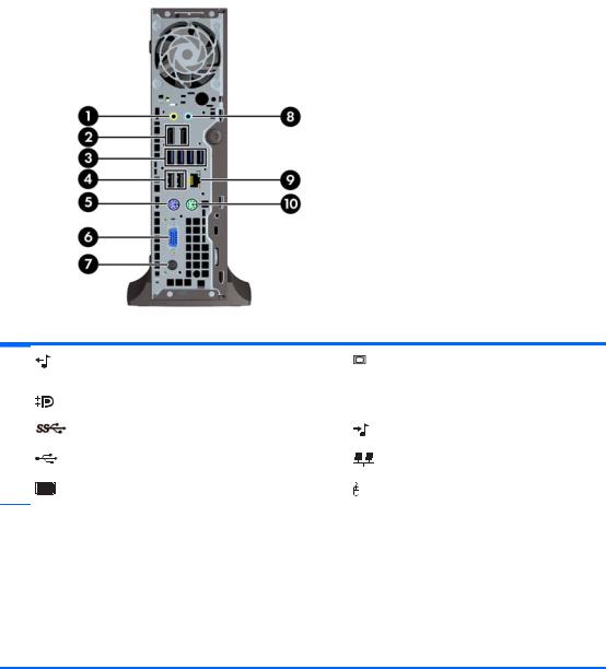
Ultra-Slim Desktop (USDT) Rear Panel Components
Figure 1-11 Rear Panel Components
Table 1-8 Rear Panel Components
1 |
Line-Out Connector for powered audio |
6 |
VGA Monitor Connector |
|
devices (green) |
|
|
|
|
|
|
2 |
DisplayPort Monitor Connectors |
7 |
Power Cord Connector |
|
|
|
|
3 |
USB 3.0 ports |
8 |
Line-In Audio Connector (blue) |
|
|
|
|
4 |
USB 2.0 ports |
9 |
RJ-45 Network Connector |
|
|
|
|
5 |
PS/2 Keyboard Connector (purple) |
10 |
PS/2 Mouse Connector (green) |
NOTE: If an MXM graphics card is installed, all three monitor ports are active. The integrated graphics operate DisplayPort2 (top port). The MXM/ATI drivers operate DisplayPort1 (bottom port) and VGA. If the integrated graphics are disabled in the BIOS settings, DisplayPort2 (top port) will not be active.
If an MXM graphics card is not installed, all three monitor ports are driven by the integrated graphics. Due to a limitation with the Intel integrated graphics, when a DisplayPort to DVI or HDMI adapter is installed, the VGA port will not be active.
When a device is plugged into the blue Line-In Audio Connector, a dialog box will pop up asking if you want to use the connector for a line-in device or a microphone. You can reconfigure the connector at any time by doubleclicking the Realtek HD Audio Manager icon in the Windows taskbar.
10 Chapter 1 Product Features
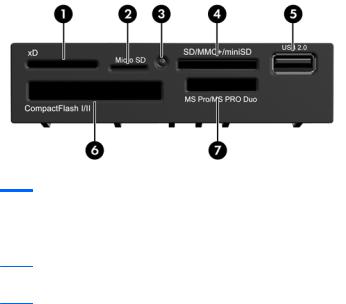
Media Card Reader Components
The media card reader is an optional device available on some models only. Refer to the following illustration and table to identify the media card reader components.
Figure 1-12 Media Card Reader Components
Table 1-9 Media Card Reader Components
No. |
Slot |
Media |
|
|
|
|
|
|
|
1 |
xD |
● |
xD-Picture Card (xD) |
|
|
|
|
|
|
2 |
MicroSD |
● |
MicroSD (T-Flash) |
● MicroSDHC |
3Media Card Reader Activity Light
4 |
SD/MMC+/miniSD |
● |
Secure Digital (SD) |
● |
MiniSDHC |
● |
MultiMediaCard 4.0 |
|
|
● |
Secure Digital High |
● |
MultiMediaCard |
|
(MMC Plus) |
|
|
● |
|
||||
|
|
|
Capacity (SDHC) |
|
(MMC) |
Reduced Size |
|
|
|
● |
MiniSD |
● |
Reduced Size |
|
MultiMediaCard 4.0 |
|
|
|
(MMC Mobile) |
||||
|
|
|
|
|
MultiMediaCard (RS |
|
|
|
|
|
|
|
● |
|
|
|
|
|
|
|
MMC) |
MMC Micro (adapter |
|
|
|
|
|
|
|
|
required) |
|
|
|
|
|
|
|
|
5 |
USB |
● |
USB (Universal Serial |
|
|
|
|
|
|
|
Bus) Port |
|
|
|
|
|
|
|
|
|
|
|
|
6 |
CompactFlash I/II |
● |
CompactFlash Card |
● |
CompactFlash Card |
● |
MicroDrive |
|
|
|
Type 1 |
|
Type 2 |
|
|
|
|
|
|
|
|
|
|
7 |
MS PRO/MS PRO DUO |
● |
Memory Stick (MS) |
● |
Memory Stick Select |
● |
Memory Stick PRO |
|
|
● |
MagicGate Memory |
● |
Memory Stick Duo |
|
Duo (MS PRO Duo) |
|
|
● |
|
||||
|
|
|
Stick (MG) |
|
(MS Duo) |
Memory Stick PRO- |
|
|
|
● |
MagicGate Memory |
● |
Memory Stick PRO |
|
HG Duo |
|
|
● |
|
||||
|
|
|
Duo |
|
(MS PRO) |
Memory Stick Micro |
|
|
|
|
|
|
|
|
(M2) (adapter |
|
|
|
|
|
|
|
required) |
|
|
|
|
|
|
|
|
Media Card Reader Components 11
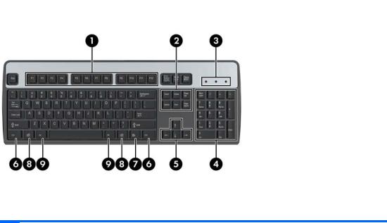
Keyboard
Figure 1-13 Keyboard Components
Table 1-10 Keyboard Components
1 |
Function Keys |
Perform special functions depending on the software application being used. |
|
|
|
2 |
Editing Keys |
Includes the following: Insert, Home, Page Up, Delete, End, and Page Down. |
|
|
|
3 |
Status Lights |
Indicate the status of the computer and keyboard settings (Num Lock, Caps |
|
|
Lock, and Scroll Lock). |
|
|
|
4 |
Numeric Keys |
Work like a calculator keypad. |
|
|
|
5 |
Arrow Keys |
Used to navigate through a document or Web site. These keys allow you to |
|
|
move left, right, up, and down, using the keyboard instead of the mouse. |
|
|
|
6 |
Ctrl Keys |
Used in combination with another key; their effect depends on the application |
|
|
software you are using. |
|
|
|
7 |
Application Key1 |
Used (like the right mouse button) to open pop-up menus in a Microsoft Office |
|
|
application. May perform other functions in other software applications. |
|
|
|
8 |
Windows Logo Keys1 |
Used to open the Start menu in Microsoft Windows. Used in combination with |
|
|
other keys to perform other functions. |
|
|
|
9 |
Alt Keys |
Used in combination with another key; their effect depends on the application |
|
|
software you are using. |
|
|
|
1 |
Keys available in select geographic regions. |
|
12 Chapter 1 Product Features
Using the Windows Logo Key
Use the Windows Logo key in combination with other keys to perform certain functions available in the Windows operating system. Refer to Keyboard on page 12 to identify the Windows Logo key.
Table 1-11 Windows Logo Key Functions
The following Windows Logo Key functions are available in Microsoft Windows XP, Microsoft Windows Vista, and Microsoft Windows 7.
Windows Logo Key |
Displays or hides the Start menu |
|
|
Windows Logo Key + d |
Displays the Desktop |
|
|
Windows Logo Key + m |
Minimizes all open applications |
|
|
Shift + Windows Logo Key + m |
Undoes Minimize All |
|
|
Windows Logo Key + e |
Launches My Computer |
|
|
Windows Logo Key + f |
Launches Find Document |
|
|
Windows Logo Key + Ctrl + f |
Launches Find Computer |
|
|
Windows Logo Key + F1 |
Launches Windows Help |
|
|
Windows Logo Key + l |
Locks the computer if you are connected to a network domain, |
|
or allows you to switch users if you are not connected to a |
|
network domain |
|
|
Windows Logo Key + r |
Launches the Run dialog box |
|
|
Windows Logo Key + u |
Launches the Utility Manager |
|
|
Windows Logo Key + Tab |
Windows XP - Cycles through the Taskbar buttons |
|
Windows Vista and Windows 7 - Cycles through programs on |
|
the Taskbar using the Windows Flip 3-D |
In addition to the Windows Logo Key functions described above, the following functions are also available in Microsoft Windows Vista and Windows 7.
Ctrl + Windows Logo Key + Tab |
Use the arrow keys to cycle through programs on the Taskbar |
|
by using Windows Flip 3-D |
|
|
Windows Logo Key + Spacebar |
Brings all gadgets to the front and select Windows Sidebar |
|
|
Windows Logo Key + g |
Cycles through Sidebar gadgets |
|
|
Windows Logo Key + t |
Cycles through programs on the taskbar |
|
|
Windows Logo Key + u |
Launches Ease of Access Center |
|
|
Windows Logo Key + any number key |
Launches the Quick Launch shortcut that is in the position that |
|
corresponds to the number (for example, Windows Logo Key + 1 |
|
launches the first shortcut in the Quick Launch menu) |
In addition to the Windows Logo Key functions described above, the following functions are also available in Microsoft Windows 7.
Windows Logo Key + Ctrl + b |
Switches to the program that displayed a message in the |
|
notification area |
|
|
Windows Logo Key + p |
Choose a presentation display mode |
|
|
Windows Logo Key + up arrow |
Maximizes the window |
|
|
Windows Logo Key + left arrow |
Snaps the window to the left side of the screen |
|
|
Keyboard 13
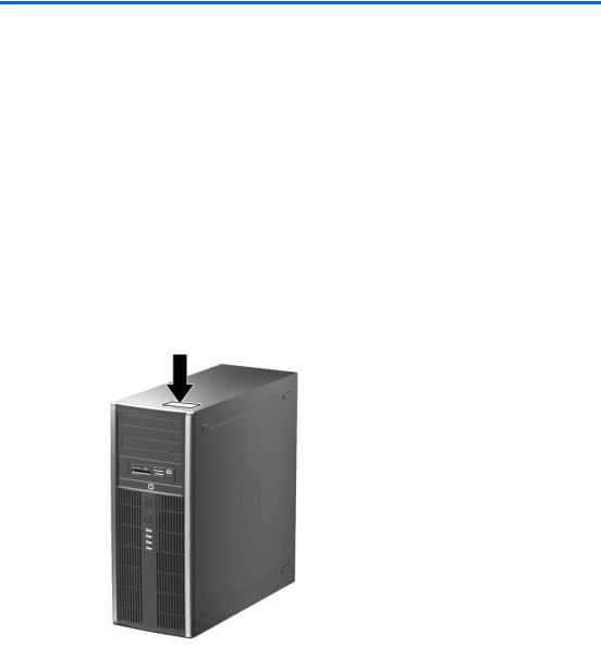
Table 1-11 Windows Logo Key Functions (continued)
Windows Logo Key + right arrow |
Snaps the window to the right side of the screen |
|
|
Windows Logo Key + down arrow |
Minimizes the window |
|
|
Windows Logo Key + Shift + up arrow |
Stretches the window to the top and bottom of the screen |
|
|
Windows Logo Key + Shift + left arrow or right |
Moves a window from one monitor to another |
arrow |
|
|
|
Windows Logo Key + + (on numpad) |
Zooms in |
|
|
Windows Logo Key + - (on numpad) |
Zooms out |
|
|
Serial Number Location
Each computer has a unique serial number and a product ID number that are located on the top cover of the computer. Keep these numbers available for use when contacting customer service for assistance.
Figure 1-14 Convertible Minitower Serial Number and Product ID Location
14 Chapter 1 Product Features

Figure 1-15 Microtower Serial Number and Product ID Location
Figure 1-16 Small Form Factor Serial Number and Product ID Location
Serial Number Location 15
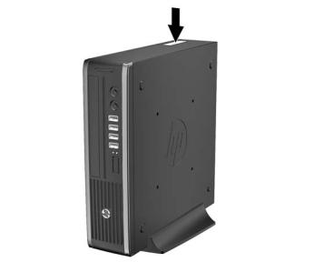
Figure 1-17 Ultra-Slim Desktop (USDT) Serial Number and Product ID Location
16 Chapter 1 Product Features

2Convertible Minitower (CMT) Hardware Upgrades
Serviceability Features
The computer includes features that make it easy to upgrade and service. No tools are needed for most of the installation procedures described in this chapter.
Warnings and Cautions
Before performing upgrades be sure to carefully read all of the applicable instructions, cautions, and warnings in this guide.
 WARNING! To reduce the risk of personal injury from electrical shock, hot surfaces, or fire:
Disconnect the power cord from the wall outlet and allow the internal system components to cool before touching.
Do not plug telecommunications or telephone connectors into the network interface controller (NIC) receptacles.
Do not disable the power cord grounding plug. The grounding plug is an important safety feature.
Plug the power cord in a grounded (earthed) outlet that is easily accessible at all times.
To reduce the risk of serious injury, read the Safety & Comfort Guide. It describes proper workstation, setup, posture, and health and work habits for computer users, and provides important electrical and mechanical safety information. This guide is located on the Web at http://www.hp.com/ergo.
 WARNING! Energized and moving parts inside.
Disconnect power to the equipment before removing the enclosure.
Replace and secure the enclosure before re-energizing the equipment.
 CAUTION: Static electricity can damage the electrical components of the computer or optional equipment. Before beginning these procedures, ensure that you are discharged of static electricity by briefly touching a grounded metal object. See Electrostatic Discharge on page 166 for more information.
When the computer is plugged into an AC power source, voltage is always applied to the system board. You must disconnect the power cord from the power source before opening the computer to prevent damage to internal components.
Serviceability Features 17
Removing the Computer Access Panel
To access internal components, you must remove the access panel:
1.Remove/disengage any security devices that prohibit opening the computer.
2.Remove all removable media, such as compact discs or USB flash drives, from the computer.
3.Turn off the computer properly through the operating system, then turn off any external devices.
4.Disconnect the power cord from the power outlet and disconnect any external devices.
 CAUTION: Regardless of the power-on state, voltage is always present on the system board as long as the system is plugged into an active AC outlet. You must disconnect the power cord to avoid damage to the internal components of the computer.
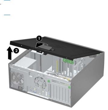
5.Lift up on the access panel handle (1) then lift the access panel off the computer (2).
Figure 2-1 Removing the Computer Access Panel
18 Chapter 2 Convertible Minitower (CMT) Hardware Upgrades
Replacing the Computer Access Panel
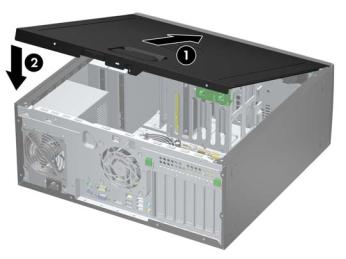
Slide the lip on the front end of the access panel under the lip on the front of the chassis (1) then press the back end of the access panel onto the unit so that it locks into place (2).
Figure 2-2 Replacing the Computer Access Panel
Replacing the Computer Access Panel 19
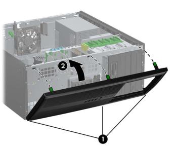
Removing the Front Bezel
1.Remove/disengage any security devices that prohibit opening the computer.
2.Remove all removable media, such as compact discs or USB flash drives, from the computer.
3.Turn off the computer properly through the operating system, then turn off any external devices.
4.Disconnect the power cord from the power outlet and disconnect any external devices.
 CAUTION: Regardless of the power-on state, voltage is always present on the system board as long as the system is plugged into an active AC outlet. You must disconnect the power cord to avoid damage to the internal components of the computer.
5.Remove the computer access panel.
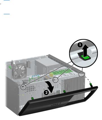
6.Lift up the three tabs on the side of the bezel (1), then rotate the bezel off the chassis (2).
Figure 2-3 Removing the Front Bezel
20 Chapter 2 Convertible Minitower (CMT) Hardware Upgrades
Removing Bezel Blanks
On some models, there are bezel blanks covering the 5.25-inch drive bays that need to be removed before installing a drive. To remove a bezel blank:
1.Remove the access panel and front bezel.
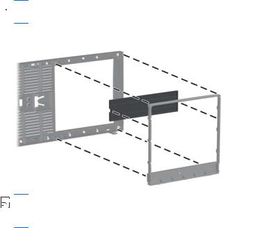
2.Gently pull the subpanel, with the bezel blanks secured in it, away from the front bezel, then remove the desired bezel blank.
 CAUTION: Hold the subpanel straight when you pull it away from the front bezel. Pulling the subpanel away at an angle could damage the pins that align it within the front bezel.
Figure 2-4 Removing Bezel Blanks from the Subpanel (Desktop Shown)


 NOTE: When replacing the subpanel, ensure that the aligning pins and any remaining bezel blanks are in their proper orientation. The logo on the subpanel should be located at the bottom of the subpanel when properly oriented.
Removing Bezel Blanks 21
Replacing the Front Bezel
Insert the three hooks on the bottom side of the bezel into the rectangular holes on the chassis (1) then rotate the top side of the bezel onto the chassis (2) and snap it into place.
Figure 2-5 Replacing the Front Bezel
22 Chapter 2 Convertible Minitower (CMT) Hardware Upgrades
 Loading...