


Model B132L/B132L+/B160L/B180L
Owner’s Guide
HP Part No. A4190-90023
Edition E0997
Printed in U.S.A.
ã Hewlett-Packard Co. 1997
Printing History
First Printing: Septermber 1997
UNIX is a registered trademark in the United States and other countries, licensed exclusively through X/Open Company Limited.
NOTICE
The information contained in this document is subject to change without notice.
HEWLETT-PACKARD MAKES NO WARRANTY OF ANY KIND WITH REGARD TO THIS MATERIAL INCLUDING BUT NOT LIMITED TO THE IMPLIED WARRANTIES OF MERCHANTABILITY AND FITNESS FOR A PARTICULAR PURPOSE. Hewlett-Packard shall not be liable for errors contained herein or for incidental or consequential damages in connection with the furnishing, performance or use of this material.
Hewlett-Packard assumes no responsibility for the use or reliability of its software on equipment that is not furnished by Hewlett-Packard.
This document contains proprietary information that is protected by copyright. All rights reserved. No part of this document may be photocopied, reproduced or translated to another language without the prior written consent of Hewlett-Packard Company.
RESTRICTED RIGHTS LEGEND. Use, duplication, or disclosure by government is subject to restrictions as set forth in subdivision (c) (1) (ii) of the Rights in Technical Data and Computer Software Clause at DFARS 252.227.7013. Hewlett-Packard Co., 3000 Hanover St., Palo Alto, CA 94304.
10 9 8 7 6 5 4 3 2 1

Contents
Preface 1
Audience 2
Safety and Regulatory Statements 2
Release Document(s) 2
Related Manuals 3
Revision History 3
Documentation Conventions 4
Problems, Questions, and Suggestions 5
1 System Overview
Product Description |
9 |
|
|
|
System Unit Front Panel Controls and LEDs 11 |
||||
System Power Switch |
12 |
|
||
Power LED |
12 |
|
|
|
System LEDs |
12 |
|
|
|
Audio Controls 13 |
|
|
||
Removable Storage Devices |
13 |
|||
System Unit Rear Panel Connectors 14 |
||||
Security Loop |
15 |
|
|
|
Audio Connectors |
15 |
|
|
|
Keyboard Connectors |
17 |
|
||
PS/2 Keyboard and Mouse Connectors 17 |
||||
HP Parallel I/O Connector |
17 |
|||
802.3 Network Connectors |
17 |
|||
Serial I/O Connectors |
18 |
|
||
SCSI Connectors |
18 |
|
|
|
TOC Button |
19 |
|
|
|
iii

Contents
Power Cord Connector |
19 |
|
||
Monitors |
20 |
|
|
|
Keyboard |
20 |
|
|
|
Pointing Devices 20 |
|
|
||
Operating System Overview 21 |
|
|||
Important Information You Need to Record |
22 |
|||
LANIC ID 22 |
|
|
||
IP Address and Subnetwork Mask Information |
23 |
|||
Networking Overview |
24 |
|
||
24 |
|
|
||
telnet 24 |
|
|
||
rlogin |
24 |
|
|
|
ftp |
25 |
|
|
|
rcp |
25 |
|
|
|
NFS |
25 |
|
|
|
2 Using Your CD-ROM Drive
CD-ROM Drive and CD-ROM Media Descriptions 29
CD-ROM Drive 29
Controls and Features 30
CD-ROM Media 32
Caring for CD-ROM Discs 32
Operating the CD-ROM Drive 33
Loading and Unloading a CD-ROM in the Disc Tray 33 |
|
|
Disc Tray Description 33 |
|
|
Loading a CD-ROM Disc in a Horizontally Mounted Drive |
34 |
|
Unloading a CD-ROM Disc in a Horizontally Mounted Drive |
35 |
|
Loading a CD-ROM Disc in a Vertically Mounted Drive |
36 |
|
Unloading a CD-ROM Disc in a Vertically Mounted Drive |
38 |
|
iv

Contents
Verifying the CD-ROM Drive Operation 39
Mounting and Unmounting a CD-ROM Disc 40
Mounting a CD-ROM Disc Using SAM 40
Unmounting a CD-ROM Disc Using SAM 42
Reading the Busy Light 43
Troubleshooting 45
3 Using Your Digital Data Storage (DDS) Tape Drive
DDS Tape Drive and Data Cassette Descriptions 49 |
|||
DDS Drive 49 |
|
|
|
Storage Capacities |
49 |
|
|
Controls and Indicators |
50 |
||
LEDs 51 |
|
|
|
LED Warning Conditions |
52 |
||
Data Cassettes |
53 |
|
|
Media Life |
53 |
|
|
Cleaning the Tape Heads |
54 |
||
Media Restrictions |
54 |
|
|
Setting the Write-Protect Tab on a Data Cassette 55 |
|||
Operating the DDS Tape Drive 56 |
|
Loading and Unloading a Data Cassette |
56 |
Verifying the DDS Tape Drive Operation |
57 |
Using Device Files 58 |
|
Archiving Data 59 |
|
Writing to a Data Cassette 59 |
|
Restoring Files from a Data Cassette to Your System 60 Listing the Files on a Data Cassette 60
Further Command Information 61
Troubleshooting 62
Ordering Information 62
v

Contents
4 Using Your 3.5-Inch Floppy Disk Drive
Using the Floppy Diskette |
65 |
|
|
Setting the Write-Protect Tab on a Diskette |
65 |
||
Inserting and Removing a Diskette |
66 |
|
|
Operating the Floppy Drive |
67 |
|
|
Verifying the Floppy Drive Configuration |
67 |
||
Using Device Files 68 |
|
|
|
Formatting a New Diskette |
69 |
|
|
Transferring Data To and From a Floppy Diskette 70 |
|||
Saving Files to a Floppy Diskette |
70 |
|
|
Restoring Files from a Floppy Diskette to Your System 70 Listing the Files on a Floppy Diskette 71
For More Information 72
Configuring the Floppy Driver 73
Troubleshooting 74
Ordering Information 74
5 Solving Problems
Common Problems and Solutions 77
Problems with Powering Up the System |
77 |
|
Problems Loading and Booting the Operating System 78 |
||
Problems with the 802.3 Network 79 |
|
|
Problems Using a Hard Disk Drive |
80 |
|
Problems Using the CD-ROM Drive |
81 |
|
Problems Using the DDS Tape Drive |
82 |
|
Problems Using the Floppy Disk Drive |
83 |
|
LED Error Codes 84 |
|
|
Dealing with a Boot Failure 87 |
|
|
Running System Verification Tests |
88 |
|
vi

Contents
Device Verification 90
ASafety and Regulatory Statements
Declaration of Conformity 1 93 Declaration of Conformity 2 94
Special Video Configuration Statements 95
For EN55022 or CISPR 22 Applications: 95
Emissions Regulations 96
Federal Communications Commission (FCC) 96
VCCI Class 2 ITE 97
97
Emissions Regulations Compliance 98
Acoustics 99
Regulation On Noise Declaration For Machines -3. GSGV 99
Electrostatic Discharge (ESD) Precautions 100
Safety Statement 101
Laser Safety Statement (U.S.A. Only) 102
Visible LEDs 102
Warnings and Cautions 103
BChanging Your Workstation’s Hardware Configuration
Checking the SCSI IDs 107 Preparing Your Workstation 109
vii

Contents
Removing the Main Tray Assembly |
111 |
|
|||
Replacing the Main Tray Assembly |
112 |
|
|||
Installing Storage Devices |
114 |
|
|
|
|
Preparing to Install Your Storage Device 115 |
|
||||
Configuring your Storage Device |
|
115 |
|
||
Determining Your Storage Devices Position 115 |
|
||||
Removing the Storage Tray |
117 |
|
|
|
|
Removing the Storage Tray Cover |
120 |
|
|||
Installing a CD-ROM or a DDS-Format Tape Drive 121 |
|
||||
Installing a Floppy Drive |
123 |
|
|
|
|
Installing a Hard Disk Drive in Position 2 (Front Position) |
126 |
||||
Installing a Hard Disk Drive in Position 1 (Rear Position) |
131 |
||||
Replacing the Storage Tray Cover |
132 |
|
|||
Replacing the Storage Tray |
133 |
|
|
|
|
Configuring a Hard Disk Drive |
135 |
|
|
|
|
Installing Additional memory |
137 |
|
|
||
Removing Memory Modules |
138 |
|
|
|
|
Installing Memory Modules |
141 |
|
|
|
|
Removing Cache Boards 144
Installing Second Level Cache Boards 146
Installing a PCI, EISA, or GSC Option Board 148
Graphics Adapter Considerations 149
Special Video Configuration Statements 149
Graphics Paths 150
Graphics Configuration Restrictions 150
Installing the Option Board 151
Replacing the Battery 155
Installing the Optional EGRAM (Enhanced Graphics RAM) Module 161 Installing the Optional Fast Wide Differential SCSI Controller 163
viii

Contents
Changing Your Monitor Type 168
Setting the Monitor Type from the Boot Console Interface 168 Setting the Monitor Type at Power On 168
Changing the Console to External Terminal 169
CSCSI Connections
SCSI Bus Differences 173
SCSI Restrictions 175
Cables 175
Connectors and Terminators 177
SCSI Configuration Constraints 177
Narrow-SE SCSI Bus Configuration Constraints 177
Fast Wide Differential SCSI Bus Configuration Constraints 178 Ultra, Wide Single-Ended SCSI Bus Configuration Constraints 179
Determining SCSI Bus Length |
180 |
|
NSE SCSI Bus Length |
180 |
|
FWD SCSI Bus Length |
181 |
|
Ultra, Wide-SE SCSI Bus Length 182 |
||
Assigning SCSI Device IDs 184 |
||
NSE SCSI Device IDs |
185 |
|
FWD SCSI IDs 187 |
|
|
Ultra, Wide-SE SCSI IDs 188 |
|
|
Connecting to the SCSI Ports |
190 |
|
SCSI Port Connection |
190 |
|
DThe Boot Console Interface
Boot Console Interface Features 195 Accessing the Boot Console Interface 200
ix

Contents
Booting Your Workstation |
201 |
|
|
|
|
||
Searching for Bootable Media |
203 |
|
|
|
|
||
Resetting Your Workstation |
204 |
|
|
|
|
||
Displaying and Setting Paths |
205 |
|
|
|
|
||
Displaying and Setting the Monitor Type |
208 |
|
|||||
The Monitor Command |
208 |
|
|
|
|
|
|
Displaying the Current Monitor Configuration |
209 |
||||||
Setting the Monitor Type |
210 |
|
|
|
|
||
Setting the Monitor Type at Power On |
212 |
|
|
||||
Changing the Console to External Terminal |
|
213 |
|
||||
Displaying the Current Memory Configuration |
214 |
||||||
Memory Information Sample 1 |
215 |
|
|
|
|
||
Displaying the Status of the System I/O |
216 |
|
|||||
Setting the Auto Boot and Auto Search Flags |
217 |
||||||
Displaying and Setting the Security Mode |
219 |
||||||
Displaying and Setting the Fastboot Mode |
220 |
||||||
Displaying the LAN Station Address |
221 |
|
|
||||
Configure and Display LAN Settings (B132L+/B180L Only) 222 |
|||||||
Displaying System Information 224 |
|
|
|
|
|||
Displaying PIM Information |
225 |
|
|
|
|
||
x
Contents
Figures
System Unit Front Panel Controls 11
System Unit Rear Panel Connectors 14
CD-ROM Drive Controls and Features 30
CD-ROM Disc Tray 33
Placing a CD-ROM Disc in a Horizontally Mounted Drive 34 Removing a CD-ROM Disc From a Horizontally Mounted Drive 35 Releasing the Disc Holder Retainers 36
Placing a CD-ROM Disc in a Vertically Mounted Drive 37 Removing a CD-ROM Disc From a Vertically Mounted Drive 38 DDS-DC (Early Model) Drive Controls and Indicators 50 DDS-DC (Later Model) Drive Controls and Indicators 50 DDS-2 Drive Controls and Indicators 50
DDS-DC (Early Model) Tape Drive LED Display Codes 51
DDS-DC (Later Model) and DDS-2 Tape Drive LED Display Codes 52 Setting the Write-Protect Tab on a DDS Tape 55
Loading and Unloading a Data Cassette 56
Setting the Write-Protect Tab on a Floppy Diskette 65 Inserting and Removing a Floppy Diskette 66
System Unit Front Panel LEDs 84
Removing the Floor Stand 110
Removing Main Tray Assembly 111
Replacing the Main Tray Assembly 112
Disk Tray Positions (Side View) 116
Removing the Memory Retainer 117
Disconnecting the Storage Tray Assembly 118
Removing the Storage Tray Assembly 119
Removing the Storage Tray Cover 120
Removing a Disk Filler Panel 121
Installing a CD-ROM or DDS Tape 122
xi

Contents
Removing the Floppy Filler Panel 123
Installing the Floppy Disk Drive 124
Connecting the Floppy Drive Data Cable 125
Disconnecting the Floppy Drive Cable 126
Removing the Floppy Disk Drive Assembly 127
Installing a Hard Disk Drive in Position 2 (Front Position) 128 Replacing the Floppy Drive and Carrier 129
Connecting the Floppy Drive Data Cable 130
Installing a Hard Disk Drive in Position 1 (Rear Position) 131 Replacing the Storage Tray Cover 132
Installing the Storage Tray Assembly 133
Connecting the Storage Tray Cables 134
Memory Module Location 138
Removing the Memory Retainer 139
Removing a Memory Module 140
Memory Module Location 141
Removing the Memory Retainer 142
Installing Memory Modules 143
Cache Boards Location 144
Removing a Cache Board 145
Cache Boards Location 146
Installing Cache Boards 147
Option Slots from Outside the System Unit 148
Removing the Option Board Support Bracket and Blank Plate 151 Installing a PCI, EISA, or GSC Option Board 152
Removing the PCI Adapter 153
Replacing the Option Board Support Bracket 154
Removing the Memory Retainer 155
Disconnecting the Storage Tray Assembly 156
Removing the Storage Tray Assembly 157
xii

Contents
Removing the Battery 158
Installing the Storage Tray Assembly 159
Connecting the Storage Tray Cables 160 Installing the Optional EGRAM Module 161 Installing the Optional FWD SCSI Controller 163 Removing the Storage Tray Cover 164 Removing the Blank Plate 165
Installing the FWD SCSI Cable 166
Replacing the Storage Tray Cover 167
Rear Panel SCSI Connectors without Terminators 190
xiii

Contents
Tables
Audio Electrical Specifications 16
Serial I/O Pins 18
Sample LANSCAN COMMAND TABLE 23 CD-ROM Drive Operating Controls and Features 31
DDS Tape Drive Capacities Without Data Compression 49 DDS Tape Drive Capacities With Data Compression 49 Power Up Problems 77
Problems Loading and Booting the Operating System 78 Problems with the 802.3 Network 79
Problems Using a Hard Disk Drive 80
Problems Using the CD-ROM Drive 81
Problems Using the DDS Tape Drive 82
Problems Using the Floppy Disk Drive 83
LED Error Codes 85
Default SCSI IDs 115
Storage Configurations 116
SCSI Bus Differences 173
SCSI Bus Addresses, ID Numbers, and Arbitration Priorities 174 Narrow-SE SCSI Bus Configuration Constraints 178
Fast, Wide Differential SCSI Bus Configuration Constraints 178 Ultra Wide Single-Ended SCSI Bus Configuration Constraints 179 Bus Length Worksheet for NSE SCSI Bus 181
Bus Length Worksheet for FW SCSI Bus 182
Bus Length Worksheet for UW SCSI Bus 183
Single-Ended SCSI Device IDs 186
Fast, Wide SCSI Device Drives and Device ID 188 Ultra Wide SE SCSI Device Drives and Device ID 189 System Paths 205
Mnemonic Style Notation 206
xiv

Preface
1

This owner’s guide describes how to use your HP 9000 B132L/B132L+/ B160L/B180L workstation.
This manual assumes that you have installed your workstation as described in the HP 9000 Model B132L/B160L/B180L Hardware Installation Card.
Audience
This guide is intended for HP 9000 B132L/B132L+/B160L/B180L workstation users.
Safety and Regulatory Statements
See Appendix A in the back of this manual for safety and regulatory statements that apply to this workstation.
Release Document(s)
Please refer to the Release Document(s) you received with your system or system software for additional information that we may not have been able to include in this guide at the time of its publication.
2

Related Manuals
If you are using HP-UX version 10.20, refer to the following manuals for more information:
•HP 9000 Model B132L/B160L/B180L Hardware Installation Card (A419090010)
•Using Your HP Workstation (A2615-90003)
•Installing and Updating HP-UX (B2355-90050)
•Configuring HP-UX for Peripherals (B2355-90053)
•HP Visual User Environment User’s Guide (B1171-90079)
•Managing Clusters of HP 9000 Computers: Sharing the HP-UX File System (B2355-90038)
•HPUX X User Environment User’s Guide
•Precision Architecture RISC HP 9000 Series 700 Diagnostics Manual (9245390010)
To order manuals, please contact your local sales office.
Revision History
The revision history for each edition of the manual is listed below:
HP Part No. |
Edition |
Revision History |
A4190-90023 |
E0997 |
First printing. |
3

Documentation Conventions
Unless otherwise noted in the text, this guide uses the following symbolic conventions.
user-supplied values |
Italic words or characters in for- |
|
|
|
mats and command descriptions |
|
|
represent values that you must |
|
|
supply. |
sample user input |
In examples, information that the |
|
|
|
user enters appears in color. |
output |
Information that the system dis- |
|
|
|
plays appears in this type- |
|
|
face. |
literal values |
Bold words or characters in for- |
|
|
|
mats and command descriptions |
|
|
represent commands or keywords |
|
|
that you must use literally. Path- |
|
|
names are also in bold. |
|
Text with a line above and a line |
|
KEY |
|
|
|
|
below denotes a key on your key- |
|
|
board, or a key or button which is |
|
|
drawn on your workstation’s |
|
|
graphic display. |
|
|
(In this manual we refer to the |
|
|
Enter key. On your keyboard the |
|
|
key may be labeled either Enter |
|
|
or Return.) |
4

Problems, Questions, and Suggestions
If you have any problems, questions, or suggestions with our hardware, software, or documentation, please call 1-888-301-5932 (US & Canada) or contact the HP Response Center for your country.
5

6
1
System Overview
7

System Overview
This chapter introduces the HP 9000 B132L/B132L+/B160L/B180L workstations. Its purpose is to familiarize you with your workstation and its controls and indicators. The information is presented in the following sections:
•Product Description
•System unit front panel controls and LEDs
•System unit rear panel connectors
•Monitors
•Keyboard
•Pointing devices
•Operating system overview
•Important information you need to note
•Networking overview
8

System Overview
Product Description
Product Description
The B Class workstations have the following key features:
•Processor Performance
Model B132L - 132 Mhz (33 Mhz GSC)
Model B132L+ - 132 Mhz (33 Mhz GSC)
Model B160L - 160 Mhz (40 Mhz GSC)
Model B180L - 180 Mhz (36 Mhz GSC)
•Operating System
Model B132L/B160L - Native HP-UX (version 10.20 or greater)
Model B132L+/B180L - Native HP-UX (version 10.20 or greater + ACE)
•User Interface
HP VUE graphical user interface
HP CDE graphical user interface
•Compatibility
Source and binary code compatible with the Series 700 product family
•Optional Graphics:
Model B132L/B160L - HP VISUALIZE-24Z, 24-plane graphics
HP VISUALIZE-8/24, Accelerated 8-plane or 24-plane 3D graphics
Model B132L+/B180L - HP VISUALIZE-8/24/48/48XP
HP VISUALIZE-EG/DualEG
•Main Memory
Model B132L/B160L - 6 slots of main memory allowing 32 to 768 MBytes Model B132L+/B180L - 6 slots of main memory allowing 32 to 768 MBytes
•Second Level Cache
2 slots allowing 1 MB of second level cache
•Internal Storage Devices
3.5-inch Slimline Floppy Disk Drive (not a SCSI Device) Single-Ended SCSI Hard Disks (up to two) Single-Ended SCSI CD-ROM Drive
Single-Ended SCSI 2.0/4.0/8.0 GB, 4-mm DDS-Format Tape Drive Fast, Wide SCSI Hard Disk Drives (requires optional FW SCSI adapter)
9

System Overview
Product Description
Model B132L+/B180L only - Ultra-SCSI 2.0/4.0/9.0 GB Hard Disks
NOTE: On the Model 180L, you can install either Fast, Wide Differential SCSI or Ultra, Wide Single-Ended SCSI, but not both.
•Standard Network
Ethernet IEEE 802.3 AUI
RJ45, UTP Twisted Pair
Model B132L+/B180L only - 10Base T/100Base T
•Standard I/O
SE SCSI Connector - 8-bit,5 MB/sec synchronous 1.5 MB/sec asynchronous 50-pin, high density SCSI connector
Model B132L/B160L - 68-pin, high density Fast, Wide Differential SCSI connector.
Model B132L+/B180L - 68 pin, high density Ultra, Wide Single-Ended SCSI connector.
Two Serial Interfaces RS232C, 9-pin male
One Parallel Interface, Centronics, BUSY handshake 25 pin female Audio Line-in, Line-out, Mic, and Headphone
Two PS/2 ports (Keyboard and Mouse)
•EISA/PCI/GSC Option Slots Slot 1 - GSC or PCI
Slot 2 - EISA, GSC, or PCI
•User Interface
PS/2 Keyboard
PS/2 Mouse
10
System Overview
System Unit Front Panel Controls and LEDs
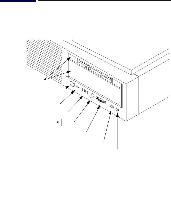
System Unit Front Panel Controls and LEDs
Before powering on your system, you should become familiar with the system unit controls.
Figure 1 shows the system unit front panel controls.
Removable
Storage Devices
 Power Switch
Power LED


 System LEDs
Mute
 Volume
 Headset
 Mic
Mic
Figure 1 |
System Unit Front Panel Controls |
11
System Overview
System Unit Front Panel Controls and LEDs
System Power Switch
Use the Power switch to power the system unit on and off.
NOTICE: There is no need to manually shut down the HP-UX operating system on your workstation before powering it off. When you turn off the power switch, your workstation automatically shuts down the operating system before terminating the power.
Power LED
The Power LED lights when the system unit power is on.
System LEDs
The system LEDs indicate the status of your workstation. In the event of a system problem, the LEDs are lighted in different patterns to indicate error codes. See Chapter 6 for a complete list of the system LED error codes.
LED 4 - System Heartbeat
LED 3 - SCSI Bus Activity
LED 2 - Network Receive
LED 1 - Network Transmit
12

NOTICE:
NOTICE:
System Overview
System Unit Front Panel Controls and LEDs
Audio Controls
Next to the system LEDs are the following audio controls:
Headset Jack |
Accommodates mini-headphones with a 3.5-mm diame- |
|
ter miniature stereo plug. |
Volume Control |
Adjusts the audio output volume to the headset jack or |
|
line out. |
Mic Jack |
Accommodates microphones with a 3.5-mm diameter |
|
miniature stereo plug. |
Mute Button |
Turns off the audio output to line out and speaker only. |
The Volume Control, Headphone Jack, and Mic (microphone) Jack features of the CD-ROM are supported through software applications only.
For more information on the features and electrical specifications, see “Audio Connectors” later in this chapter.
Removable Storage Devices
The Models B132L/B132L+/B160L/B180L support the following removable storage devices:
•CD-ROM Disc Drive
•DDS-Format Tape Drive
•Floppy Diskette Drive
Due to space limitations, a DDS-format tape drive and a CD-ROM drive cannot both be mounted in the system at the same time. Also, adding either a DDS tape or CD-ROM takes on internal drive bay, leaving only one internal drive bay available for a hard disk drive.
A description of each drive’s controls and indicators is in the chapter describing that device, later in this book.
13

System Overview
System Unit Rear Panel Connectors
System Unit Rear Panel Connectors
This section describes the connectors on the system unit’s rear panel
NOTICE: To maintain electro-magnetic and radio frequency emissions compliance, verify that all cables are fully seated and properly fastened.
Figure 2 shows the locations of the connectors on the system unit’s rear panel.
Fast, Wide or Ultra, Wide SCSI 
Single-Ended SCSI 
Monitor
Security Loop
PS/2 Mouse
PS/2 Keyboard 
Pullout Card |
|
|
|
Audio Line In |
|
|
|
|
Audio Line Out |
|
Power |
HP Parallel |
TOC |
|
|
|
|
||
|
|
|
|
|
LAN-TP |
LAN-AUI |
Serial 1 |
|
|
|
|
|
|
|
Serial 2 |
Figure 2 |
System Unit Rear Panel Connectors |
14

System Overview
System Unit Rear Panel Connectors
Security Loop
The security loop provides a means of locking the storage tray, with a padlock or other locking device, to prevent unauthorized removal from the system.
Audio Connectors
Your workstation has audio input and output capability through external input and output connectors on the rear panel and through an internal speaker. The rear panel contains the Audio IN (stereo line-in) and Audio OUT (stereo line-out) connectors.
NOTICE: To maintain compliance with FCC/CISPR B you must use fully shielded, unbalanced audio cables and plugs.
The audio connectors are standard stereo audio mini-jacks. Hewlett-Packard recommends using gold-plated plugs available through audio retailers for best quality recording and playback through the external connectors. The following is a summary of the workstation audio features:
•Audio Features
Programmable sample rates:
8kHz, 16kHz, 32kHz, 48kHz, 11.025kHz, 22.05kHz, and 44.1kHz.
Programmable output attenuation: 0 to -96dB in -1.5dB steps
Programmable input gain:
0 to 22.5dB in 1.5dB steps Input monitoring:
16-bit linear, 8-bit u-law, or A-law coding
•Audio Input
Line In
Mono microphone (on the front panel) compatible with 1.5V phantom supply (bias voltage supplied by the
15

System Overview
System Unit Rear Panel Connectors
system).
CD-ROM audio (if internal CD-ROM is installed)
•Audio Output
Line-out
Headphone (on the front panel)
Built-in mono speaker
•Audio CODEC
Crystal CS4215
The audio electrical specification for this workstation are summarized in Table 1
Table 1 |
Audio Electrical Specifications |
|
|
|
|
|
Frequency Response |
25-20,000 Hz |
|
|
|
|
Input Sensitivity/Impedance |
|
|
Line In |
2.0Vpk/47k ohm |
|
Microphone |
22mVpk/1k ohm |
|
|
|
|
Max Output Level/Impedance |
|
|
Line Out |
2.8Vpp/47k ohm |
|
Headphone |
2.75Vpp/50 ohm |
|
Speaker (internal) |
5.88Vpp/48 ohm |
|
|
|
|
Output Impedance |
|
|
Line Out |
619 ohm |
|
Headphone |
118 ohm |
|
|
|
|
Signal to Noise* |
|
|
Line Out |
65 dB |
|
Headphone |
61 dB |
|
Speaker |
63 dB |
|
Line In |
61 dB |
|
Microphone |
57 dB |
|
|
|
|
THD (w nominal load) |
|
|
Line Out |
-73 dB |
|
Headphone |
-70 dB |
|
Speaker |
-68 dB |
|
Line In |
-75 dB |
16
 Loading...