


Hardware Guide
1Guide to the Printer
2Installing Options
3Connecting the Printer
4Configuration
5Paper and Other Media
6Replacing Consumables
7Adjusting the Printer
8Troubleshooting
9Removing Misfed Paper
10 Appendix
Read this manual carefully before you use this machine and keep it handy for future reference. For safe and correct use, be sure to read the Safety Information before using the machine.
Trademarks
Microsoft, Windows and Windows NT are registered trademarks of Microsoft Corporation in the United States and/or other countries.
Adobe®, PostScript®, Acrobat®, PageMaker® and Adobe Type Manager are registered trademarks of Adobe Systems Incorporated.
PCL® is a registered trademark of Hewlett-Packard Company.
Apple, AppleTalk, EtherTalk, Macintosh, Mac OS, and True Type are trademarks of Apple Computer, Inc., registered in the U.S. and other countries.
IPS-PRINT Printer Language Emulation Copyright© 1999-2000 Oak Technology, Inc., All rights reserved.
NetWare is a registered trademark of Novell, Inc.
Other product names used herein are for identification purposes only and might be trademarks of their respective companies. We disclaim any and all rights to those marks.
The proper names of the Windows operating systems are as follows:
•Microsoft® Windows® 95 operating system
•Microsoft® Windows® 98 operating system
•Microsoft® Windows® Millennium Edition (Windows Me)
•The product names of Windows® 2000 are as follows: Microsoft® Windows® 2000 Advanced Server Microsoft® Windows® 2000 Server
Microsoft® Windows® 2000 Professional
•The product names of Windows® XP are as follows: Microsoft® Windows® XP Professional
Microsoft® Windows® XP Home Edition
•The product names of Windows ServerTM 2003 are as follows: Microsoft® Windows ServerTM 2003 Standard Edition Microsoft® Windows ServerTM 2003 Enterprise Edition Microsoft® Windows ServerTM 2003 Web Edition
•The product names of Windows NT® 4.0 are as follows: Microsoft® Windows NT® Server 4.0
Microsoft® Windows NT® Workstation 4.0
i
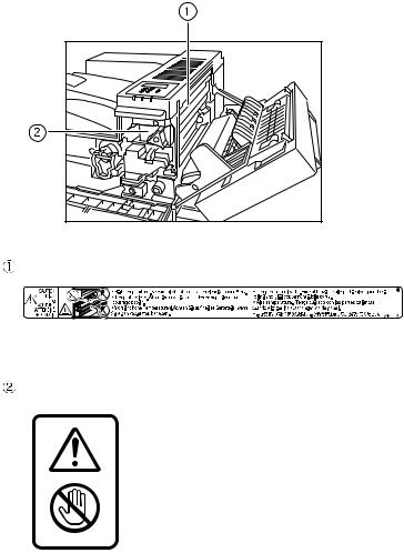
Positions of RWARNING and RCAUTION labels
This machine has labels for RWARNING and RCAUTION at the positions shown below. For safety, please follow the instructions and handle the machine as indicated.
AQV254S |
High temperature parts. Turn off the main power and be careful when replacing fusing unit/removing misfed paper.
The surface of the fusing unit becomes very hot. Do not touch parts labelled “R” (indicating a hot surface). Touching these parts will result in burns.
ii
Manuals for This Printer
For particular functions, see the relevant parts of the manual.
Safety Information
Provides information on safe usage of this machine.
To avoid injury and prevent damage to the machine, be sure to read this.
Quick Installation Guide
Contains procedures for removing the printer from its box, connecting it to a computer, and installing its driver.
Hardware Guide
Contains information about paper and procedures such as installing options, replacing consumables, responding to error messages, and resolving jams.
Software Guide
Contain procedures for using this machine in a network environment, utilizing the software, and using security functions.
iii
How to Read This Manual
Symbols
This manual uses the following symbols:
Indicates important safety notes.
Ignoring these notes could result in serious injury or death. Be sure to read these notes.
They can be found in the "Safety Information".
Indicates important safety notes.
Ignoring these notes could result in moderate or minor injury, or damage to the machine or to property. Be sure to read these notes.
They can be found in the "Safety Information".
Indicates points to pay attention to when using the machine, and explanations of likely causes of paper misfeeds, damage to originals, or loss of data. Be sure to read these explanations.
Indicates supplementary explanations of the machine’s functions, and instructions on resolving user errors.
This symbol is located at the end of sections. It indicates where you can find further relevant information.
[ ]
Indicates the names of keys that appear on the machine’s display panel.
{}
Indicates the names of keys on the machine’s control panel.
iv

Description for the Specified Model
In this manual, the following items explain about the printer for the specified models:
This explains about the 220–240 V model printer.
Read if you purchase this model.
This explains about the 120 V model printer.
Read if you purchase this model.

 Note
Note
You can identify the printer's model by checking the label on its inside as shown.
AQV745S |
v
Installing the Operating Instructions
The CD-ROM “Manuals” provided with the printer contains an HTML Operating Instructions Manual in HTML version. Follow this instructions to install it.
 Important
System Requirements :
•Windows 95/98/Me, Windows 2000/XP, Windows Server 2003 or Windows NT4.0.
•800 × 600 or higher monitor resolution.
Web Browsers :
•Microsoft Internet Explorer 5.5 SP2 or higher
•Firefox 1.0 or higher
A B
Quit all applications currently running.
Insert the CD-ROM “Manuals” into the CD-ROM drive.
The installer starts.
Auto Run may not work under certain operating system setting. If this is the case, launch “Setup.exe” on the CD-ROM root directory.
C D E F G
Select an interface language, and then click [OK].
Click [Install manuals].
Follow the instructions on the screen to complete the installation.
Click [Finish] when the installation is completed.
Click [Exit].

 Note
Note
Auto Run may not work under certain operating system setting. If this is the case, copy all data on the CD-ROM root directory to your hard disk drive, and then launch “Setup.exe” to start the installation.
To uninstall the Operating Instructions Manual, select [Programs] in the [Start] menu, select your printer driver, and then click [uninstall]. You can uninstall each Manual Guide separately.
If you are using an incompatible Web browser and the simpler version of the Operating Instructions Manual does not display correctly, open the folder “MANUALLANG (language)\(manual name)unv” on the CDROM “Manuals”, and then double-click on “index.htm”.
vi

TABLE OF CONTENTS |
|
Trademarks.............................................................................................................. |
i |
Positions of RWARNING and RCAUTION labels .............................................. |
ii |
Manuals for This Printer....................................................................................... |
iii |
How to Read This Manual .................................................................................... |
iv |
Symbols .................................................................................................................... |
iv |
Description for the Specified Model..................................................................... |
v |
Installing the Operating Instructions .................................................................. |
vi |
1. Guide to the Printer |
|
Exterior: Front View............................................................................................... |
1 |
Exterior: Rear View ................................................................................................ |
2 |
Inside....................................................................................................................... |
3 |
Control Panel.......................................................................................................... |
4 |
2. Installing Options |
|
Available Options................................................................................................... |
5 |
Option List .................................................................................................................. |
5 |
Option Installation Flow Chart .................................................................................... |
6 |
Installing Options........................................................................................................ |
7 |
Caution when re-installing the controller board.......................................................... |
9 |
Attaching Paper Feed Unit PB 3020 ................................................................... |
10 |
Attaching User Account Enhance Unit Type E ................................................. |
16 |
Attaching Printer Hard Disk Drive Type 8100.................................................... |
20 |
Attaching Memory Unit Type D 128MB, Memory Unit Type E 256MB (SDRAM |
|
Module) ............................................................................................................... |
27 |
Attaching IEEE 802.11b Interface Unit ............................................................... |
32 |
Attaching IEEE 1284 Interface Board Type A.................................................... |
36 |
Attaching Gigabit Ethernet Board ...................................................................... |
38 |
Attaching VM Card Type D.................................................................................. |
41 |
Attaching Data Storage Card Type A ................................................................. |
43 |
3. Connecting the Printer |
|
Network Connection ............................................................................................ |
45 |
Reading the LED Lamps .......................................................................................... |
47 |
USB Connection................................................................................................... |
48 |
Parallel Connection ............................................................................................. |
49 |
4. Configuration |
|
Ethernet Configuration........................................................................................ |
51 |
Using DHCP - Detecting the Network Address Automatically.................................. |
54 |
Making Network Settings for Using Netware............................................................ |
55 |
IEEE 802.11b (Wireless LAN) Configuration ..................................................... |
57 |
vii

5. Paper and Other Media |
|
Paper and Other Media Supported by This Printer........................................... |
63 |
Paper Recommendations.................................................................................... |
67 |
Loading Paper.......................................................................................................... |
67 |
Storing Paper ........................................................................................................... |
67 |
Types of Paper and Other Media ............................................................................. |
68 |
Paper not supported by this printer .......................................................................... |
69 |
Print Area ................................................................................................................. |
70 |
Loading Paper ...................................................................................................... |
71 |
Loading Paper in Tray 1, Tray 2, and the Optional Paper Feed Unit ....................... |
71 |
Loading Paper in the Optional Large Capacity Tray ................................................ |
74 |
Setting a Paper Size by Using the Control Panel..................................................... |
76 |
Specifying a Paper Type for Tray 1/2 and the Optional Paper Feed Unit ................ |
78 |
Loading Paper in the Bypass Tray ........................................................................... |
79 |
Switching between Paper Trays............................................................................... |
85 |
6. Replacing Consumables |
|
Replacing the Toner Cartridge ........................................................................... |
87 |
Adding Staples..................................................................................................... |
92 |
7. Adjusting the Printer |
|
Adjusting the Image Density............................................................................... |
95 |
Adjusting Tray Registration................................................................................ |
96 |
8. Troubleshooting |
|
Error & Status Messages on the Control Panel ................................................ |
99 |
Printer Does Not Print ....................................................................................... |
101 |
Checking the port connection................................................................................. |
102 |
Other Printing Problems ................................................................................... |
104 |
Additional Troubleshooting .............................................................................. |
109 |
Removing Jammed Staples .............................................................................. |
111 |
Removing Punch Waste .................................................................................... |
114 |
9. Removing Misfed Paper |
|
Removing Misfed Paper .................................................................................... |
117 |
When “Remove Misfeed A,Y:Paper Tray” Appears ............................................... |
118 |
When “Remove Misfeed B,C,D:Inter.Path” Appears.............................................. |
121 |
When “Remove Misfeed R:Finisher” Appears........................................................ |
124 |
When “Remove Misfeed U:LCT” Appears.............................................................. |
127 |
When “Remove Misfeed Z:Duplex Unit” Appears .................................................. |
129 |
viii

10.Appendix |
|
Moving and Transporting the Printer |
...............................................................131 |
Moving the Printer .................................................................................................. |
132 |
Consumables ..................................................................................................... |
133 |
Toner Cartridge ...................................................................................................... |
133 |
Maintenance Kit ..................................................................................................... |
133 |
Specifications..................................................................................................... |
134 |
Mainframe .............................................................................................................. |
134 |
Options................................................................................................................... |
137 |
INDEX....................................................................................................... |
143 |
ix
x
1. Guide to the Printer
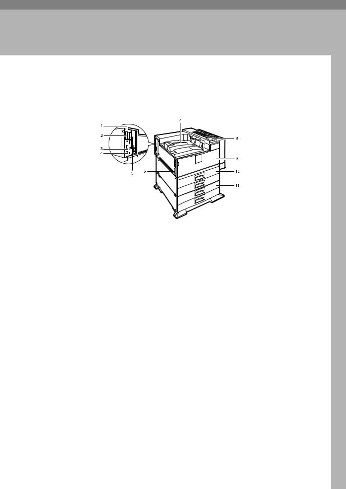
Exterior: Front View
1. Controller Board
Remove this board when installing the hard disk unit, SDRAM modules, or User Account Enhance unit.
2. Optional board slots
Remove the cover when installing the optional board.
3. USB port
AQV002S
7. Output Tray
Printed output is stacked here with the print side face down.
8. Control Panel
Contains keys for printing operation and a panel display that shows the printer status.
9. Front Cover
Use a USB cable to connect the printer to the host computer.
4. Ethernet Port
Open this cover if you replace some parts or if a paper misfeed occurs.
10. Paper Tray
Use a network interface cable to connect the printer to the network.
5. Expansion card slot
Insert an optional unit into a slot.
6. Power Switch
Use this switch to turn the printer power on and off.
Holds up to 550 sheets of plain paper per tray and 1100 sheets in total. (80 g/m2, 20 lb.)
11. Paper Feed Unit PB 3020 (Option)
Holds up to 550 sheets of plain paper per tray and 1100 sheets in total. (80 g/m2, 20 lb.)
1
Guide to the Printer
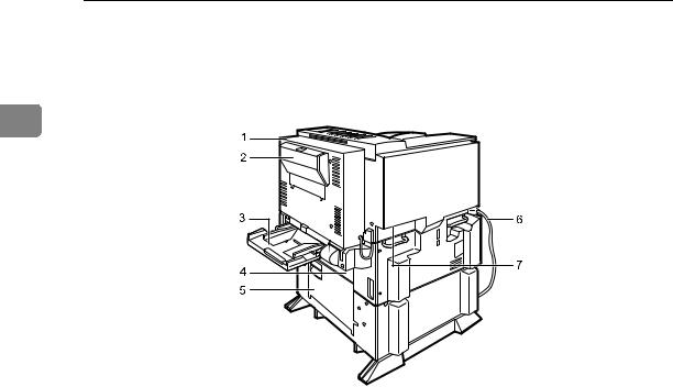
Exterior: Rear View
1
|
AQV031S |
1. Duplex Unit |
5. Lower Vertical Paper Feed Cover |
Allows you to print onto both sides of the paper.
2. Duplex Unit Right Cover
Open this cover when accessing the inside of the printer.
3. Bypass Tray
Holds up to 50 sheets of plain paper. (80 g/m2, 20 lb.)
4. Upper Vertical Paper Feed Cover
Open this cover when accessing the inside of the printer.
6. Power Cord
Plug this cord into a wall outlet.
7. Ventilator
Helps to keep components inside the printer from overheating.
Open this cover when accessing the inside of the printer.
If you install the optional Large Capacity Tray RT45, remove this cover.
2
Inside
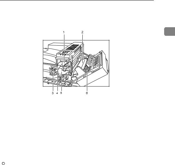
Inside
1
|
AQV005S |
1. Fusing Unit |
4. Toner Holder |
When “Replace Maintenance Kit” appears on the panel display, replace this unit.
2. Transfer Unit
When “Replace Maintenance Kit” appears on the panel display, replace this unit.
3. Toner Lock Handle
Turn up the lever when replacing the toner.

 Reference
Slide this out when replacing the toner.
5. Development Unit
When “Replace Maintenance Kit” appears on the panel display, replace this unit.
6. Right Cover
Open this cover when accessing the inside of the printer.
For details about the messages which appear on the screen to prompt you to replace the units, see p.99 “Error & Status Messages on the Control Panel”.
3
Guide to the Printer
Control Panel
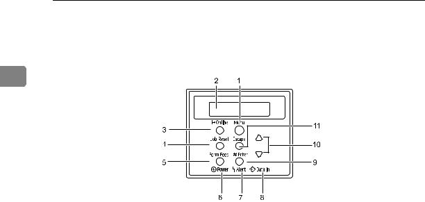
1
1. {Menu} Key
Press this key to make and check the current printer settings.
2. Panel Display
Shows the current status of the printer and error messages.
3. {Online} Key
Press this key to switch the printer between online and offline.
4. {Job Reset} Key
When the printer is online, press this key to cancel any ongoing print job.
See “Canceling a Print job”, Softtware Guide.
5. {Form Feed} Key
If the printer is offline, press this key to print all the data left in the printer's input buffer.
This does not work if the printer is online.
6. Power Indicator
Is on when the printer power is on.
Is off when the power is off or when the printer is in Energy Saver mode.
AQV250S
7. Alert Indicator
Blinks or lights up whenever any printer error occurs. A message describing the cause of the error also appears on the panel display.
8. Data In Indicator
Blinks while the printer is receiving data from a computer.
Is on if there is data to be printed.
9. {qEnter} Key
Press this key to execute menu items selected on the panel display.
Press this key to clear some errors.
10. {U} {T} Keys
Use these keys to increase or decrease values on the panel display when making settings.
11. {Escape} Key
Press this key to return to the previous condition on the panel display.
4
2. Installing Options
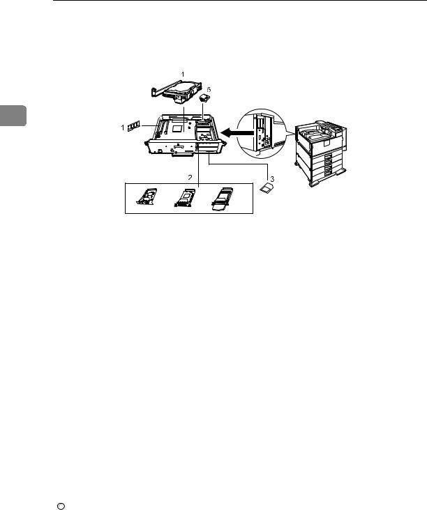
Available Options
This section describes how to install options.
By installing options, you can improve the printer performance and have an expanded variety of features to use. For the specifications of each option, see p.134 “Specifications”.
RCAUTION:
•Before installing options, the machine should be turned off and unplugged for at least an hour. Components inside the machine become very hot, and can cause a burn if touched.
•Before moving the machine, unplug the power cable from the outlet. If the cable is unplugged abruptly, it could become damaged. Damaged plugs or cables can cause an electrical or fire hazard.
•When lifting the machine, use the grips on both sides. The machine could break or cause an injury if dropped.
 Important
The voltage rating of the connector for options is 24 V DC or less.
Option List
The following is a list of options for this printer.
•Finisher SR 3040 *1
•Paper Feed Unit PB 3020 *1
•Large Capacity Tray RT45 *1
•Bridge Unit Type 2045 *1
•Punch Kit Type 1045 *1
•Memory Unit Type D 128MB
•Memory Unit Type E 256MB
•User Account Enhance Unit Type E
•IEEE 802.11b Interface Unit
•IEEE 1284 Interface Board Type A
•Gigabit Ethernet Board Type A
•Printer Hard Disk Drive Type 8100
•VM Card Type D
•Data Storage Card Type A
*1 If you want to install the unit, contact your sales or service representative.
5

Installing Options
Option Installation Flow Chart
Installing multiple options in the following order is recommended:
A Attatch the paper feed unit (Paper Feed Unit PB 3020).
Attach the paper feed unit to the bottom of the printer.
2B C
Take out the controller board from the printer.
Install User Account Enhance Unit (User Account Enhance Unit Type E).
Install the module to the User Account Enhance Unit slot of the controller board.
D Remove all SDRAM modules before installing the hard disk drive.
E Install the hard disk drive (Printer Hard Disk Drive Type 8100).
Install the hard disk drive to the controller board.
F Install the SDRAM module (Memory Unit Type D 128MB, Memory Unit Type E 256MB).
Install the module to the SDRAM module slot on the controller board. There are two types of memory unit: 128 MB and 256 MB.
G Install IEEE 1284 interface board, IEEE 802.11b interface unit, or Gigabit Ethernet board.
Install one of these options into the vacant expansion slot (on the left) of the controller board.
The followings can be installed:
•IEEE 1284 Interface Board Type A
•IEEE 802.11b Interface Unit
•Gigabit Ethernet Board Type A
Do not install more than one option. These options do not function simultaneously.
H Install the VM card (VM Card Type D) or the data storage card (Data Storage Card Type A).
Insert these units into the SD card slot on the controller board.
6
Available Options
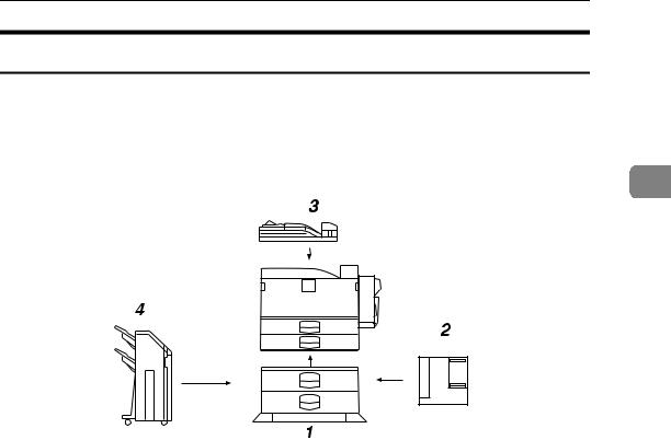
Installing Options
Install options in the positions shown in the illustration.
Exterior
2
AQV017S
1.Paper Feed Unit PB 3020
2.Large Capacity Tray RT45
Holds up to 1500 sheets of plain paper. (80 g/m2, 20 lb.)
If you want to install the Large Capacity Tray RT45, contact your sales or service representative.

 Note
Note
3.Bridge Unit Type 2045
This unit is necessary when using the Finisher.
If you want to install the Bridge Unit Type 2045, contact your sales or service representative.
4.Finisher SR 3040
If you want to install the Finisher SR 3040, contact your sales or service representative.
Bridge Unit Type 2045 is required when you install Finisher SR 3040.
To use the punch function with the Finisher SR 3040, Punch Kit Type 1045 is required.
7
Installing Options
Interior
2
AQV019S
1. Memory Unit Type D 128MB/Memory Unit Type E 256MB (SDRAM module)
Install 128 MB or 256 MB SDRAM module into the controller board slot. See p.27 “Attaching Memory Unit Type D 128MB, Memory Unit Type E 256MB (SDRAM Module)”.
2. Optional boards
See p.32 “Attaching IEEE 802.11b Interface Unit”.
See p.36 “Attaching IEEE 1284 Interface Board Type A”.
See p.38 “Attaching Gigabit Ethernet Board”.

 Note
Note
3.Optional units
See p.41 “Attaching VM Card Type D”.
See p.43 “Attaching Data Storage Card Type A”.
4.Printer Hard Disk Drive Type 8100
See p.20 “Attaching Printer Hard Disk Drive Type 8100”.
5.User Account Enhance Unit Type E
See p.16 “Attaching User Account Enhance Unit Type E”.
You cannot install following options at the same time:
•IEEE 802.11b Interface Unit
•IEEE 1284 Interface Board Type A
•Gigabit Ethernet Board Type A

 Reference
For the specifications of each option, see p.134 “Specifications”.
8

Available Options
Caution when re-installing the controller board
This section describes handling the controller board when installing options.
If you slide out the controller board to install units, carefully read the instruction to re-install the controller board.
Important |
2 |
The following may occur if the controller board is not properly installed: |
•all control panel indicators are lit.
•no control panel indicators is lit.
•the error message appears on the display.
9
Installing Options
Attaching Paper Feed Unit PB 3020
When installing multiple options, install the paper feed unit first.
RCAUTION:
•Before moving the machine, unplug the power cord from the outlet. If the cord is unplugged abruptly, it could become damaged. Damaged plugs or
2 |
cords can cause an electrical or fire hazard. |
•When lifting the machine, use the grips on both sides. The machine could break or cause an injury if dropped.
•When lifting the paper feed unit, hold the bottom of it, and then lift it slowly. Lifting it carelessly or dropping it may cause an injury.
 Important
Before using the new paper feed unit, you must make settings in the printer driver.
Check the printer nameplate to confirm the model code.
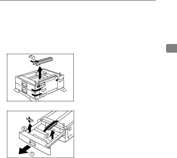
A Check the package contains the following:
Paper Feed Unit PB 3020 |
AQV039S |
1
2
3
AQV720S
1.Screw
2.Knob Screw (Finger type)
3.Lock Plate
10
Attaching Paper Feed Unit PB 3020
B Confirm that the printer is turned off, and the power cord is unplugged from the wall outlet.
C Remove the tape that holds the paper feed unit, and then remove the packing material.
Do not remove the tape that holds the connector cable inside the connector |
|
cover on the back of the paper feed unit in this step. It is removed in the fur- |
2 |
ther step. |
AQV041S |
AQV040S |
11
Installing Options
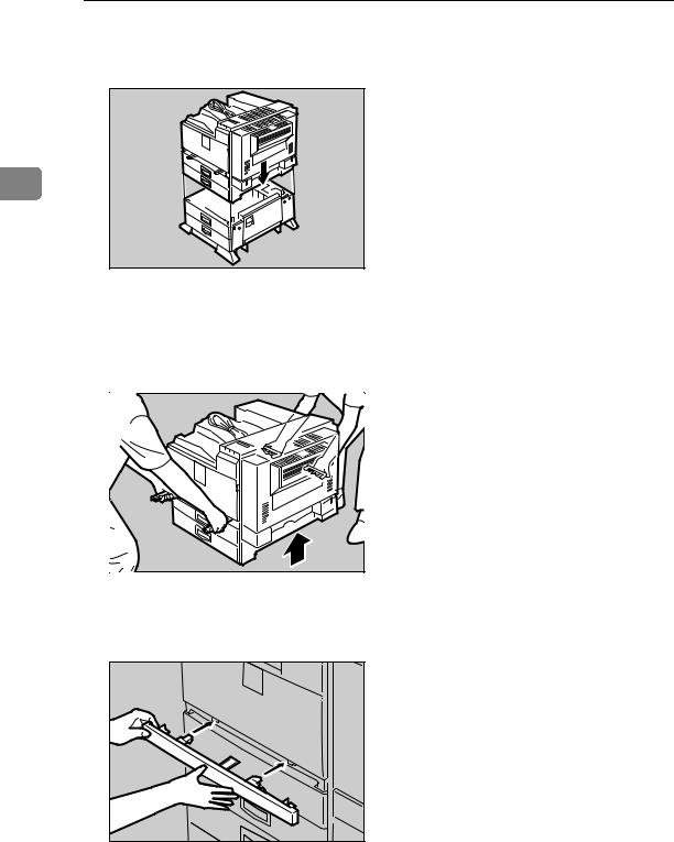
D Align the printer with the two upright pins on the paper feed unit and then lower the printer slowly.
2
AQV007S
•The printer should be held by least two people.
•When lifting the printer, pull out the grips from the front of the printer. One person should hold the grips on the front and another person should hold the grips on the rear.
AQV003S |
E Push the grips into the printer. Take out the cover inside Tray 2 and attach it between the paper tray and the front cover.
AQV001S |
12

Attaching Paper Feed Unit PB 3020
F Pull the second paper tray (Tray 2) until it stops. After that, lift it slightly, and then pull it out.
2
AQV732S
G Pull out the first paper tray (Tray 1) , and take the screwdriver (1) from the tray.
AQV222S
H Lock the Paper Bank and the printer with the screw.
AQV731S |
Be sure to return the screwdriver to the paper tray after using it.
13
Installing Options
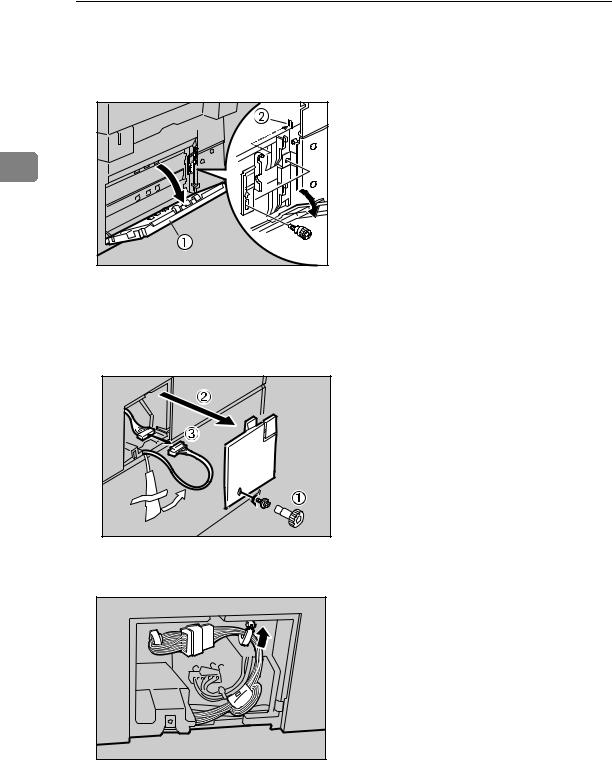
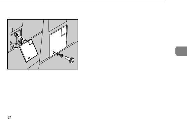
I Open the lower vertical paper feed cover on the right side of the paper feed unit (1). Hang the lock plate hook in the hole inside (2), and then fasten the plate with the knob screw using your fingers.
2 |
AQV042S |
J Close the lower vertical paper feed cover.
K Open the connector cover (2), remove the tape that holds the connector cable and attach the connector cables (3) as shown in the illustration.
AQV009S |
L Fasten the band as shown until it clicks to secure the cable.
AQV522S
14
Attaching Paper Feed Unit PB 3020
M Close the connector cover.
2
AQV010S

 Note
Note
Print a configuration page to confirm that the paper feed unit is properly installed.
If the paper feed unit is not installed properly, reinstall it following this procedure. If you cannot install it properly even after attempting reinstallation, contact your sales or service representative.

 Reference
For printing the configuration page, see “Printing the Test Page”, Quick Installation Guide.
For loading paper onto the paper tray, see p.71 “Loading Paper”.
When adjusting the printing position, see p.96 “Adjusting Tray Registration”.
15
Installing Options
Attaching User Account Enhance Unit Type E
RCAUTION:
•Do not touch the inside of the controller board compartment. Doing so may cause a malfunction or a burn.
2 Important
Before touching the User Account Enhance Unit, ground yourself by touching something metal to discharge any static electricity. Static electricity can damage User Account Enhance Unit.
Do not subject User Account Enhance Unit to physical shocks.
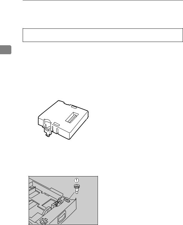
A Check the package contains the following:
User Account Enhance Unit Type E
AET080S
B Turn off the printer.
C Pull out the first paper tray (Tray 1) and take the screwdriver (1) from the tray. Each screw to be removed requires this screwdriver.
AQV222S
16

Attaching User Account Enhance Unit Type E
D Remove the screws as shown by turning them counterclockwise using the provided screwdriver.
2
AQV500S
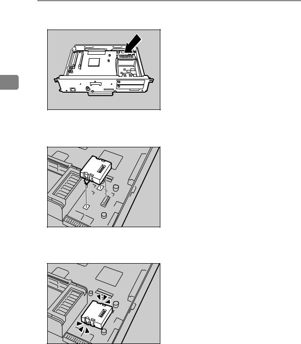
E Hold the part (1) of the controller board, and then slide it out completely.
AQV501S
F Place the controller board on a flat surface.
AQV516S |
17
Installing Options
G Be sure to install the User Account Enhance Unit as shown.
2 |
AQU012S |
H Align the notch of User Account Enhance Unit, and then insert it into the controller board, pressing it down until it clicks into place.
AQU013S |
I Make sure that User Account Enhance Unit is firmly connected to the controller board.
AQU014S |
18
Attaching User Account Enhance Unit Type E
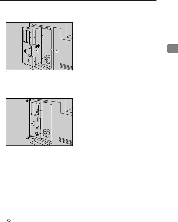
J Store the controller board (1) into the printer while gently pressing the cover (2).
2
AQV502S
Push in the controller board firmly to align the rails in the printer's compartment.
K Fasten all the screws which you removed in step D.
AQV503S
The printer may malfunction if the controller board is not properly installed.

 Note
Note
Be sure to return the screwdriver to the paper tray after using it.
After finishing installation, you can check whether the User Account Enhance Unit is properly installed: Print the configuration page from the [List/Test Print] menu. If it is installed properly, “Accounting Module” will appear for “Device Connection” on the configuration page.
If the User Account Enhance unit is not installed properly, reinstall it following this procedure. If you cannot install it properly even after attempting reinstallation, contact your sales or service representative.
Install the controller board carefully to prevent any malfunction.

 Reference
For printing the configuration page, see “Printing the Test Page”, Quick Installation Guide.
19
 Loading...