


 Loading...
hp StorageWorks
edge switch 2/16 service manual
Part Number: A7284-96002/AA-RS2JA-TE
First Edition (August 2002)
This manual describes the hp StorageWorks edge switch 2/16 and attached hp StorageWorks ha-fabric manager (HAFM) application. For service representatives, it describes diagnostic procedures, repair procedures, and the removal and replacement procedures for field-replaceable units (FRUs). An illustrated parts breakdown is included for all FRUs.
© Hewlett-Packard Company, 2002. All rights reserved.
Hewlett-Packard Company makes no warranty of any kind with regard to this material, including, but not limited to, the implied warranties of merchantability and fitness for a particular purpose. Hewlett-Packard shall not be liable for errors contained herein or for incidental or consequential damages in connection with the furnishing, performance, or use of this material.
This document contains proprietary information, which is protected by copyright. No part of this document may be photocopied, reproduced, or translated into another language without the prior written consent of Hewlett-Packard. The information contained in this document is subject to change without notice.
Microsoft, MS-DOS, and Windows are trademarks of Microsoft Corporation in the U.S. and/or other countries.
All other product names mentioned herein may be trademarks of their respective companies.
Hewlett-Packard Company shall not be liable for technical or editorial errors or omissions contained herein. The information is provided “as is” without warranty of any kind and is subject to change without notice. The warranties for Hewlett-Packard Company products are set forth in the express limited warranty statements accompanying such products. Nothing herein should be construed as constituting an additional warranty.
Printed in the U.S.A.
edge switch 2/16 service manual First Edition (August 2002)
Part Number: A7284-96002/AA-RS2JA-TE

Contents
About this Guide
Intended Audience . . . . . . . . . . . . . . . . . . . . . . . . . . . . . . . . . . . . . . . . . . . . . . . . . . . . . . xiii Related Documentation . . . . . . . . . . . . . . . . . . . . . . . . . . . . . . . . . . . . . . . . . . . . . . . . . . xiii Document Conventions . . . . . . . . . . . . . . . . . . . . . . . . . . . . . . . . . . . . . . . . . . . . . . . . . . xiv Symbols in Text . . . . . . . . . . . . . . . . . . . . . . . . . . . . . . . . . . . . . . . . . . . . . . . . . . . . . . . . xv Symbols on Equipment . . . . . . . . . . . . . . . . . . . . . . . . . . . . . . . . . . . . . . . . . . . . . . . . . . xv Rack Stability . . . . . . . . . . . . . . . . . . . . . . . . . . . . . . . . . . . . . . . . . . . . . . . . . . . . . . . . . . xvi Getting Help . . . . . . . . . . . . . . . . . . . . . . . . . . . . . . . . . . . . . . . . . . . . . . . . . . . . . . . . . . xvii
HP Technical Support . . . . . . . . . . . . . . . . . . . . . . . . . . . . . . . . . . . . . . . . . . . . . . . xvii HP Website . . . . . . . . . . . . . . . . . . . . . . . . . . . . . . . . . . . . . . . . . . . . . . . . . . . . . . . xvii HP Authorized Reseller . . . . . . . . . . . . . . . . . . . . . . . . . . . . . . . . . . . . . . . . . . . . . . . . . xvii
General Information
Switch Description . . . . . . . . . . . . . . . . . . . . . . . . . . . . . . . . . . . . . . . . . . . . . . . . . . . . . 1–1
Switch Management . . . . . . . . . . . . . . . . . . . . . . . . . . . . . . . . . . . . . . . . . . . . . . . . 1–3
Error-Detection, Reporting, and Serviceability Features . . . . . . . . . . . . . . . . . . . . 1–5
Zoning Feature. . . . . . . . . . . . . . . . . . . . . . . . . . . . . . . . . . . . . . . . . . . . . . . . . . . . . 1–7
Multi-Switch Fabrics . . . . . . . . . . . . . . . . . . . . . . . . . . . . . . . . . . . . . . . . . . . . . . . . 1–8
Switch Specifications . . . . . . . . . . . . . . . . . . . . . . . . . . . . . . . . . . . . . . . . . . . . . . . . . . . 1–9
Physical Characteristics . . . . . . . . . . . . . . . . . . . . . . . . . . . . . . . . . . . . . . . . . . 1–9
HAFM Server Description . . . . . . . . . . . . . . . . . . . . . . . . . . . . . . . . . . . . . . . . . . . . . . 1–11
HAFM Server Specifications. . . . . . . . . . . . . . . . . . . . . . . . . . . . . . . . . . . . . . . . . 1–12
Ethernet Hub . . . . . . . . . . . . . . . . . . . . . . . . . . . . . . . . . . . . . . . . . . . . . . . . . . . . . 1–13
Embedded Web Server Interface. . . . . . . . . . . . . . . . . . . . . . . . . . . . . . . . . . . . . . 1–13
Maintenance Approach . . . . . . . . . . . . . . . . . . . . . . . . . . . . . . . . . . . . . . . . . . . . . . . . 1–13
Remote Workstation Configurations . . . . . . . . . . . . . . . . . . . . . . . . . . . . . . . . . . . . . . 1–14
Minimum Remote Console Hardware Specifications . . . . . . . . . . . . . . . . . . . . . . 1–16
Field Replaceable Units . . . . . . . . . . . . . . . . . . . . . . . . . . . . . . . . . . . . . . . . . . . . . . . . 1–17
SFP Transceivers . . . . . . . . . . . . . . . . . . . . . . . . . . . . . . . . . . . . . . . . . . . . . . . . . . 1–19
Cooling Fans . . . . . . . . . . . . . . . . . . . . . . . . . . . . . . . . . . . . . . . . . . . . . . . . . . . . . 1–19
edge switch 2/16 installation guide |
iii |

Contents
Power Supplies. . . . . . . . . . . . . . . . . . . . . . . . . . . . . . . . . . . . . . . . . . . . . . . . . . . . 1–19
Connectors and Indicators . . . . . . . . . . . . . . . . . . . . . . . . . . . . . . . . . . . . . . . . . . . 1–19
Initial Machine Load Button . . . . . . . . . . . . . . . . . . . . . . . . . . . . . . . . . . . . . . . . . 1–20
Ethernet LAN Connector . . . . . . . . . . . . . . . . . . . . . . . . . . . . . . . . . . . . . . . . . . . . 1–20
Power and System Error LEDs . . . . . . . . . . . . . . . . . . . . . . . . . . . . . . . . . . . . . . . 1–20
FRU Status LEDs. . . . . . . . . . . . . . . . . . . . . . . . . . . . . . . . . . . . . . . . . . . . . . . . . . 1–21
Maintenance Port . . . . . . . . . . . . . . . . . . . . . . . . . . . . . . . . . . . . . . . . . . . . . . . . . . 1–21
Software Diagnostic Features . . . . . . . . . . . . . . . . . . . . . . . . . . . . . . . . . . . . . . . . . . . . 1–21
HAFM Diagnostics . . . . . . . . . . . . . . . . . . . . . . . . . . . . . . . . . . . . . . . . . . . . . . . . 1–22
HAFM Status Symbols . . . . . . . . . . . . . . . . . . . . . . . . . . . . . . . . . . . . . . . . . . 1–23
Hardware View Layout and Function . . . . . . . . . . . . . . . . . . . . . . . . . . . . . . . . . . 1–24
Menu Bar . . . . . . . . . . . . . . . . . . . . . . . . . . . . . . . . . . . . . . . . . . . . . . . . . . . . . 1–24
Product Manager Diagnostics . . . . . . . . . . . . . . . . . . . . . . . . . . . . . . . . . . . . . . . . 1–25
Hardware View . . . . . . . . . . . . . . . . . . . . . . . . . . . . . . . . . . . . . . . . . . . . . . . . 1–25
Status Table . . . . . . . . . . . . . . . . . . . . . . . . . . . . . . . . . . . . . . . . . . . . . . . . . . . 1–26
LED Emulation . . . . . . . . . . . . . . . . . . . . . . . . . . . . . . . . . . . . . . . . . . . . . . . . 1–27
Product Manager Status Symbols . . . . . . . . . . . . . . . . . . . . . . . . . . . . . . . . . . 1–27
View Tabs . . . . . . . . . . . . . . . . . . . . . . . . . . . . . . . . . . . . . . . . . . . . . . . . . . . . 1–28
View Panel. . . . . . . . . . . . . . . . . . . . . . . . . . . . . . . . . . . . . . . . . . . . . . . . . . . . 1–28
Status Bar. . . . . . . . . . . . . . . . . . . . . . . . . . . . . . . . . . . . . . . . . . . . . . . . . . . . . 1–35
Topology Tab . . . . . . . . . . . . . . . . . . . . . . . . . . . . . . . . . . . . . . . . . . . . . . . . . . . . . 1–37
Zone Set Tab . . . . . . . . . . . . . . . . . . . . . . . . . . . . . . . . . . . . . . . . . . . . . . . . . . . . . 1–38
HAFM Services Application . . . . . . . . . . . . . . . . . . . . . . . . . . . . . . . . . . . . . . . . . 1–38
Event Table . . . . . . . . . . . . . . . . . . . . . . . . . . . . . . . . . . . . . . . . . . . . . . . . . . . 1–39
Status Line . . . . . . . . . . . . . . . . . . . . . . . . . . . . . . . . . . . . . . . . . . . . . . . . . . . . 1–40
Embedded Web Server Diagnostics. . . . . . . . . . . . . . . . . . . . . . . . . . . . . . . . . . . . 1–41
SNMP Trap Message Support . . . . . . . . . . . . . . . . . . . . . . . . . . . . . . . . . . . . . . . . 1–42
E-Mail and Call-Home Support . . . . . . . . . . . . . . . . . . . . . . . . . . . . . . . . . . . . . . . 1–43
Tools and Test Equipment . . . . . . . . . . . . . . . . . . . . . . . . . . . . . . . . . . . . . . . . . . . . . . 1–43
Tools Supplied with the Switch . . . . . . . . . . . . . . . . . . . . . . . . . . . . . . . . . . . . . . . 1–43
Tools Supplied by Service Personnel. . . . . . . . . . . . . . . . . . . . . . . . . . . . . . . . . . . 1–44
Diagnostics
Maintenance Analysis Procedures . . . . . . . . . . . . . . . . . . . . . . . . . . . . . . . . . . . . . . . . . 2–1
Factory Defaults . . . . . . . . . . . . . . . . . . . . . . . . . . . . . . . . . . . . . . . . . . . . . . . . . . . . 2–1
Quick Start . . . . . . . . . . . . . . . . . . . . . . . . . . . . . . . . . . . . . . . . . . . . . . . . . . . . . . . . 2–1
MAP 0000: Start MAP . . . . . . . . . . . . . . . . . . . . . . . . . . . . . . . . . . . . . . . . . . . . . . . . . . 2–7
MAP 0100: Power Distribution Analysis . . . . . . . . . . . . . . . . . . . . . . . . . . . . . . . . . . . 2–26
iv |
edge switch 2/16 installation guide |

Contents
MAP 0200: POST, Reset, or IPL Failure Analysis . . . . . . . . . . . . . . . . . . . . . . . . . . . 2–32 MAP 0300: Console Application Problem Determination . . . . . . . . . . . . . . . . . . . . . 2–33 MAP 0400: Loss of Console Communication . . . . . . . . . . . . . . . . . . . . . . . . . . . . . . . 2–39 MAP 0500: Fan and CTP Failure Analysis . . . . . . . . . . . . . . . . . . . . . . . . . . . . . . . . . 2–58 MAP 0600: Port Failure and Link Incident Analysis. . . . . . . . . . . . . . . . . . . . . . . . . . 2–63 MAP 0700: Fabric, ISL, and Segmented Port Problem Determination. . . . . . . . . . . . 2–79 MAP 0800: Console PC Problem Determination . . . . . . . . . . . . . . . . . . . . . . . . . . . . 2–90
Repair Information
Factory Defaults . . . . . . . . . . . . . . . . . . . . . . . . . . . . . . . . . . . . . . . . . . . . . . . . . . . . . . . 3–2
Procedural Notes . . . . . . . . . . . . . . . . . . . . . . . . . . . . . . . . . . . . . . . . . . . . . . . . . . . . . . 3–2
Using Log Information. . . . . . . . . . . . . . . . . . . . . . . . . . . . . . . . . . . . . . . . . . . . . . . . . . 3–3
HAFM Audit Log . . . . . . . . . . . . . . . . . . . . . . . . . . . . . . . . . . . . . . . . . . . . . . . . . . 3–3
HAFM Event Log . . . . . . . . . . . . . . . . . . . . . . . . . . . . . . . . . . . . . . . . . . . . . . . . . . 3–3
Session Log . . . . . . . . . . . . . . . . . . . . . . . . . . . . . . . . . . . . . . . . . . . . . . . . . . . . . . . 3–4
Product Status Log. . . . . . . . . . . . . . . . . . . . . . . . . . . . . . . . . . . . . . . . . . . . . . . . . . 3–5
Fabric Log . . . . . . . . . . . . . . . . . . . . . . . . . . . . . . . . . . . . . . . . . . . . . . . . . . . . . . . . 3–5
Audit Log. . . . . . . . . . . . . . . . . . . . . . . . . . . . . . . . . . . . . . . . . . . . . . . . . . . . . . . . . 3–6
Event Log . . . . . . . . . . . . . . . . . . . . . . . . . . . . . . . . . . . . . . . . . . . . . . . . . . . . . . . . 3–6
Refresh the Event Log. . . . . . . . . . . . . . . . . . . . . . . . . . . . . . . . . . . . . . . . . . . . 3–7
Clear the Event Log . . . . . . . . . . . . . . . . . . . . . . . . . . . . . . . . . . . . . . . . . . . . . 3–7
Hardware Log . . . . . . . . . . . . . . . . . . . . . . . . . . . . . . . . . . . . . . . . . . . . . . . . . . . . . 3–7
Link Incident Log . . . . . . . . . . . . . . . . . . . . . . . . . . . . . . . . . . . . . . . . . . . . . . . . . . 3–9
Refresh the Link Incident Log . . . . . . . . . . . . . . . . . . . . . . . . . . . . . . . . . . . . 3–10
Clear the Link Incident Log . . . . . . . . . . . . . . . . . . . . . . . . . . . . . . . . . . . . . . 3–10
Threshold Alert Log . . . . . . . . . . . . . . . . . . . . . . . . . . . . . . . . . . . . . . . . . . . . . . . 3–10
Using Views . . . . . . . . . . . . . . . . . . . . . . . . . . . . . . . . . . . . . . . . . . . . . . . . . . . . . . . . . 3–12
Port List View . . . . . . . . . . . . . . . . . . . . . . . . . . . . . . . . . . . . . . . . . . . . . . . . . . . . 3–12
FRU List View. . . . . . . . . . . . . . . . . . . . . . . . . . . . . . . . . . . . . . . . . . . . . . . . . . . . 3–14
Node List View . . . . . . . . . . . . . . . . . . . . . . . . . . . . . . . . . . . . . . . . . . . . . . . . . . . 3–16
Performance View . . . . . . . . . . . . . . . . . . . . . . . . . . . . . . . . . . . . . . . . . . . . . . . . . 3–17
Zone Set View . . . . . . . . . . . . . . . . . . . . . . . . . . . . . . . . . . . . . . . . . . . . . . . . . . . . 3–17
Performing Port Diagnostics . . . . . . . . . . . . . . . . . . . . . . . . . . . . . . . . . . . . . . . . . . . . 3–19
Port LEDs . . . . . . . . . . . . . . . . . . . . . . . . . . . . . . . . . . . . . . . . . . . . . . . . . . . . . . . 3–19
Hardware View . . . . . . . . . . . . . . . . . . . . . . . . . . . . . . . . . . . . . . . . . . . . . . . . . . . 3–20
Performance View . . . . . . . . . . . . . . . . . . . . . . . . . . . . . . . . . . . . . . . . . . . . . . . . . 3–24
Perform Loopback Tests . . . . . . . . . . . . . . . . . . . . . . . . . . . . . . . . . . . . . . . . . . . . 3–26
Internal Loopback Test . . . . . . . . . . . . . . . . . . . . . . . . . . . . . . . . . . . . . . . . . . 3–26
edge switch 2/16 installation guide |
v |

Contents
External Loopback Test. . . . . . . . . . . . . . . . . . . . . . . . . . . . . . . . . . . . . . . . . . 3–28 Perform Channel Wrap Test. . . . . . . . . . . . . . . . . . . . . . . . . . . . . . . . . . . . . . . . . . 3–29 Swapping Ports . . . . . . . . . . . . . . . . . . . . . . . . . . . . . . . . . . . . . . . . . . . . . . . . . . . . . . . 3–30 Collecting Maintenance Data . . . . . . . . . . . . . . . . . . . . . . . . . . . . . . . . . . . . . . . . . . . . 3–31 Clean Fiber-Optic Components . . . . . . . . . . . . . . . . . . . . . . . . . . . . . . . . . . . . . . . . . . 3–33 Power-On Procedure. . . . . . . . . . . . . . . . . . . . . . . . . . . . . . . . . . . . . . . . . . . . . . . . . . . 3–34 Power-Off Procedure . . . . . . . . . . . . . . . . . . . . . . . . . . . . . . . . . . . . . . . . . . . . . . . . . . 3–35 Reset or IPL the Switch . . . . . . . . . . . . . . . . . . . . . . . . . . . . . . . . . . . . . . . . . . . . . . . . 3–35 Reset the Switch. . . . . . . . . . . . . . . . . . . . . . . . . . . . . . . . . . . . . . . . . . . . . . . . . . . 3–36 IPL the Switch . . . . . . . . . . . . . . . . . . . . . . . . . . . . . . . . . . . . . . . . . . . . . . . . . . . . 3–36 Set the Switch Online or Offline . . . . . . . . . . . . . . . . . . . . . . . . . . . . . . . . . . . . . . . . . 3–37 Set Online State . . . . . . . . . . . . . . . . . . . . . . . . . . . . . . . . . . . . . . . . . . . . . . . . . . . 3–37 Set Offline State . . . . . . . . . . . . . . . . . . . . . . . . . . . . . . . . . . . . . . . . . . . . . . . . . . . 3–38 Block and Unblock Ports . . . . . . . . . . . . . . . . . . . . . . . . . . . . . . . . . . . . . . . . . . . . . . . 3–39 Block a Port . . . . . . . . . . . . . . . . . . . . . . . . . . . . . . . . . . . . . . . . . . . . . . . . . . . . . . 3–39 Unblock a Port . . . . . . . . . . . . . . . . . . . . . . . . . . . . . . . . . . . . . . . . . . . . . . . . . . . . 3–39 Manage Firmware Versions . . . . . . . . . . . . . . . . . . . . . . . . . . . . . . . . . . . . . . . . . . . . . 3–40 Determine a Switch Firmware Version . . . . . . . . . . . . . . . . . . . . . . . . . . . . . . . . . 3–40 Add a Firmware Version . . . . . . . . . . . . . . . . . . . . . . . . . . . . . . . . . . . . . . . . . . . . 3–41 Modify a Firmware Version Description . . . . . . . . . . . . . . . . . . . . . . . . . . . . . . . . 3–44 Delete a Firmware Version . . . . . . . . . . . . . . . . . . . . . . . . . . . . . . . . . . . . . . . 3–45 Download a Firmware Version to a Switch . . . . . . . . . . . . . . . . . . . . . . . . . . . . . . 3–45 Manage Configuration Data . . . . . . . . . . . . . . . . . . . . . . . . . . . . . . . . . . . . . . . . . . . . . 3–48 Back Up the Configuration . . . . . . . . . . . . . . . . . . . . . . . . . . . . . . . . . . . . . . . . . . 3–48 Restore the Configuration . . . . . . . . . . . . . . . . . . . . . . . . . . . . . . . . . . . . . . . . . . . 3–49 Reset Configuration Data. . . . . . . . . . . . . . . . . . . . . . . . . . . . . . . . . . . . . . . . . . . . 3–50 Install or Upgrade Software . . . . . . . . . . . . . . . . . . . . . . . . . . . . . . . . . . . . . . . . . . . . . 3–51
FRU Removal and Replacement
Remove and Replace FRUs . . . . . . . . . . . . . . . . . . . . . . . . . . . . . . . . . . . . . . . . . . . . . . 4–1
FRUs . . . . . . . . . . . . . . . . . . . . . . . . . . . . . . . . . . . . . . . . . . . . . . . . . . . . . . . . . . . . 4–1
Procedural Notes . . . . . . . . . . . . . . . . . . . . . . . . . . . . . . . . . . . . . . . . . . . . . . . . . . . 4–2
RRP: SFP Transceiver . . . . . . . . . . . . . . . . . . . . . . . . . . . . . . . . . . . . . . . . . . . . . . . . . . 4–2
Removal . . . . . . . . . . . . . . . . . . . . . . . . . . . . . . . . . . . . . . . . . . . . . . . . . . . . . . . . . . 4–2
Replacement. . . . . . . . . . . . . . . . . . . . . . . . . . . . . . . . . . . . . . . . . . . . . . . . . . . . . . . 4–3
RRP: Power Supply . . . . . . . . . . . . . . . . . . . . . . . . . . . . . . . . . . . . . . . . . . . . . . . . . . . . 4–4
Removal . . . . . . . . . . . . . . . . . . . . . . . . . . . . . . . . . . . . . . . . . . . . . . . . . . . . . . . . . . 4–4
Replacement. . . . . . . . . . . . . . . . . . . . . . . . . . . . . . . . . . . . . . . . . . . . . . . . . . . . . . . 4–5
vi |
edge switch 2/16 installation guide |

Contents
RRP: Cooling Fan . . . . . . . . . . . . . . . . . . . . . . . . . . . . . . . . . . . . . . . . . . . . . . . . . . . . . 4–6
Removal. . . . . . . . . . . . . . . . . . . . . . . . . . . . . . . . . . . . . . . . . . . . . . . . . . . . . . . . . . 4–6
Replacement . . . . . . . . . . . . . . . . . . . . . . . . . . . . . . . . . . . . . . . . . . . . . . . . . . . . . . 4–7
RRP: CTP Card - Switch Replacement . . . . . . . . . . . . . . . . . . . . . . . . . . . . . . . . . . . . . 4–8
Replacing a Failed Switch . . . . . . . . . . . . . . . . . . . . . . . . . . . . . . . . . . . . . . . . . . . . 4–8
Illustrated Parts Breakdown
Front-Accessible FRUs . . . . . . . . . . . . . . . . . . . . . . . . . . . . . . . . . . . . . . . . . . . . . . . . . 5–1
Rear-Accessible FRUs . . . . . . . . . . . . . . . . . . . . . . . . . . . . . . . . . . . . . . . . . . . . . . . . . . 5–2
Miscellaneous Parts . . . . . . . . . . . . . . . . . . . . . . . . . . . . . . . . . . . . . . . . . . . . . . . . . . . . 5–3
Messages
HAFM Application Messages . . . . . . . . . . . . . . . . . . . . . . . . . . . . . . . . . . . . . . . . . . . . A–1
Edge-16 Switch Product Manager Messages. . . . . . . . . . . . . . . . . . . . . . . . . . . . . . . . A–18
Event Codes
System Events (000 through 199) . . . . . . . . . . . . . . . . . . . . . . . . . . . . . . . . . . . . . . . . . B–3 Power Supply Events (200 through 299) . . . . . . . . . . . . . . . . . . . . . . . . . . . . . . . . . . . B–11 Fan Module Events (300 through 399) . . . . . . . . . . . . . . . . . . . . . . . . . . . . . . . . . . . . B–15 CTP2 Card Events (400 through 499) . . . . . . . . . . . . . . . . . . . . . . . . . . . . . . . . . . . . . B–21 Port Events (500 through 599) . . . . . . . . . . . . . . . . . . . . . . . . . . . . . . . . . . . . . . . . . . . B–29 SBAR Events (600 through 699) . . . . . . . . . . . . . . . . . . . . . . . . . . . . . . . . . . . . . . . . . B–34 Thermal Events (800 through 899) . . . . . . . . . . . . . . . . . . . . . . . . . . . . . . . . . . . . . . . B–35
Glossary
Index
Figures
1–1 Switch, HAFM server, and Ethernet Hub . . . . . . . . . . . . . . . . . . . . . . . . . . . . . 1–2 1–2 Out-of-Band Product Management. . . . . . . . . . . . . . . . . . . . . . . . . . . . . . . . . . 1–4 1–3 Inband Product Management . . . . . . . . . . . . . . . . . . . . . . . . . . . . . . . . . . . . . . 1–5 1–4 HAFM Server . . . . . . . . . . . . . . . . . . . . . . . . . . . . . . . . . . . . . . . . . . . . . . . . . 1–12 1–5 12-Port Ethernet Hub . . . . . . . . . . . . . . . . . . . . . . . . . . . . . . . . . . . . . . . . . . . 1–13 1–6 Typical Network Configuration (One Ethernet Connection) . . . . . . . . . . . . . 1–15 1–7 Typical Network Configuration (Two Ethernet Connections) . . . . . . . . . . . . 1–16 1–8 Edge Switch 2/16 (front view) . . . . . . . . . . . . . . . . . . . . . . . . . . . . . . . . . . . . 1–18 1–9 Edge Switch 2/16 (rear view) . . . . . . . . . . . . . . . . . . . . . . . . . . . . . . . . . . . . . 1–18
edge switch 2/16 installation guide |
vii |
1–10 Product View . . . . . . . . . . . . . . . . . . . . . . . . . . . . . . . . . . . . . . . . . . . . . . . . . . 1–23 1–11 Hardware View . . . . . . . . . . . . . . . . . . . . . . . . . . . . . . . . . . . . . . . . . . . . . . . . 1–25 1–12 Hardware View . . . . . . . . . . . . . . . . . . . . . . . . . . . . . . . . . . . . . . . . . . . . . . . . 1–29 1–13 Port List View . . . . . . . . . . . . . . . . . . . . . . . . . . . . . . . . . . . . . . . . . . . . . . . . . 1–31 1–14 FRU List View. . . . . . . . . . . . . . . . . . . . . . . . . . . . . . . . . . . . . . . . . . . . . . . . . 1–32 1–15 Node List View . . . . . . . . . . . . . . . . . . . . . . . . . . . . . . . . . . . . . . . . . . . . . . . . 1–33 1–16 Performance View . . . . . . . . . . . . . . . . . . . . . . . . . . . . . . . . . . . . . . . . . . . . . . 1–34 1–17 Fabrics View - Topology Tab . . . . . . . . . . . . . . . . . . . . . . . . . . . . . . . . . . . . . 1–37 1–18 Fabrics View - Zone Sets Tab . . . . . . . . . . . . . . . . . . . . . . . . . . . . . . . . . . . . . 1–38 1–19 HAFM Services Window . . . . . . . . . . . . . . . . . . . . . . . . . . . . . . . . . . . . . . . . 1–39 1–20 Multi-mode and Single-mode Loopback Plugs . . . . . . . . . . . . . . . . . . . . . . . . 1–43 1–21 Fiber-Optic Protective Plug . . . . . . . . . . . . . . . . . . . . . . . . . . . . . . . . . . . . . . . 1–44 1–22 Null Modem Cable . . . . . . . . . . . . . . . . . . . . . . . . . . . . . . . . . . . . . . . . . . . . . 1–44 3–1 HAFM Event Log . . . . . . . . . . . . . . . . . . . . . . . . . . . . . . . . . . . . . . . . . . . . . . . 3–4 3–2 Product Status Log. . . . . . . . . . . . . . . . . . . . . . . . . . . . . . . . . . . . . . . . . . . . . . . 3–5 3–3 Switch Event Log . . . . . . . . . . . . . . . . . . . . . . . . . . . . . . . . . . . . . . . . . . . . . . . 3–6 3–4 Hardware Log . . . . . . . . . . . . . . . . . . . . . . . . . . . . . . . . . . . . . . . . . . . . . . . . . . 3–8 3–5 Link Incident Log . . . . . . . . . . . . . . . . . . . . . . . . . . . . . . . . . . . . . . . . . . . . . . . 3–9 3–6 Threshold Alert Log . . . . . . . . . . . . . . . . . . . . . . . . . . . . . . . . . . . . . . . . . . . . 3–11 3–7 Port List View . . . . . . . . . . . . . . . . . . . . . . . . . . . . . . . . . . . . . . . . . . . . . . . . . 3–13 3–8 FRU List View. . . . . . . . . . . . . . . . . . . . . . . . . . . . . . . . . . . . . . . . . . . . . . . . . 3–15 3–9 Node List View . . . . . . . . . . . . . . . . . . . . . . . . . . . . . . . . . . . . . . . . . . . . . . . . 3–16 3–10 Zone Sets View . . . . . . . . . . . . . . . . . . . . . . . . . . . . . . . . . . . . . . . . . . . . . . . . 3–18 3–11 Hardware View . . . . . . . . . . . . . . . . . . . . . . . . . . . . . . . . . . . . . . . . . . . . . . . . 3–20 3–12 Port Properties Dialog Box . . . . . . . . . . . . . . . . . . . . . . . . . . . . . . . . . . . . . . . 3–21 3–13 Performance View . . . . . . . . . . . . . . . . . . . . . . . . . . . . . . . . . . . . . . . . . . . . . . 3–24 3–14 Port Diagnostics Dialog Box . . . . . . . . . . . . . . . . . . . . . . . . . . . . . . . . . . . . . . 3–27 3–15 Channel Wrap On for Port n Dialog Box . . . . . . . . . . . . . . . . . . . . . . . . . . . . 3–30 3–16 Swap Ports Dialog Box . . . . . . . . . . . . . . . . . . . . . . . . . . . . . . . . . . . . . . . . . . 3–31 3–17 Save Data Collection Dialog Box . . . . . . . . . . . . . . . . . . . . . . . . . . . . . . . . . . 3–32 3–18 Data Collection Dialog Box . . . . . . . . . . . . . . . . . . . . . . . . . . . . . . . . . . . . . . 3–33 3–19 Clean Fiber-Optic Components . . . . . . . . . . . . . . . . . . . . . . . . . . . . . . . . . . . . 3–34 5–1 Front-Accessible FRUs . . . . . . . . . . . . . . . . . . . . . . . . . . . . . . . . . . . . . . . . . . . 5–1 5–2 Rear-Accessible FRUs. . . . . . . . . . . . . . . . . . . . . . . . . . . . . . . . . . . . . . . . . . . . 5–3

Contents
Tables
1–1 Status Symbols . . . . . . . . . . . . . . . . . . . . . . . . . . . . . . . . . . . . . . . . . . . . . . . . 1–24 1–2 Operating Status - Status Bar and Switch Status Table . . . . . . . . . . . . . . . . . 1–36 1–3 HAFM Services Status Symbols. . . . . . . . . . . . . . . . . . . . . . . . . . . . . . . . . . . 1–40 2–1 Factory-Set Defaults . . . . . . . . . . . . . . . . . . . . . . . . . . . . . . . . . . . . . . . . . . . . . 2–1 2–2 MAP Summary . . . . . . . . . . . . . . . . . . . . . . . . . . . . . . . . . . . . . . . . . . . . . . . . . 2–2 2–3 Event Codes versus Maintenance Action . . . . . . . . . . . . . . . . . . . . . . . . . . . . . 2–2 3–1 Factory-Set Defaults . . . . . . . . . . . . . . . . . . . . . . . . . . . . . . . . . . . . . . . . . . . . . 3–2 4–1 ESD Requirements . . . . . . . . . . . . . . . . . . . . . . . . . . . . . . . . . . . . . . . . . . . . . . 4–1 5–1 Front-Accessible FRU Parts List . . . . . . . . . . . . . . . . . . . . . . . . . . . . . . . . . . . 5–2 5–2 Rear-Accessible FRU Parts List . . . . . . . . . . . . . . . . . . . . . . . . . . . . . . . . . . . . 5–3 5–3 Miscellaneous Parts. . . . . . . . . . . . . . . . . . . . . . . . . . . . . . . . . . . . . . . . . . . . . . 5–3
edge switch 2/16 installation guide |
ix |
About this Guide
This manual describes the service procedures for the hp StorageWorks edge switch 2/16.
Intended Audience
This publication is intended for service personnel, and any individuals who monitor, configure, and repair the edge switch 2/16.
Related Documentation
In addition to this guide, HP provides corresponding information:
•hp StorageWorks product in a SAN environment - planning guide for director 2/64, edge switch 2/16, and edge switch 2/32, A6534-96025/AA-RS2DA-TE
•hp StorageWorks SNMP reference guide for director 2/64, edge switch 2/16, and edge switch 2/32, A6534-96026/AA-RQ7BB-TE
•hp StorageWorks CLI reference guide for director 2/64, edge switch 2/16, and edge switch 2/32, A6534-96027/AA-RQ7AB-TE
•hp StorageWorks edge switch 2/32 installation guide, A7283-96001/AA-RSTZA-TE
•hp StorageWorks edge switch 2/32 service manual, A7283-96002/AA-RS2GA-TE
•hp StorageWorks edge switch 2/32 product manager user guide, A7283-96003/AA-RS2HA-TE
•hp StorageWorks edge switch 2/32 release notes, A7283-96004/AV-RSU0A-TE
•hp StorageWorks edge switch 2/32 flexport upgrade instructions, A7290-96001/AA-RS33A-TE
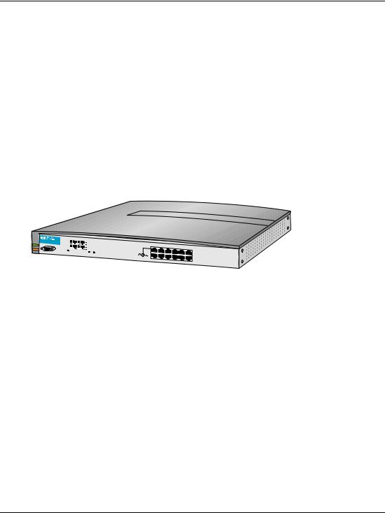
•hp StorageWorks edge switch 2/16 installation guide, A7284-96001/AA-RSU2A-TE
edge switch 2/16 service manual |
xiii |

About this Guide
•hp StorageWorks edge switch 2/16 product manager user guide, A7284-96003/AA-RS2KA-TE
•hp StorageWorks edge switch 2/16 release notes, A7284-96004/AV-RSU3A-TE
•hp StorageWorks edge switch rack mount installation instructions, A7283-96004/AA-RT4MA-TE
•hp StorageWorks HAFM server installation guide, A6582-96001/AA-RT4KA-TE
•hp StorageWorks ha-fabric manager user guide, A6534-96024/AA-RS2CA-TE
•hp StorageWorks ha-fabric manager release notes, A6575-96004/AV-RQZJC-TE
•hp StorageWorks SFP transceiver installation instructions, A6534-96030/AA-RSS3A-TE
Document Conventions
The conventions included in Table 1 apply.
Table 1: Document Conventions
Element |
Convention |
|
|
Cross-reference links |
Blue text: Figure 1 |
|
|
Key names, menu items, buttons, and |
Bold |
dialog box titles |
|
|
|
File names, application names, and text |
Italics |
emphasis |
|
|
|
User input, command names, system |
Monospace font |
responses (output and messages) |
COMMAND NAMES are uppercase |
|
|
|
unless they are case sensitive |
|
|
Variables |
Monospace, italic font |
|
|
Website addresses |
Sans serif font (http://thenew.hp.com) |
|
|
xiv |
edge switch 2/16 service manual |
About this Guide
Symbols in Text
These symbols may be found in the text of this manual. They have the following meanings.
WARNING: Text set off in this manner indicates that failure to follow directions in the warning could result in bodily harm or loss of life.
CAUTION: Text set off in this manner indicates that failure to follow directions could result in damage to equipment or data.
IMPORTANT: Text set off in this manner presents clarifying information or specific instructions.
NOTE: Text set off in this manner presents commentary, sidelights, or interesting points of information.
Symbols on Equipment
Any enclosed surface or area of the equipment marked with these symbols indicates the presence of electrical shock hazards. Enclosed area contains no operator serviceable parts.
WARNING: To reduce the risk of injury from electrical shock hazards, do not open this enclosure.
Any RJ-45 receptacle marked with these symbols indicates a network interface connection.
WARNING: To reduce the risk of electrical shock, fire, or damage to the equipment, do not plug telephone or telecommunications connectors into this receptacle.
edge switch 2/16 service manual |
xv |

About this Guide
Any surface or area of the equipment marked with these symbols indicates the presence of a hot surface or hot component. Contact with this surface could result in injury.
WARNING: To reduce the risk of injury from a hot component, allow the surface to cool before touching.
Power supplies or systems marked with these symbols indicate the presence of multiple sources of power.
WARNING: To reduce the risk of injury from electrical shock, remove all power cords to completely disconnect power from the power supplies and systems.
Any product or assembly marked with these symbols indicates that the component exceeds the recommended weight for one individual to handle safely.
WARNING: To reduce the risk of personal injury or damage to the equipment, observe local occupational health and safety requirements and guidelines for manually handling material.
Rack Stability
WARNING: To reduce the risk of personal injury or damage to the equipment, be sure that:
•The leveling jacks are extended to the floor.
•The full weight of the rack rests on the leveling jacks.
•In single rack installations, the stabilizing feet are attached to the rack.
•In multiple rack installations, the racks are coupled.
•Only one rack component is extended at any time. A rack may become unstable if more than one rack component is extended for any reason.
xvi |
edge switch 2/16 service manual |

About this Guide
Getting Help
If you still have a question after reading this manual, contact an HP authorized service provider or access our website: http://thenew.hp.com.
HP Technical Support
In North America, call technical support at 1-800-652-6672, available 24 hours a day, 7 days a week.
NOTE: For continuous quality improvement, calls may be recorded or monitored.
Outside North America, call technical support at the nearest location. Telephone numbers for worldwide technical support are listed on the HP website under support: http://thenew.hp.com/country/us/eng/support.html.
Be sure to have the following information available before calling:
•Technical support registration number (if applicable)
•Product serial numbers
•Product model names and numbers
•Applicable error messages
•Operating system type and revision level
•Detailed, specific questions
HP Website
The HP website has the latest information on this product, as well as the latest drivers. Access storage at: http://thenew.hp.com/country/us/eng/prodserv/storage.html. From this website, select the appropriate product or solution.
HP Authorized Reseller
For the name of your nearest HP Authorized Reseller:
•In the United States, call 1-800-345-1518
•In Canada, call 1-800-263-5868
•Elsewhere, see the HP website for locations and telephone numbers: http://thenew.hp.com.
edge switch 2/16 service manual |
xvii |

1
General Information
The hp StorageWorks edge switch 2/16 provides dynamic switched connections between Fibre Channel servers and devices in a storage area network (SAN) environment. SANs introduce the concept of server-to-device networking and multi-switch fabrics, eliminate requirements for dedicated connections, and enable the enterprise to become data centric.
A SAN provides speed, high capacity, and flexibility for the enterprise, and is primarily based upon Fibre Channel architecture. The switch implements Fibre Channel technology that provides a bandwidth of 2.125 gigabits per second, redundant switched data paths, a scalable number of active ports, and long transmission distances (up to 35 kilometers).
This chapter describes the switch and attached hp StorageWorks ha-fabric manager (HAFM) server. The chapter specifically discusses:
•Switch management, error-detection and reporting features, serviceability features, zoning, multi-switch fabrics, and specifications.
•The HAFM server and minimum hardware specifications.
•Remote workstation configurations and hardware specifications.
•Maintenance approach.
•Field-replaceable units (FRUs).
•Connectors and indicators.
•Software diagnostic features.
•Tools and test equipment.
Switch Description
The switch can be installed on a table or desk top, or mounted in an equipment cabinet or in any standard equipment rack.
edge switch 2/16 service manual |
1–1 |
General InformationI
Multiple switches and the HAFM server communicate on a local area network (LAN) through one or more 10/100Base-T Ethernet hubs. One or more 12-port Ethernet hubs are optional and can be ordered with the switch. Up to three hubs are daisy-chained as required to provide additional Ethernet connections as more switches (or other Hewlett Packard managed products) are installed on a customer network.
Figure 1–1 illustrates the switch, HAFM server, and Ethernet hub.
HAFM Server
HP Hub
Switch
Figure 1–1: Switch, HAFM server, and Ethernet Hub
The switch provides dynamic switched connections for servers and devices, supports mainframe and open-systems interconnection (OSI) computing environments, and provides data transmission and flow control between device node ports (N_Ports) as dictated by the Fibre Channel Physical and Signaling Interface (FC-PH 4.3). Through interswitch links (ISLs), the switch can connect additional switches to form a Fibre Channel multi-switch fabric.
The switch provides connectivity for devices manufactured by multiple original equipment manufacturers (OEMs). To determine if an OEM product can communicate through connections provided by the switch, or if communication restrictions apply, refer to the supporting publications for the product or contact your Hewlett Packard marketing representative
1–2 |
edge switch 2/16 service manual |

General InformationI
Switch Management
Out-of-band (non-Fibre Channel) management access to HP products is provided through an Ethernet LAN connection to a switch front panel. The following out-of-band management access methods are provided:
•Management through the HAFM application. The HAFM application includes the edge switch 2/16 Product Manager application. This GUI resides on the HAFM server and provides a single point of management for all directors and switches.
Operators at remote workstations can connect to the HAFM server through the local HAFM application and associated Product Manager applications to manage and monitor switches controlled by the HAFM server. A maximum of nine concurrent users (including a local user) can log in to the HAFM application.
•Management using simple network management protocol (SNMP). An SNMP agent is implemented through the HAFM application that allows administrators on SNMP management workstations to access product management information using any standard network management tool. Administrators can assign Internet Protocol (IP) addresses and corresponding community names for up to six SNMP workstations functioning as SNMP trap message recipients.
•Management through the Internet using the EWS interface installed on the switch. This interface supports configuration, statistics monitoring, and basic operation of the product, but does not offer all the capabilities of the corresponding Product Manager application. Administrators launch the web server interface from a remote PC by entering the product’s IP address as the Internet uniform resource locator (URL), then entering a user name and password at a login screen. The PC browser then becomes a management console.
•Management through a customer-supplied remote workstation communicating with the HAFM server through a corporate intranet.
•Management through the command line interface (CLI). The CLI allows you to access many HAFM and Product Manager applications while entering commands during a telnet session with the switch. The primary purpose of the CLI is to automate management of a large number of switches using scripts. The CLI is not an interactive interface; no checking is done for pre-existing conditions and no prompts display to guide users through tasks. Refer to the hp StorageWorks CLI reference guide for director 2/64, edge switch 2/16, and edge switch 2/32
(A6534-96027/AA-RQ7AB-TE).
Figure 1–2 illustrates an example of out-of-band product management. In the figure, the managed product is an edge switch 2/16.
edge switch 2/16 service manual |
1–3 |

General InformationI
2
10/100 Mbps
Corporate LAN
1 |
3 |
|
4
Internet
Connection
6
 5
5
SHR-2314d
1 |
SNMP management |
4 |
HAFM server |
|
workstation |
5 |
Web browser |
|
Remote user workstation |
||
2 |
6 |
Edge switch 2/16 |
|
|
|
3HP Ethernet hub
Figure 1–2: Out-of-Band Product Management
The following inband management access methods are provided as options:
•Management through the product’s open-system management server (OSMS) that communicates with an application client. The application resides on an open-systems interconnection (OSI) device attached to a switch port, and communicates using Fibre Channel common transport (FC-CT) protocol. Product operation, port connectivity, zoning, and fabric control are managed through a device-attached console.
•Management through the product’s Fibre Connection (FICON) management server (FMS) that communicates with the IBM System Automation for OS/390 (SA OS/390) operating system. The operating system resides on an IBM System/390 or zSeries 900 Parallel Enterprise Server attached to a director or switch port, and communicates through a FICON channel. Control of connectivity and statistical product monitoring are provided through a host-attached console.
1–4 |
edge switch 2/16 service manual |
General InformationI
Figure 1–3 on page 1-5 illustrates inband product management. In the figure, the managed product is an edge switch 2/16. The figure shows the following elements:
1
4 |
FICON |
2 |
|
||
|
Channel |
|
Fibre Channel
Connection
|
|
3 |
|
|
SHR-2364b |
1 S/390 or zSeries 900 parallel 3 |
Edge switch 2/16 |
|
Enterprise Server |
4 |
OSI server |
|
||
2Host-attached console
Figure 1–3: Inband Product Management
Error-Detection, Reporting, and Serviceability Features
The switch provides the following error-detection, reporting, and serviceability features:
•Light-emitting diodes (LEDs) on switch FRUs and adjacent to Fibre Channel ports that provide visual indicators of hardware status or malfunctions.
•System and threshold alerts, event logs, audit logs, link incident logs, threshold alert logs, and hardware logs that display switch, Ethernet link, and Fibre Channel link status at the HAFM server or on a remote workstation.
edge switch 2/16 service manual |
1–5 |

General InformationI
•Diagnostic software that performs power-on self-tests (POSTs) and port diagnostics (internal loopback, external loopback, and Fibre Channel (FC) wrap tests). The FC wrap test applies only when the switch is configured to operate in S/390 mode.
•Automatic notification of significant system events (to support personnel or administrators) through e-mail messages or the call-home feature.
•An internal modem in the HAFM server for HP call-home support
NOTE: For directors and switches installed in some legacy environments, call-home notification requires installation of HP Proactive Service software. This service is offered at no additional charge for subsystems covered under an on-site warranty or on-site storage hardware support contract. To register or order Proactive Service software, contact your HP customer service representative.
•An RS-232 maintenance port at the rear of the switch (port access is password protected) that enables installation or service personnel to change the switch’s internet protocol (IP) address, subnet mask, and gateway address; or to run diagnostics and isolate system problems through a local or remote terminal.
•Redundant FRUs; (small form factor pluggable (SFP)) optical transceivers, power supplies, and cooling fans that are removed or replaced without disrupting switch or Fibre Channel link operation.
•A modular design that enables quick removal and replacement of FRUs without tools or equipment.
•Concurrent port maintenance. SFPs and Fiber-optic cables are removed and attached to ports without interrupting other ports or switch operation.
•Beaconing to assist service personnel in locating a specific port or switch. When port beaconing is enabled, the amber LED associated with the port flashes. When unit beaconing is enabled, the system error indicator on the front panel flashes.
Beaconing does not affect port or switch operation.
•Data collection through the product manager application to help isolate system problems. The data includes a memory dump file and audit, hardware, and engineering logs.
•Status monitoring of redundant FRUs and alternate Fibre Channel data paths to ensure continued switch availability in case of failover. The HAFM application queries the status of each backup FRU daily. A backup FRU failure is indicated by an illuminated amber LED.
1–6 |
edge switch 2/16 service manual |

General InformationI
•Simple network management protocol (SNMP) management using the Fibre Alliance MIB that runs on the HAFM server. Up to 12 authorized management workstations can be configured through the HAFM application to receive unsolicited SNMP trap messages. The trap messages indicate operational state changes and failure conditions.
•SNMP management using the Fibre Channel Fabric Element MIB, transmission control protocol/internet protocol (TCP/IP) MIB-II definition (RFC 1213), and a product-specific MIB, all of which run on each switch. Up to 12 authorized management workstations can be configured through the product manager application to receive unsolicited SNMP trap messages. The trap messages indicate switch operational state changes and failure conditions.
NOTE: For more information about SNMP support provided by Hewlett Packard products, refer to the hp StorageWorks SNMP reference guide for director 2/64, edge switch 2/16, and edge switch 2/32 (A6534-96026/AA-RQ7BB-TE).
Zoning Feature
The switch supports a name server zoning feature that partitions attached devices into restricted-access groups called zones. Devices in the same zone can recognize and communicate with each other through switched port-to-port connections. Devices in separate zones cannot communicate with each other.
Zoning is configured by authorizing or restricting access to name server information associated with device N_Ports that attach to switch fabric ports (F_Ports). A zone member is specified by the port number to which a device is attached, or by the eight-byte (16-digit) worldwide name (WWN) assigned to the host bus adapter (HBA) or Fibre Channel interface installed in a device. A device can belong to multiple zones.
CAUTION: If zoning is implemented by port number, a change to the switch fiber-optic cable configuration disrupts zone operation and may incorrectly include or exclude a device from a zone.
If zoning is implemented by WWN, removal and replacement of a device HBA or Fibre Channel interface (thereby changing the device WWN) disrupts zone operation and may incorrectly include or exclude a device from a zone.
In Open Fabric mode, only zoning by WWN is supported. Zoning by port numbers is not.
Zones are grouped into zone sets. A zone set is a group of zones that is enabled (activated) or disabled across all switches in a multi-switch fabric. Only one zone set per fabric can be enabled at one time.
edge switch 2/16 service manual |
1–7 |

General InformationI
Multi-Switch Fabrics
A Fibre Channel topology that consists of one or more interconnected switches or switch elements is called a fabric. Operational software provides the ability to interconnect switches (through expansion port (E_Port) connections) to form a multi-switch fabric. The data transmission path through the fabric is typically determined by fabric elements and is user-transparent. Subject to zoning restrictions, devices attached to any interconnected switch can communicate with each other through the fabric.
Because a multi-switch fabric is typically complex, maintenance personnel should be aware that several factors can degrade fabric performance or cause connectivity failures. These factors include:
•Domain ID assignment - Each switch in a fabric is identified by a unique domain ID that ranges from 1 through 31. A domain ID of 0 is invalid. If two operational fabrics join, they determine if any domain ID conflicts exist between the fabrics. If one or more conflicts exist, the E_Ports that form the interswitch link (ISL) segment to prevent the fabrics from joining.
•Zoning - In a multi-switch fabric, zoning is configured on a fabric-wide basis, and any change to the zoning configuration is applied to all switches in the fabric. To ensure zoning is consistent across a fabric, the following rules are enforced when two fabrics (zoned or unzoned) join:
—Fabric A unzoned and Fabric B unzoned - The fabrics join successfully, and the resulting fabric remains unzoned.
—Fabric A zoned and Fabric B unzoned - The fabrics join successfully, and fabric B automatically inherits the zoning configuration from fabric A.
—Fabric A unzoned and Fabric B zoned - The fabrics join successfully, and fabric A automatically inherits the zoning configuration from fabric B.
—Fabric A zoned and Fabric B zoned - The fabrics join successfully only if the zone configurations can be merged. If the fabrics cannot join, the connecting ports segment and the fabrics remain independent.
Zone configurations for two fabrics are compatible (the zones can join) if the active zone set name is identical for each fabric, and if zones with the same name have identical elements.
•Port segmentation - When an ISL activates, the switches exchange operating parameters to determine if they are compatible and can join to form a single fabric. If incompatible, the connecting E_Port at each switch segments to prevent
1–8 |
edge switch 2/16 service manual |

General InformationI
the creation of a single fabric. A segmented link transmits only Class F traffic; the link does not transmit Class 2 or Class 3 traffic. The following conditions cause ports to segment:
—Incompatible operating parameters - either the resource allocation time-out value (R_A_TOV) or error-detect time-out value (E_D_TOV) is inconsistent between switches. To prevent port segmentation, the same E_D_TOV and R_A_TOV must be specified for each switch.
—Duplicate domain IDs - one or more domain ID conflicts are detected.
—Incompatible zoning configurations - zoning configurations for the switches are not compatible.
—Build fabric protocol error - a protocol error is detected during the process of forming the fabric.
—No principal switch - no switch in the fabric is capable of becoming the principal switch.
NOTE: At least one director or switch in a multi-switch fabric must be set to either principal or default, making it capable of becoming principal switch. If all directors and switches are set to never principal, all ISLs will segment (Reason code 05).
—Unresponsive switch - Each switch in a fabric periodically verifies operation of all attached switches. An ISL segments if the attached switch does not respond to a verification request.
—ELP retransmission failure timeout-a switch that exhibits a hardware failure or connectivity problem cannot transmit or receive Class F frames. The switch did not receive a response to multiple exchange link protocol (ELP) frames, did not receive a fabric login (FLOGI) frame, and cannot join an operational fabric.
Switch Specifications
This section lists the physical characteristics, storage and shipping environment, operating environment, and service clearances for the switch.
Physical Characteristics
Dimensions:
Height: 1.7 inches (4.3 centimeters)
Width: 17.5 inches (44.5 centimeters)
Depth: 25 inches (63.5 centimeters)
edge switch 2/16 service manual |
1–9 |

General InformationI
Weight: 26 pounds (11.8 kilograms)
Power Requirements:
Input voltage: 100 to 230 VAC
Input Frequency: 47 to 63 Hz
Plan for single phase or phase-to-phase connections and 5-ampere dedicated service
Airflow Clearance in Rack:
Sides: None
Top and Bottom: None
Front and Rear: 3.0 inches (7.6 centimeters)
Heat Dissipation:
410 BTU/Hr
Shock and Vibration Tolerance:
60 Gs for 10 milliseconds without nonrecoverable errors
Acoustical Noise:
70 dB “A” scale
Inclination:
10° maximum
Storage and Shipping Environment
Protective packaging must be provided to protect the switch under all shipping methods (domestic and international).
Shipping temperature:
-40° F to 140° F (-40° C to 60° C)
Storage temperature:
34° F to 140° F (1° C to 60° C)
Shipping relative humidity:
5% to 100%
Storage relative humidity:
1–10 |
edge switch 2/16 service manual |

General InformationI
5% to 80%
Maximum wet-bulb temperature:
84° F (29° C)
Altitude:
40,000 feet (12,192 meters)
Operating Environment
Temperature:
40° F to 104° F (4° C to 40° C)
Relative humidity:
8% to 80%
Maximum wet-bulb temperature:
81° F (27° C)
Altitude:
10,000 feet (3,048 meters)
HAFM Server Description
The HAFM server (Figure 1–1) is a notebook personal computer (PC) that provides a central point of control for up to 48 LAN-connected directors or edge switches.
edge switch 2/16 service manual |
1–11 |

General InformationI
Figure 1–4: HAFM Server
The server is mounted in a slide-out drawer in an HP-supplied equipment rack. The HAFM server or Internet access to the embedded web server interface is required to install, configure, and manage the switch.
Although a configured switch operates normally without HAFM server intervention, an attached server should operate at all times to monitor switch operation, log events and configuration changes, and report failures.
The HAFM server provides an auto-detecting 10/100 Mbps LAN connection, provided by an internal Ethernet adapter card. This LAN port attaches to the customer’s public intranet to allow access from remote user workstations. An optional Ethernet adapter card (not supplied by HP) can be installed in the personal computer memory card international association (PCMCIA) slot to provide a connection to a private LAN segment for dedicated switch communication.
HAFM Server Specifications
The following list summarizes hardware specifications for the HAFM server notebook platform. Current platforms may ship with more enhanced hardware, such as a faster processor, additional randomaccess memory (RAM), or a higher-capacity hard drive or removable disk drive.
•HP Omnibook 6200 PC with color monitor, keyboard, keyboard-mounted trackpad (mouse), and U. S. power cord.
•Intel® Pentium III™ processor with an 800 megahertz (MHz) or greater clock speed, running the Microsoft Windows 2000 operating system.
1–12 |
edge switch 2/16 service manual |
General InformationI
•Eighteen gigabyte (GB) or greater internal hard drive.
•160 megabyte (MB) or greater RAM.
•Removable DVD/CD-ROM drive.
•Removable 100 MB disk (Zip®) drive.
•56K internal modem.
•One internal 10/100 Mbps Ethernet adapter with RJ-45 connector (provides public LAN interface to switches and remote clients).
Ethernet Hub
The HAFM Server and managed switches connect through a rackmounted 10/100 Base-T Ethernet hub. Figure 1–5 illustrates the optional 12-port hub.
ProCurve 10/100 |
Hub 12 |
HP J3294A |
Power
Fault
1 |
2 |
3 |
4 |
5 |
6 |
7 |
8 |
9 |
10 |
11 |
12 |
Reset
Link
100
Link
100
Act |
Col |
|
Port 1 Only |
MDI-X |
MDI |
(out) |
(in) |
1 |
2X |
3X |
4X |
|
|
|
|
|
|
5X |
6X |
7X |
8X |
9X |
10X |
|
|
|
|
|
|
11X |
12X |
Figure 1–5: 12-Port Ethernet Hub
Embedded Web Server Interface
Administrators or operators with a browser-capable PC and an Internet connection can monitor and manage the switch through an embedded web server interface. The application provides a graphical user interface (GUI) similar to the product manager application, and supports switch configuration, statistics monitoring, and basic operation.
Maintenance Approach
Whenever possible, the maintenance approach instructs service personnel to perform fault isolation and repair procedures without degrading or interrupting operation of the switch, attached devices, or associated applications. Switch fault isolation begins when one or more of the following occur:
edge switch 2/16 service manual |
1–13 |

General InformationI
•System event information displays at the attached HAFM server, a remote workstation communicating with the HAFM server, or the embedded web server interface.
•LEDs on the switch front panel or FRUs illuminate to indicate a hardware malfunction.
•An unsolicited SNMP trap message is received at a management workstation, indicating an operational state change or failure.
•Notification of a significant system event is received at a designated support center through an e-mail message or the call-home feature.
System events can be related to a:
•Switch or HAFM server failure (hardware or software).
•Ethernet LAN communication failure between the switch and HAFM server
•Link failure between a port and attached device.
•ISL failure or segmentation of an E_port.
Fault isolation and service procedures vary depending on the system event information provided. Fault isolation and related service information is provided through maintenance analysis procedures (MAPs) documented in Chapter 3. MAPs consist of step-by-step procedures that prompt service personnel for information or describe a specific action to be performed. MAPs provide information to interpret system event information, isolate a switch failure to a single FRU, remove and replace the failed FRU, and verify switch operation. The fault isolation process normally begins with "MAP 0000: Start MAP" on page 2-7.
Ensure the correct switch is selected for service (if the HAFM server manages multiple switches or other Hewlett Packard products) by enabling unit beaconing at the failed switch. The amber system error LED on the switch front panel blinks when beaconing is enabled. Instructions to enable beaconing are incorporated into MAP steps.
Remote Workstation Configurations
Using a standard web browser, the HAFM and product manager applications can be downloaded and installed on remote user workstations that are LAN-attached to the HAFM server. Operators at these workstations can manage and monitor switches controlled by the HAFM server. A maximum of nine concurrent users (including a local user) can log in to the HAFM application.
1–14 |
edge switch 2/16 service manual |
Loading...