

Hoval TopGas Cascade 60, TopGas Cascade 80, TopGas Cascade 100, TopGas Cascade 120 Technical Information And Assembly Instructions
Technical Information and Assembly Manual
Output range 60 to 720 kW
4215256-00 - 11/16 Subject to modification
TopGas Cascade
Condensing Gas Boilers

2
TopGas Cascade 60 - 720 kW
4215256-00 - 11/16
Contents
Page No.
1. Important Information 4
1.1. Documentation 4
1.2. Guarantee 4
1.3. Other instructions 4
1.4. Safety instructions 4
1.5. Related Installation Documents 5
1.6. Transport and Storage 5
1.7. Installation. Location requirements 5
2. Technical Description 6
2.1. Technical Description 6
2.2. Cascade Product Codes 6
3. Technical Data 7
3.1. Technical data, TopGas
®
Cascade 60 7
3.2. Technical data, TopGas
®
Cascade 80 8
3.3. Technical data, TopGas
®
Cascade 100 9
3.4 Technical data, TopGas
®
Cascade 120 10
3.5. Technical Drawings, cascade in-line frame mounted 11
3.6. Technical Drawings, cascade back to back frame mounted 17
3.7. Technical Drawings, optional single and two boiler low loss headers 22
3.8. Technical Drawings, optional cascade low loss headers 23
3.9. Technical Drawings, optional cascade air and dirt separators 24
4. Installation requirements 25
4.1. Hydraulic Installation 25
4.2. Recommendations 25
4.3. Water Quality 25
4.4. Gas Connection 25
4.5. Flue Gas Connection, Chimney 26
4.6. Electrical Connections 26
4.7. Ventilation 26
4.8. Automatic Air Vent 26
4.9. Condensate Drainage 26
5. TopGas Cascade Assembly 27
5.1. Step 1: Build the frame (2-4 boiler inline, 3-4 boiler back to back) 27
5.1.1. Step 1: Build the frame (1 boiler inline, 2 boiler back to back) 29
5.2. Step 2: Mount the boilers 31
5.3. Step 3: Pipe the gas from the header to the boilers 32
5.4 Step4:Connectthenipplestotheowandreturnheaders 34
5.5. Step5:Connecttheboilertotheowandreturnheader(TopGas60and80) 35
5.5.1 Step5:Connecttheboilertotheowandreturnheader(TopGas100and120) 36
5.6. Step6:Connecttheblankinganges 37
5.7. Step 7: Fit the pre-formed insulation wrap 38
5.8. Step 8: Fitting the back boiler connections 38
6. Accessories - Hydraulics and Gas 40
6.1. Low loss header 40
6.2. Air and dirt separator 41

3
TopGas Cascade 60 - 720 kW
4215256-00 - 11/16
6.3. TopGas 60 single boiler low loss header 41
6.4. TopGas 80 single or two boiler low loss header 41
6.5. TopGas 100,120 single boiler low loss header 41
6.6. Boiler circulating pump, TopGas (60,80) 41
6.7. Pump insulation cover, TopGas (60,80) 41
6.8 Boiler circulating pump, TopGas (100,120) 41
6.9. Boilerowandreturnconnectionvalveset,TopGas(60,80) 42
6.10 Boilerowandreturnconnectionvalveset,TopGas(100,120) 42
6.11 Gas Filter 42
6.12 Liquid gas conversion kit 42
7. Accessories Controls 43
8. Accessories - Flues (Individual - concentric) 46
8.1. Connection C100/150 to 2xE100PP 46
8.2. 1000mm extension (including support bracket) 46
8.3. 500mm extension (including support bracket) 46
8.4. Vertical terminal (black) with cap 46
8.5. Vertical adapter with 2 sample points 46
8.6. Vertical adapter with condensing drain connection, siphon kit & 2 sample points 46
8.7. 45° elbow 46
8.8. 90° elbow 46
8.9. Support bracket 46
8.10. Leadpitchedroofashing 46
8.11. Aluminiumatroofashing 47
8.12. Wall terminal kit (for horizontal discharge) 47
8.13. Air inlet non-return damper for TopGas (60-120) only 47
9. Accessories - Flues (Individual - Plume kit) 48
9.1. Plume management kit 48
9.2. Plume 90° elbow 48
9.3. Plume 45° elbow 48
9.4. Plume extension 48
9.5. Plume nose piece 48
10. Typical Hydraulic Schematic 49
Hoval Service and Spares Contact details 50
4
TopGas Cascade 60 - 720 kW
4215256-00 - 11/16
1. Important Information
1.1. Documentation
Hoval gas boilers are only to be installed and placed in operation
by suitably qualied technicians; these instructions are therefore
intended to give a brief description of the Hoval TopGas Cascade
for the specialist covering the installation, commissioning, and
subsequent maintenance of these units. Other documents apply
in addition to these instructions. We accept no liability for any
damage caused by failure to observe these instructions.
The installation of boilers and their ancillary equipment is
normally carried out by the Heating Engineer, and for the purpose
of this manual he / she is regarded as the installer, and, as such,
it is his / her responsibility to ensure that he / she has read and
understood the contents of this manual before installing the
boiler.
1.2. Guarantee
Important Note: Proper functionality is only guaranteed if the
installation and operating instructions are observed and the boiler
is regularly maintained. The installation should be in accordance
with current I.E.E. Regulations, relevant British & European
Standards and Codes of Practice, Building Regulations and Local
Authority Bylaws.
Troubleshooting and damage repair caused by contaminated
operating media (gas, water, combustion air), unsuitable
chemical additives to the heating water, incorrect handling, faulty
installation, inadmissible modications and damage due to the
exercising of force are not covered by our warranty; the same
applies to corrosion through halogen compounds, e.g. from spray
cans, paints, adhesives, solvents and cleaning agents. Hoval
gas boilers are only to be installed by competent and qualied
persons. No modications are to be made to the boilers.
1.3. Other instructions
Depending on the model, any further instructions are enclosed
with the individually packed components. For any adjustments
and additional accessories please refer to the relevant Technical
Information Installation Instructions for the individual Hoval
TopGas boilers and any relevant installation Standards and
Regulations.
1.4. Safety instructions
Installation and maintenance of the boiler must only be
performed by a competent person with valid accreditation from
the Health and Safety Executive in accordance with the “Gas
Safety (Installation and Use) Regulations 1998”. The existing
regulations, rules and guidelines must be observed when doing
so. The competent person is also responsible for inspection,
maintenance and repairs to the boiler, and alterations to the gas
volume setting.
There is a risk of injury or death to the user or others, or of
damage to the product and other property, in the event of
improper use or use for which it is not intended. The product is
intended as a heat generator for closed hot water/central heating
installations and for hot water generation.
The system may only be placed in operation when all relevant
standards and safety regulations have been complied with. The
following conditions must be satised:
• Safety valve installed (closed system)
• Power supplies connected and tested
• Controls system commissioned
• System lled with water and suitably treated
• Expansion vessel connected and charged
• Boilers connected to an appropriate ue or chimney
• Burner parameters are set correctly
When maintaining working on individual appliances or the
TopGas cascade assembly;
• Allow the gas boilers to cool
• Switch off the boilers and isolate from the electrical supply
• Shut off the gas isolating valve to either the individual
appliance or the cascade gas header
• Close the isolation valves of the appliance (heating ow and
return)
• Replace all removed covers and cladding on completion of
the repair / maintenance work
• Do not exceed the maximum operating pressure and
temperature of the gas boiler (see identication plate)
What to do in an emergency if you smell gas
Installation errors, damage, tampering, unauthorised installation
sites or similar can cause gas to escape and result in a risk of
poisoning and explosion. If there is a smell of gas in the building,
proceed as follows:
• Avoid rooms that smell of gas
• If possible, open doors and windows fully and ensure
adequate ventilation
• Do not use naked ames (e.g. lighters, matches)
• Do not smoke
• Do not use any electrical switches, mains plugs, doorbells,
telephones
• Close the gas meter isolator device or the main isolator
• If possible, close the gas isolator cock in the gas supply
• Leave the building
• If you can actually hear gas leaking, leave the building
immediately and ensure that others do not enter the building
• Alert the re brigade and police when you are outside the
building
• Notify the gas supply company or National Grid Transco
0800 111 999 by telephone from outside the building!

5
TopGas Cascade 60 - 720 kW
4215256-00 - 11/16
1.5. Related Installation Documents
To ensure the safe installation and continued satisfactory
operation of your appliance, all works shall be carried out by a
competent installer fully conversant with the required current and
up to date, acts, standards, laws and regulations relevant for this
range of equipment at the time of installation. Installers shall carry
out a full site risk assessment and put into place all necessary
steps and procedures to comply with the Health and Safety at
Work Act and ensure safety of themselves and others with regard
to manual handling and working at height requirements.
Attention shall be paid to (but not restricted to) the following:
• Gas Safety (Installation and Use) regulations
• Non Domestic Heating, Cooling and Ventilation Compliance
Guide
• All current Building Regulations for England and Wales
(Includes Approved Codes of Practice and Approved
Documents for building regulations e.g. L1, L2A, L2B, L8)
• The Building Standards, Scotland, and any requirements
determined by the local authorities within
• BS 7671 Requirements for electrical installations. IEE Wiring
Regulations
• The Electricity at Work Regulations
• The Clean Air Act 1993, 1968 1993 and the 3rd Edition
of the Chimney Height memorandum 1981. (installations
exceeding 150 kW)
• The Water supply (water ttings) regulations 1999
• BS 5440-1 Flueing and ventilation for gas appliances
• BS 5854 Code of practice for ues and ue structures in
buildings
• BS EN 12828 Design of water-based heating systems
• BS 6644 Specication for the installation of gas red hot
water boilers with rated inputs between 70 kW (net) and
1.8 MW (net) (2nd and 3rd family gases)
• BS 6700 Specication for the design, installation, testing
and maintenance of services supplying water for domestic
use within buildings and their curtilages
• BS 6880 Code of practice for low temperature heating
systems with outputs greater than 45 kW:
Part 1 Fundamental and design considerations
Part 2 Selection of equipment
Part 3 Installation, commissioning and maintenance
• BS 6981 Installation of low pressure gas pipework of up to
35mm in domestic premises
• BS 4814 Specication for: Expansion vessels using an
internal diaphragm, for sealed hot water and heating
systems
• BS 7074 Application, selection and installation of expansion
vessels and ancillary equipment for sealed water systems
Part 1 Code of practice for domestic heating and hot
water
Part 2 Code of practice for low and medium
temperature hot water systems
• BS 7593 Code of practice for treatment of water in domestic
hot water central heating systems
• BS EN 13831 Closed expansion vessels with built in
diaphragm
• BS EN 14336 Heating systems in buildings. Installation and
commissioning of water based heating systems
• Directive VDI 2035 Prevention of damage in water heating
systems due to scale formation
• Institute of Gas Engineers Publications:
IGE/UP/1 (Edition 2) Strength testing, tightness testing
and direct purging of industrial and commercial gas
installations
IGE/UP/1A (Edition 2) Strength testing, tightness
testing and direct purging of small, low pressure
industrial and commercial natural gas installations
IGE/UP/1B (Edition 2) Tightness testing and direct
purging of small natural gas installations
IGE/UP/2 (Edition 2) Installation pipework on industrial
and commercial premises
IGE/UP/7 (Edition 2) Gas in timber and light steel
framed buildings
IGE/UP/10 Installation of gas appliances in industrial
and commercial premises. Part 1 Flued appliances
1.6. Transport and Storage
Please remove the packing materials and examine the
consignment for correctness, completeness and possible
transport damage. The equipment is to be transported and stored
only in its original packing. Interim storage of Hoval gas boilers
should only to take place in weather protected rooms and only in
the original packing. The ambient conditions for storage must be
within the following limits:
• Air temperature: -10°C - 50°C
• Air humidity: 50 - 85% relative humidity
• No condensation
1.7. Installation. Location requirements
The installation site of the boiler cascade should allow proper
connection of the ue duct work to all the boilers in the cascade.
In addition, there should be adequate room for maintenance and
air circulation around the cascade of boilers.
The boiler cascade must be set up in a separate installation
room.
A oor standing boiler cascade must be installed on a at, or level
re proof oor.
All boilers must have a minimum clearance of 500mm at the front
for preventative maintenance and commissioning work to be
carried out.

6
TopGas Cascade 60 - 720 kW
4215256-00 - 11/16
2. Technical Description
2.2. Cascade Product Codes
In-line frame mounted (not including optional low loss header or air/dirt separator)
Back to back frame mounted (not including low loss header or air/dirt separator)
Boiler Model No of boilers: One Two Three Four Five Six
TopGas 60 - 7015844 7015845 7015846 7015847 7015848
TopGas 80 - 7015824 7015823 7015822 7015821 7015820
TopGas 100 - 7015801 7015800 7015802 7015816 7015817
TopGas 120 - 7015859 7015828 7015827 7015826 7015825
2.1. Technical Description
The Hoval TopGas Cascade allows a number of individual Hoval
TopGas boilers to be mounted into a common arrangement.
A cascade of one to six TopGas (60), (80), (100) or (120) boilers
can be arranged in-line on a free standing frame. As an alternative
a cascade of two to six boilers can be arranged back to back on a
free standing frame.
Each individual Hoval TopGas boiler is a gas red appliance
suitable and approved as a heat producer for hot water heating
systems with a maximum ow temperature of 85°C and a
maximum operating pressure of 2.5 bar.
TopGas boilers are suitable for operation with either Natural Gas
or LPG.
Each boiler has an Aluminium Alloy integrated heat exchanger
complete with integral down ring pre-mix burner and is capable
of full condensing operation. The combustion air is drawn into the
boiler via the burner fan through openings in the top casing of each
boiler. This is directly from the plant room or via an air/ue gas con-
centric chimney arrangement allowing the boiler to be operated in
a room sealed (or room air independent) manner. The combustion
air is mixed with an incoming gas supply to match the individual
boiler output and combustion is completed across a high tempera-
ture stainless steel mesh adjacent to the heat exchanger. The hot
gases are forced through the heat exchanger to cool and deliver
their energy to the heating system and then discharged via the
ue. If the gases are cooled below their dew point condensation
will occur on the boiler surfaces.
Each TopGas boiler within the cascade is supplied with exible
ow and return hydraulic connections including ttings; a valve set
incorporating isolation valves, safety valve, non return valve, and
a drain valve; an A-rated circulating pump; and a gas connection
kit including an isolation valve, 28mm TracPipe and necessary t-
tings. A condensate trap is supplied with each boiler to be tted
and piped to drain by the installer.
A pipework header set is supplied with each cascade to allow all
the individual TopGas boilers to be connected together to create
the cascade. The LTHW and gas header size will vary depend-
ing on the cascade type. An insulation wrap is tted to the LTHW
header pipework.
When assembled the TopGas cascade boilers can be individually
controlled via an external building management system or can be
sequenced by the optional heating controller set TopTronic
®
E ZE1
into the master boiler with an additional TopTronic®E ZE3
module tted into all the other boilers in the cascade. A wired con-
nection must be tted between each boiler and a common ow
sensor tted into the pipework to allow control via the boiler(s).
The cascade of boilers are connected to LTHW and gas headers
forming a primary circuit via an optional low loss header or air/dirt
separator.
Each cascade is designed to operate with a ∆T of 20°C on the
primary circuit. When the optional low loss header or air/dirt sepa-
rator the secondary sized can operate with either an 11 or 20°C ∆T.
Each boiler in the cascade requires a suitable ue connection to
discharge products of combustion.
Note that the boilers require a minimum working pressure of 1 bar
and therefore the system pressure must be in line with this and
must encompass the required volume of expansion.
Each cascade is made up of individual boilers each of the same
size. It is NOT possible to arrange a cascade with different size
TopGas boilers. Please see the cascade options listed below.
For further information on the TopGas boiler please refer to the
Technical Information and Installation Instructions, document No.
4214783.
Boiler Model No of boilers: One Two Three Four Five Six
TopGas 60 7015818 7015839 7015840 7015841 7015842 7015843
TopGas 80 7015865 7015864 7015863 7015862 7015861 7015860
TopGas 100 7015799 7015773 7015812 7015813 7015814 7015815
TopGas 120 7015871 7015870 7015869 7015868 7015867 7015866

7
TopGas Cascade 60 - 720 kW
4215256-00 - 11/16
3.1. Technical data, TopGas® Cascade 60
Number of TopGas Boilers in Cascade Two Three Four Five Six
Nominal output at 80/60°C with Natural Gas kW 113.2 169.8 226.4 283.0 339.6
Nominal output at 40/30°C with Natural Gas kW 124.0 186.0 248.0 310.0 372.0
Nominal output at 80/60°C with LPG kW 113.2 169.8 226.4 283.0 339.6
Nominal output at 40/30°C with LPG kW 122.2 183.3 244.4 305.5 366.6
Nominal load with Natural Gas kW 115.4 173.1 230.8 288.5 346.2
Nominal load with Propane kW 115.4 173.1 230.8 288.5 346.2
Operating pressure, minimum/maximum bar 4 / 1 4 / 1 4 / 1 4 / 1 4 / 1
Operating temperature, maximum °C 85 85 85 85 85
Boiler water content litres 10.8 16.2 21.6 27.0 32.4
Boiler weight (dry, excluding frame and headers) kg 198 297 396 495 594
Frame, header and xings weight (inline) kg 259 459 518 718 777
Frame, header and xings weight (back to back) kg 248 301 317 517 565
Boiler full load efciency @ 80/60°C (nCV basis/ gCV basis) % 99.4/89.6 99.4/89.6 99.4/89.6 99.4/89.6 99.4/89.6
Boiler part load efciency @ 40/30°C (nCV basis/ gCV basis) % 110.4/99.5 110.4/99.5 110.4/99.5 110.4/99.5 110.4/99.5
UK Part L Seasonal efciency % 97.6 97.6 97.6 97.6 97.6
Standing losses at 70°C W 210 315 420 525 630
NO
X
emissions (dry and stoichoimetric) mg/kWh 27 27 27 27 27
Natural Gas pressure, minimum/maximum mbar 17.4 - 50 17.4 - 50 17.4 - 50 17.4 - 50 17.4 - 50
LPG pressure, minimum/maximum mbar 37 - 50 37 - 50 37 - 50 37 - 50 37 - 50
Gas consumption (corrected 0°C, 1013mbar)
Natural Gas E (HU 9.97kWh/m3) m3/h 13.6 20.19 26.92 33.65 40.38
Propane (HU 25.9 kWh/m3) m3/h 4.4 6.6 8.8 11 13.2
Operating voltage
(1)
V/Hz 230/50 230/50 230/50 230/50 230/50
Control voltage V/Hz 24/50 24/50 24/50 24/50 24/50
Type of protection IP 20 20 20 20 20
Condensate quantity (40/30°C Natural Gas) l/h 10.8 16.2 21.6 27.0 32.4
Condensate pH value 4-6 4-6 4-6 4-6 4-6
Flue gas mass ow kg/h 190.2 285.3 380.4 475.5 570.6
Flue gas temperature 80/60°C °C 65.6 65.6 65.6 65.6 65.6
Flue gas temperature 50/30°C °C 44.8 44.8 44.8 44.8 44.8
(1) Each boiler in the cascade requires a 230Vac, 10amp power supply
3. Technical data

8
TopGas Cascade 60 - 720 kW
4215256-00 - 11/16
3.2. Technical data, TopGas® Cascade 80
Number of TopGas Boilers in Cascade Two Three Four Five Six
Nominal output at 80/60°C with Natural Gas kW 147.4 221.1 294.8 368.5 442.2
Nominal output at 40/30°C with Natural Gas kW 162.0 243.0 324.0 405.0 486.0
Nominal output at 80/60°C with LPG kW 147.4 221.1 294.8 368.5 442.2
Nominal output at 40/30°C with LPG kW 159.8 239.7 319.6 399.5 479.4
Nominal load with Natural Gas kW 150.8 226.2 301.6 377.0 452.4
Nominal load with Propane kW 148.8 223.2 297.6 372.0 446.4
Operating pressure, minimum/maximum bar 4 / 1 4 / 1 4 / 1 4 / 1 4 / 1
Operating temperature, maximum °C 85 85 85 85 85
Boiler water content litres 10.8 16.2 21.6 27.0 32.4
Boiler weight (dry, excluding frame and headers) kg 198 297 396 495 594
Frame, header and xings weight (inline) kg 259 459 518 718 777
Frame, header and xings weight (back to back) kg 248 301 317 517 565
Boiler full load efciency @ 80/60°C (nCV basis/ gCV basis) % 98.8/89.0 98.8/89.0 98.8/89.0 98.8/89.0 98.8/89.0
Boiler part load efciency @ 40/30°C (nCV basis/ gCV basis) % 110.8/99.9 110.8/99.9 110.8/99.9 110.8/99.9 110.8/99.9
UK Part L Seasonal efciency % 97.8 97.8 97.8 97.8 97.8
Standing losses at 70°C W 210 315 420 525 630
NOX emissions (dry and stoichoimetric) mg/kWh 28 28 28 28 28
Natural Gas pressure, minimum/maximum mbar 17.4 - 50 17.4 - 50 17.4 - 50 17.4 - 50 17.4 - 50
LPG pressure, minimum/maximum mbar 37 - 50 37 - 50 37 - 50 37 - 50 37 - 50
Gas consumption (corrected 0°C, 1013mbar)
Natural Gas E (HU 9.97kWh/m3) m3/h 15 22.5 30 37.5 45
Propane (HU 25.9 kWh/m3) m3/h 5.76 8.64 11.52 14.4 17.28
Operating voltage
(1)
V/Hz 230/50 230/50 230/50 230/50 230/50
Control voltage V/Hz 24/50 24/50 24/50 24/50 24/50
Type of protection IP 20 20 20 20 20
Condensate quantity (40/30°C Natural Gas) l/h 14.2 21.3 28.4 35.5 42.6
Condensate pH value 4-6 4-6 4-6 4-6 4-6
Flue gas mass ow kg/h 249 373.3 498 622.5 747
Flue gas temperature 80/60°C °C 74.4 74.4 74.4 74.4 74.4
Flue gas temperature 40/30°C °C 52 52 52 52 52
(1) Each boiler in the cascade requires a 230Vac, 10amp power supply

9
TopGas Cascade 60 - 720 kW
4215256-00 - 11/16
3.3. Technical data, TopGas® Cascade 100
Number of TopGas Boilers in Cascade Two Three Four Five Six
Nominal output at 80/60°C with Natural Gas kW 180.8 271.2 361.6 452 542.4
Nominal output at 40/30°C with Natural Gas kW 200 300 400 500 600
Nominal output at 80/60°C with LPG kW 180.8 271.2 361.6 452 542.4
Nominal output at 40/30°C with LPG kW 200 300 400 500 600
Nominal load with Natural Gas kW 186 279 372 465 558
Nominal load with Propane kW 186 279 372 465 558
Operating pressure, minimum/maximum bar 4 / 1 4 / 1 4 / 1 4 / 1 4 / 1
Operating temperature, maximum °C 85 85 85 85 85
Boiler water content litres 14 21 28 35 42
Boiler weight (dry, excluding frame and headers) kg 232 348 464 580 696
Frame, header and xings weight (inline) kg 293 505 586 798 879
Frame, header and xings weight (back to back) kg 272 347 367 579 639
Boiler full load efciency @ 80/60°C (nCV basis/ gCV basis) % 98.3/88.6 98.3/88.6 98.3/88.6 98.3/88.6 98.3/88.6
Boiler part load efciency @ 40/30°C (nCV basis/ gCV basis) % 110.9/99.9 110.9/99.9 110.9/99.9 110.9/99.9 110.9/99.9
UK Part L Seasonal efciency % 97.8 97.8 97.8 97.8 97.8
Standing losses at 70°C W 230 345 460 575 690
NOX emissions (dry and stoichoimetric) mg/kWh 26 26 26 26 26
Natural Gas pressure, minimum/maximum mbar 17.4 - 50 17.4 - 50 17.4 - 50 17.4 - 50 17.4 - 50
LPG pressure, minimum/maximum mbar 37 - 50 37 - 50 37 - 50 37 - 50 37 - 50
Gas consumption (corrected 0°C, 1013mbar)
Natural Gas E (HU 9.97kWh/m3) m3/h 18.64 27.96 37.28 46.6 55.92
Propane (HU 25.9 kWh/m3) m3/h 7.18 10.77 14.36 17.95 21.54
Operating voltage
(1)
V/Hz 230/50 230/50 230/50 230/50 230/50
Control voltage V/Hz 24/50 24/50 24/50 24/50 24/50
Type of protection IP 20 20 20 20 20
Condensate quantity (40/30°C Natural Gas) l/h 17.8 26.7 35.6 44.5 53.4
Condensate pH value 4-6 4-6 4-6 4-6 4-6
Flue gas mass ow kg/h 310 465 620 775 930
Flue gas temperature 80/60°C °C 69 69 69 69 69
Flue gas temperature 40/30°C °C 48 48 48 48 48
(1) Each boiler in the cascade requires a 230Vac, 10amp power supply

10
TopGas Cascade 60 - 720 kW
4215256-00 - 11/16
3.4. Technical data, TopGas® Cascade 120
Number of TopGas Boilers in Cascade Two Three Four Five Six
Nominal output at 80/60°C with Natural Gas kW 215.2 322.8 430.4 538 645.6
Nominal output at 40/30°C with Natural Gas kW 240 360 480 600 720
Nominal output at 80/60°C with LPG kW 215.2 322.8 430.4 538 645.6
Nominal output at 40/30°C with LPG kW 240 360 480 600 720
Nominal load with Natural Gas kW 223 334.5 446 557.5 669
Nominal load with Propane kW 223 334.5 446 557.5 669
Operating pressure, minimum/maximum bar 4 / 1 4 / 1 4 / 1 4 / 1 4 / 1
Operating temperature, maximum °C 85 85 85 85 85
Boiler water content litres 14 21 28 35 42
Boiler weight (dry, excluding frame and headers) kg 232 348 464 580 696
Frame, header and xings weight (inline) kg 293 505 586 798 879
Frame, header and xings weight (back to back) kg 272 347 367 579 639
Boiler full load efciency @ 80/60°C (nCV basis/ gCV basis) % 97.7/88.0 97.7/88.0 97.7/88.0 97.7/88.0 97.7/88.0
Boiler part load efciency @ 40/30°C (nCV basis/ gCV basis) % 109.0/98.2 109.0/98.2 109.0/98.2 109.0/98.2 109.0/98.2
UK Part L Seasonal efciency % 96.3 96.3 96.3 96.3 96.3
Standing losses at 70°C W 230 345 460 575 690
NO
X
emissions (dry and stoichoimetric) mg/kWh 27 27 27 27 27
Natural Gas pressure, minimum/maximum mbar 17.4 - 50 17.4 - 50 17.4 - 50 17.4 - 50 17.4 - 50
LPG pressure, minimum/maximum mbar 37 - 50 37 - 50 37 - 50 37 - 50 37 - 50
Gas consumption (corrected 0°C, 1013mbar)
Natural Gas E (H
U
9.97kWh/m3) m3/h 21.4 32.1 42.8 53.5 64.2
Propane (HU 25.9 kWh/m3) m3/h 8.34 12.51 16.68 20.85 25.02
Operating voltage
(1)
V/Hz 230/50 230/50 230/50 230/50 230/50
Control voltage V/Hz 24/50 24/50 24/50 24/50 24/50
Type of protection IP 20 20 20 20 20
Condensate quantity (40/30°C Natural Gas) l/h 20.6 30.9 41.2 51.5 61.8
Condensate pH value 4-6 4-6 4-6 4-6 4-6
Flue gas mass ow kg/h 372 558 744 930 1116
Flue gas temperature 80/60°C °C 74.9 74.9 74.9 74.9 74.9
Flue gas temperature 40/30°C °C 52.7 52.7 52.7 52.7 52.7
(1) Each boiler in the cascade requires a 230Vac, 10amp power supply
11
TopGas Cascade 60 - 720 kW
4215256-00 - 11/16
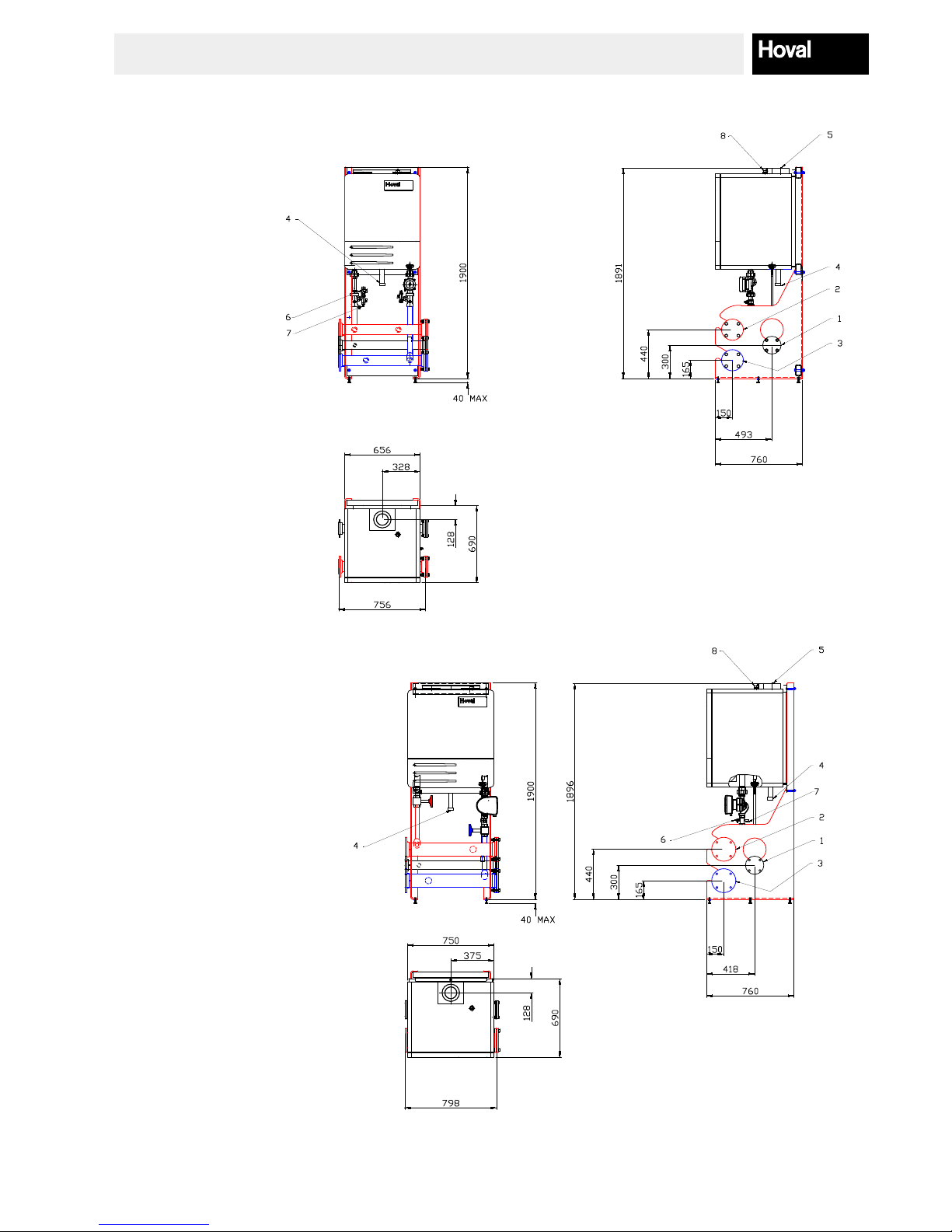
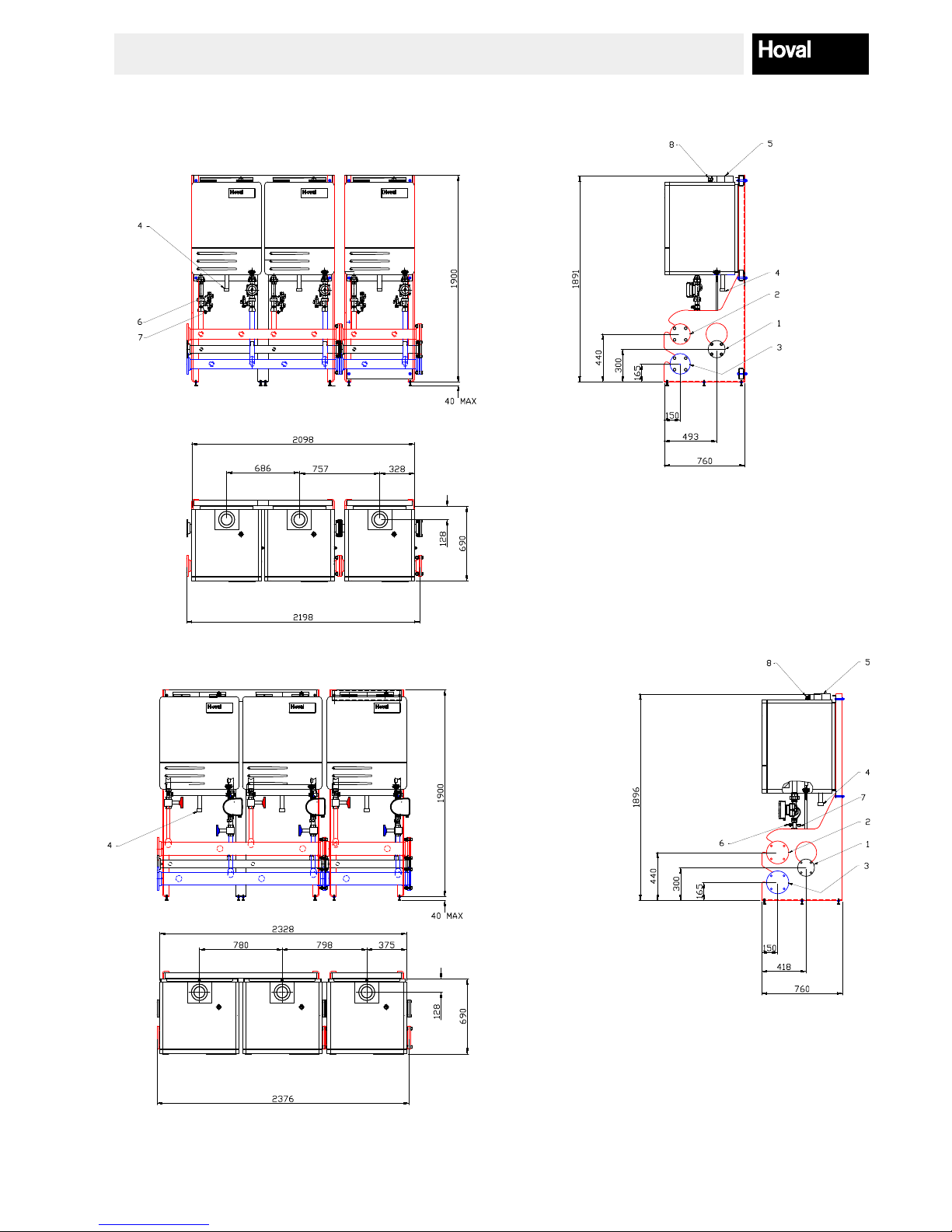
3.5. Technical Drawings, cascade in-line frame mounted
Connections
1. Gas DN65 PN6
2. Heating Flow DN80 PN6
3. Heating Return DN80 PN6
4. Condensate Drain trap DN40
5. Flue Concentric 100/150mm
6. Safety Valve R1”
7. Boiler Drain G1”
Connections
1. Gas DN65 PN6
2. Heating Flow DN100 PN6
3. Heating Return DN100 PN6
4. Condensate Drain DN40
5. Flue Concentric 100/150mm
6. Safety Valve R1”
7. Boiler Drain G¾”
Note: Condensate drainage, uing, safety valve discharge and boiler drain pipework to be supplied and tted by the installer (not by Hoval)
Blanking anges can be tted either side of the header assembly to suit site requirements
Optional low loss header or air/dirt seperator not shown
One boiler, in-line frame mounted - 1 x TopGas 60 (7015818), 1 x TopGas 80 (7015865)
One boilers, in-line frame mounted - 1 x TopGas 100 (7015799) , 1 x TopGas 120 (7015871)
12
TopGas Cascade 60 - 720 kW
4215256-00 - 11/16
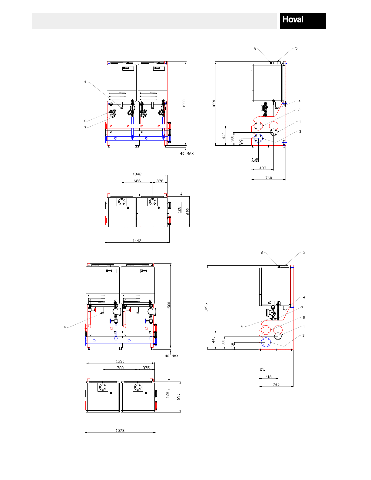
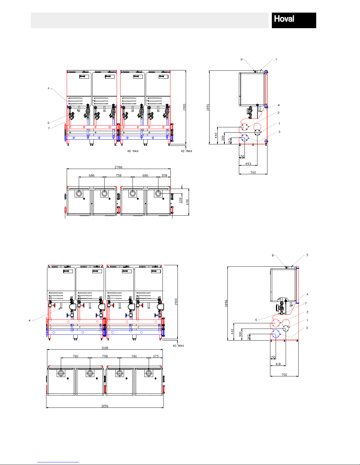
3.5. Technical Drawings, cascade in-line frame mounted
Connections
1. Gas DN65 PN6
2. Heating Flow DN100 PN6
3. Heating Return DN100 PN6
4. Condensate Drain DN40
5. Flue Concentric 100/150mm
6. Safety Valve R1”
7. Boiler Drain G¾”
Note: Condensate drainage, uing, safety valve discharge and boiler drain pipework to be supplied and tted by the installer (not by Hoval)
Blanking anges can be tted either side of the header assembly to suit site requirements
Optional low loss header or air/dirt seperator not shown
Two boilers, in-line frame mounted - 2 x TopGas 60 (7015839) , 2 x TopGas 80 (7015864)
Two boilers, in-line frame mounted - 2 x TopGas 100 (7015773), 2 x TopGas 120 (7015870)
Connections
1. Gas DN65 PN6
2. Heating Flow DN80 PN6
3. Heating Return DN80 PN6
4. Condensate Drain trap DN40
5. Flue Concentric 100/150mm
6. Safety Valve R1”
7. Boiler Drain G1”
13
TopGas Cascade 60 - 720 kW
4215256-00 - 11/16
Connections
1. Gas DN65 PN6
2. Heating Flow DN100 PN6
3. Heating Return DN100 PN6
4. Condensate Drain DN40
5. Flue Concentric 100/150mm
6. Safety Valve R1”
7. Boiler Drain G¾”
Note: Condensate drainage, uing, safety valve discharge and boiler drain pipework to be supplied and tted by the installer (not by Hoval)
Blanking anges can be tted either side of the header assembly to suit site requirements
Optional low loss header or air/dirt seperator not shown
Three boilers, in-line frame mounted - 3 x TopGas 60 (7015840), 3 x TopGas 80 (7015863)
Three boilers, in-line frame mounted - 3 x TopGas 100 (7015812), 3 x TopGas 120 (7015869)
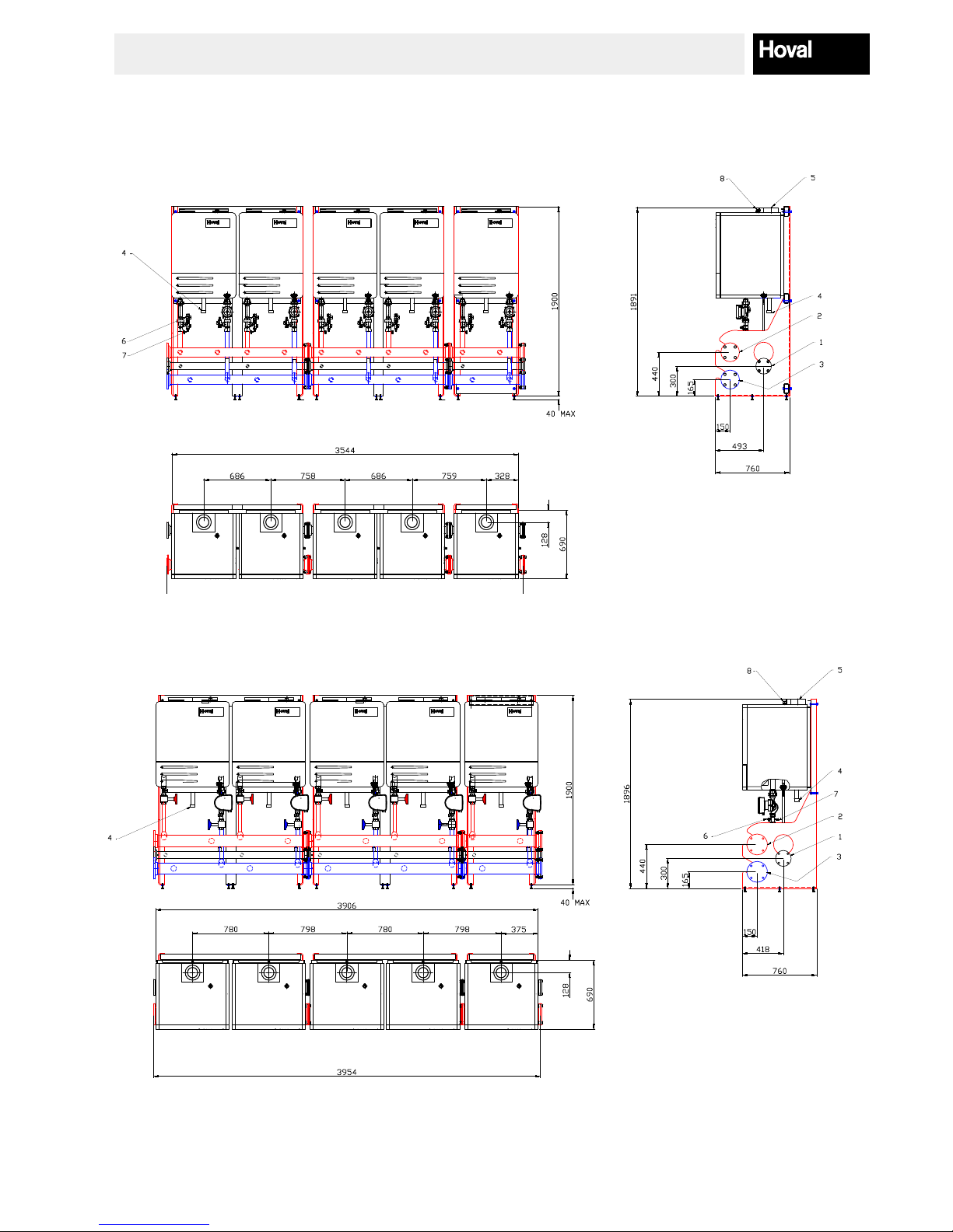
3.5. Technical Drawings, cascade in-line frame mounted
Connections
1. Gas DN65 PN6
2. Heating Flow DN80 PN6
3. Heating Return DN80 PN6
4. Condensate Drain trap DN40
5. Flue Concentric 100/150mm
6. Safety Valve R1”
7. Boiler Drain G1”
14
TopGas Cascade 60 - 720 kW
4215256-00 - 11/16
Connections
1. Gas DN65 PN6
2. Heating Flow DN100 PN6
3. Heating Return DN100 PN6
4. Condensate Drain DN40
5. Flue Concentric 100/150mm
6. Safety Valve R1”
7. Boiler Drain G¾”
Note: Condensate drainage, uing, safety valve discharge and boiler drain pipework to be supplied and tted by the installer (not by Hoval)
Blanking anges can be tted either side of the header assembly to suit site requirements
Optional low loss header or air/dirt seperator not shown
Four boilers, in-line frame mounted - 4 x TopGas 60 (7015841), 4 x TopGas 80 (7015862)
Four boilers, in-line frame mounted - 4 x TopGas 100 (7015813), 4 x TopGas 120 (7015868)
3.5. Technical Drawings, cascade in-line frame mounted
Connections
1. Gas DN65 PN6
2. Heating Flow DN80 PN6
3. Heating Return DN80 PN6
4. Condensate Drain trap DN40
5. Flue Concentric 100/150mm
6. Safety Valve R1”
7. Boiler Drain G1”
15
TopGas Cascade 60 - 720 kW
4215256-00 - 11/16
Connections
1. Gas DN65 PN6
2. Heating Flow DN100 PN6
3. Heating Return DN100 PN6
4. Condensate Drain DN40
5. Flue Concentric 100/150mm
6. Safety Valve R1”
7. Boiler Drain G¾”
Note: Condensate drainage, uing, safety valve discharge and boiler drain pipework to be supplied and tted by the installer (not by Hoval)
Blanking anges can be tted either side of the header assembly to suit site requirements
Optional low loss header or air/dirt seperator not shown
Five boilers, in-line frame mounted - 5 x TopGas 60 (7015842), 5 x TopGas80 (7015861)
Five boilers, in-line frame mounted - 5 x TopGas 100 (7015814), 5 x TopGas 120 (7015867)
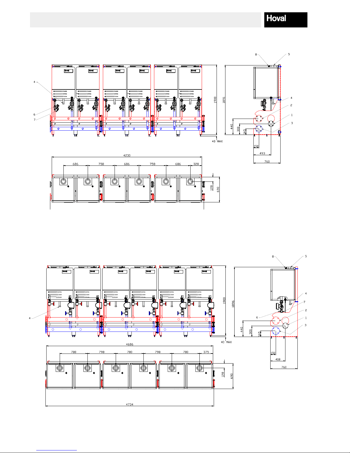
3.5. Technical Drawings, cascade in-line frame mounted
Connections
1. Gas DN65 PN6
2. Heating Flow DN80 PN6
3. Heating Return DN80 PN6
4. Condensate Drain trap DN40
5. Flue Concentric 100/150mm
6. Safety Valve R1”
7. Boiler Drain G1”
16
TopGas Cascade 60 - 720 kW
4215256-00 - 11/16
Connections
1. Gas DN65 PN6
2. Heating Flow DN100 PN6
3. Heating Return DN100 PN6
4. Condensate Drain DN40
5. Flue Concentric 100/150mm
6. Safety Valve R1”
7. Boiler Drain G¾”
Note: Condensate drainage, uing, safety valve discharge and boiler drain pipework to be supplied and tted by the installer (not by Hoval)
Blanking anges can be tted either side of the header assembly to suit site requirements
Optional low loss header or air/dirt seperator not shown
Six boilers, in-line frame mounted - 6 x TopGas 60 (7015843), 6 x TopGas 80 (7015860)
Six boilers, in-line frame mounted - 6 x TopGas 100 (7015815), 6 x TopGas 120 (7015866)
3.5. Technical Drawings, cascade in-line frame mounted
Connections
1. Gas DN65 PN6
2. Heating Flow DN80 PN6
3. Heating Return DN80 PN6
4. Condensate Drain trap DN40
5. Flue Concentric 100/150mm
6. Safety Valve R1”
7. Boiler Drain G1”

17
TopGas Cascade 60 - 720 kW
4215256-00 - 11/16
Connections
1. Gas DN65 PN6
2. Heating Flow DN100 PN6
3. Heating Return DN100 PN6
4. Condensate Drain DN40
5. Flue Concentric 100/150mm
6. Safety Valve R1”
7. Boiler Drain G¾”
Note: Condensate drainage, uing, safety valve discharge and boiler drain pipework to be supplied and tted by the installer (not by Hoval)
Blanking anges can be tted either side of the header assembly to suit site requirements
Optional low loss header or air/dirt seperator not shown
Two boilers, back to back frame mounted - 2 x TopGas 60 (7015844), 2 x TopGas 80 (7015824)
Two boilers, back to back frame mounted - 2 x TopGas 100 (7015801), 2 x TopGas 120 (7015859)
3.6. Technical Drawings, cascade back to back frame mounted
Connections
1. Gas DN65 PN6
2. Heating Flow DN80 PN6
3. Heating Return DN80 PN6
4. Condensate Drain trap DN40
5. Flue Concentric 100/150mm
6. Safety Valve R1”
7. Boiler Drain G1”

18
TopGas Cascade 60 - 720 kW
4215256-00 - 11/16
Connections
1. Gas DN65 PN6
2. Heating Flow DN100 PN6
3. Heating Return DN100 PN6
4. Condensate Drain DN40
5. Flue Concentric 100/150mm
6. Safety Valve R1”
7. Boiler Drain G¾”
Note: Condensate drainage, uing, safety valve discharge and boiler drain pipework to be supplied and tted by the installer (not by Hoval)
Blanking anges can be tted either side of the header assembly to suit site requirements
Optional low loss header or air/dirt seperator not shown
Three boilers, back to back frame mounted - 3 x TopGas 60 (7015845), 3 x TopGas 80 (7015823)
Three boilers, back to back frame mounted - 3 x TopGas 100 (7015800), 3 x TopGas 120 (7015828)
3.6. Technical Drawings, cascade back to back frame mounted
Connections
1. Gas DN65 PN6
2. Heating Flow DN80 PN6
3. Heating Return DN80 PN6
4. Condensate Drain trap DN40
5. Flue Concentric 100/150mm
6. Safety Valve R1”
7. Boiler Drain G1”

19
TopGas Cascade 60 - 720 kW
4215256-00 - 11/16
Connections
1. Gas DN65 PN6
2. Heating Flow DN100 PN6
3. Heating Return DN100 PN6
4. Condensate Drain DN40
5. Flue Concentric 100/150mm
6. Safety Valve R1”
7. Boiler Drain G¾”
Note: Condensate drainage, uing, safety valve discharge and boiler drain pipework to be supplied and tted by the installer (not by Hoval)
Blanking anges can be tted either side of the header assembly to suit site requirements
Optional low loss header or air/dirt seperator not shown
Four boilers, back to back frame mounted - 4 x TopGas 60 (7015846), 4 x TopGas 80 (7015822)
Four boilers, back to back frame mounted - 4 x TopGas 100 (7015802), 4 x TopGas 120 (7015827)
3.6. Technical Drawings, cascade back to back frame mounted
Connections
1. Gas DN65 PN6
2. Heating Flow DN80 PN6
3. Heating Return DN80 PN6
4. Condensate Drain trap DN40
5. Flue Concentric 100/150mm
6. Safety Valve R1”
7. Boiler Drain G1”

20
TopGas Cascade 60 - 720 kW
4215256-00 - 11/16
Connections
1. Gas DN65 PN6
2. Heating Flow DN100 PN6
3. Heating Return DN100 PN6
4. Condensate Drain DN40
5. Flue Concentric 100/150mm
6. Safety Valve R1”
7. Boiler Drain G¾”
Note: Condensate drainage, uing, safety valve discharge and boiler drain pipework to be supplied and tted by the installer (not by Hoval)
Blanking anges can be tted either side of the header assembly to suit site requirements
Optional low loss header or air/dirt seperator not shown
Five boilers, back to back frame mounted - 5 x TopGas 60 (7015847), 5 x TopGas 80 (7015821)
Five boilers, back to back frame mounted - 5 x TopGas 100 (7015816), 5 x TopGas 120 (7015826)
3.6. Technical Drawings, cascade back to back frame mounted
Connections
1. Gas DN65 PN6
2. Heating Flow DN80 PN6
3. Heating Return DN80 PN6
4. Condensate Drain trap DN40
5. Flue Concentric 100/150mm
6. Safety Valve R1”
7. Boiler Drain G1”

21
TopGas Cascade 60 - 720 kW
4215256-00 - 11/16
Connections
1. Gas DN65 PN6
2. Heating Flow DN100 PN6
3. Heating Return DN100 PN6
4. Condensate Drain DN40
5. Flue Concentric 100/150mm
6. Safety Valve R1”
7. Boiler Drain G¾”
Note: Condensate drainage, uing, safety valve discharge and boiler drain pipework to be supplied and tted by the installer (not by Hoval)
Blanking anges can be tted either side of the header assembly to suit site requirements
Optional low loss header or air/dirt seperator not shown
Six boilers, back to back frame mounted - 6 x TopGas 60 (7015848), 6 x TopGas 80 (7015820)
Six boilers, back to back frame mounted - 6 x TopGas 100 (7015817), 6 x TopGas 120 (7015825)
3.6. Technical Drawings, cascade back to back frame mounted
Connections
1. Gas DN65 PN6
2. Heating Flow DN80 PN6
3. Heating Return DN80 PN6
4. Condensate Drain trap DN40
5. Flue Concentric 100/150mm
6. Safety Valve R1”
7. Boiler Drain G1”

22
TopGas Cascade 60 - 720 kW
4215256-00 - 11/16
3.7. Technical Drawings, optional single and two boiler low loss headers
Single or two TopGas 80 boiler low loss header (2057322)
Please see Accessories section for further information
Single TopGas 100,120 boiler low loss header (6043445)
Connections
1. Primary Flow DN100 PN6
2. Primary Return DN100 PN6
3. Secondary Flow DN100 PN6
4. Secondary Return DN100 PN6
150
650
270
450
75
80
500
2 1/2" BSP
Boiler Return
2 1/2" BSP
System Return
2 1/2"
Boiler Flow
2 1/2"
System Flow
150
Single TopGas 60 boiler low loss header (2057320)
83
234
35
330
90
400
171
1" BSP
Boiler Return
1 1/2" BSP
System Return
1" BSP
Boiler Flow
1 1/2" BSP
System Flow
90
Please see Accessories section for further information
Please see Accessories section for further information

23
TopGas Cascade 60 - 720 kW
4215256-00 - 11/16
3.8. Technical Drawings, optional cascade low loss headers
Low loss header for all TopGas 100,120 cascades (6042824)
Connections
1. Primary Flow DN80 PN6
2. Primary Return DN80 PN6
3. Secondary Flow DN125 PN6
4. Secondary Return DN125 PN6
5. Automatic Air Vent Connection 1/2” BSP
6. Pocket Connection 1/2” BSP (plugged)
7. Drain Point 1/2” BSP (plugged)
Connections
1. Primary Flow DN100 PN6
2. Primary Return DN100 PN6
3. Secondary Flow DN150 PN6
4. Secondary Return DN150 PN6
5. Automatic Air Vent Connection 1/2” BSP
6. Pocket Connection 1/2” BSP (plugged)
7. Drain Point 1/2” BSP (plugged)
Low Loss Herader for TopGas 100/120 cascades (6042824)
Please see Accessories section for further information
Please see Accessories section for further information
Low Loss Herader for TopGas 45,60 & 80 cascades (6042897)
Low loss header for all TopGas 60,80 cascades (6034283)

24
TopGas Cascade 60 - 720 kW
4215256-00 - 11/16
3.9. Technical Drawings, optional cascade air and dirt separators
Air and dirt separator for all TopGas 60 and TopGas 80 cascades (2067549)
Air and dirt separator for all TopGas 100 and TopGas 120 cascades (2066122)
Connections
1. Primary Flow DN80 PN6
2. Primary Return DN80 PN6
3. Secondary Flow DN125 PN6
4. Secondary Return DN125 PN16
5. Automatic Air Vent
6. Pocket Connection 1/2” BSP (plugged)
7. Drain Valve 1/2” BSP (plugged)
Connections
1. Primary Flow DN100 PN6
2. Primary Return DN100 PN6
3. Secondary Flow DN150 PN6
4. Secondary Return DN150 PN6
5. Automatic Air Vent
6. Pocket Connection 1/2” BSP (plugged)
7. Drain Valve 1/2” BSP (plugged)
Air Dirt Seperator for TopGas 100 & 120 Cascades
Please see Accessories section for further information
Please see Accessories section for further information

25
TopGas Cascade 60 - 720 kW
4215256-00 - 11/16
4. Installation Requirements
4.3. Water Quality
The heating water must be treated in the TopGas Cascade to the
correct standard. Specic information can be found in the TopGas
Technical information Installation instructions document:
TopGas 35-120, document: 4214 783
The system heating water must be tested anually as a minimum
but Hoval recommend this to be done twice a year or after
every drain down and re-ll. If the water treatment specialist
recommends that this needs to be done more frequently please
follow their advice.
On account of the danger of spot corrosion the chloride, nitrate
and sulphate contents of the heating water must not exceed
200mg/l in total.
The pH value of the heating water should lie between 8,0 and 8,5
after 6 - 12 weeks of heating operation.
The boilers have aluminium heat exchangers which are in contact
with the heating water: Any inhibitors used must take account
of this and specialist advice should be sought prior to lling the
system based on local water quality conditions.
4.4. Gas Connection
The gas installation must fully conform with IGE/UP/2 and all re-
lated regulations.
The incoming natural gas supply to the TopGas Cascade must be
between 18-50 mbar with all connected appliances at full output.
For LPG this must be between 37-50 mbar.
All gas pipework must be tested and purged in accordance with
IGE/UP/1 or IGE/UP/1A.
Any gas work performed must be done by competent persons
holding a valid qualication.
4.1. Hydraulic Installation
Water from each safety valve discharge can cause severe burns.
Install the safety valve to ensure that there is no danger to other
persons. Route the safety valve discharge pipe to a tundish and
pipe to drain (not supplied by Hoval).
Flush the heating installation thoroughly prior to installation as
any foregin bodies or contaminants in the pipework may damage
the boiler.
If oxygen ingress is possible ensure that de-aeration equipment
is installed. If the plant is topped up with raw water ensure the
overall water quality still meets the required specication. The
totalamountofllingandreplacementheatingsystemwater
which is used throughout the total service life of the boiler
must not exceed three times the service capacity of the
plant.
4.2. Recommendations
It is recommended that each system should be lled and relled
with treated water and specialist companies will be able to advise
in this respect. Before lling check the following:
• All connections are made and tightened
• Sensor and instrument pockets are tted and water tight
• Spare sockets are tted with plugs and are water tight
• All valves in the heating circuit are open
• The installation is completely vented
• if a pressurisation unit is installed reference should be made
to the manufacturers lling instructions and applied
• The installation is fully ushed
• A suitable strainer and air/dirt separator are tted to protect
the equipment supplied.
For connection to the system a hydraulic header has to be used.
Hoval offer an optional low loss header kit or an air and dirt
separator that can act as a hydraulic header between the boiler
cascade and the heating system. These options should be
installed adjacent to the boiler cascade and advice should be
sought from Hoval technical if an alternative method is to be
adopted.
The pump set supplied with each boiler in the cascade is sized
to provide a ΔT of 20 K across each boiler ow and return. An
electrical ying lead is provided for the installer to connect each
pump to it’s respective TopGas boiler. A minimum ow must be
maintained through a boiler that is ring or being called to re. As
standard the TopGas boilers have a pump over-run feature that
maintains water ow through the boilers for ve minutes after it
has completed its ring sequence.
To allow the boiler to operate correctly it must have a minimum
water pressure of 1 bar. If this is not present an error code P27
will be displayed on each individual boiler control panel and the
boiler will not operate.
IMPORTANT NOTE:
Following assembly of the TopGas
Cascade arrangement it is the installer’s
responsibility to carry out suitable
water-side and gas-side pressure tests
and a ue system tightness test. These
tests are to be carried out by suitably
qualiedpersonnel.

26
TopGas Cascade 60 - 720 kW
4215256-00 - 11/16
4.5. Flue Gas Connection, Chimney
Each boiler in the TopGas cascade must be tted with a ue to
safely exhaust the products of combustion from the plant room.
Each boiler can be congured such that it takes it air directly from
the boiler plant room (room air dependent) or via closed concentric
ue/air supply system (room sealed or room air independent).
In the case of room sealed operation each of the boilers within
the cascade must be tted with individual concentric (100/150mm)
ue.
The maximum length of the concentric ue allowable will depend
on the TopGas model and the proposed layout or route of the ue.
Where the boiler cascade takes its air supply directly from the
plant room, It is possible to combine one or more TopGas boilers
into a common ue duct, where each boiler within the cascade is
connected to a common duct or ducts via an individual ue con-
nection piece. In this case all boilers in the cascade should be
provided with the optional air inlet non-return ap (available as an
accessory for the TopGas 60-120) boilers or with an external non-
return ap (not Hoval supply).
In all cases the ue terminal positions should comply with the re-
quirements of BS 5440-1 in the case of cascades with a total heat
input <70 kW net CV basis, or the requirements of BS 6644 when
the aggregate heat input of the cascade >135 kW on a net CV ba-
sis (note that this may limit the number of low level horizontal ue
discharge options available).
Owing to the water vapour content and the relatively low tempera-
ture of the ue gases then further condensation can be expected
within the ue system and therefore provision must be made to
remove this from the ue with appropriate trapped drains. There
must be a fall on horizontal sections of the ue to prevent stand-
ing condensate, and the ue must be able to withstand the mildly
acidic nature of the condensate. The ue system must be pressure
tight and able to operate under a positive pressure without prod-
ucts of combustion escaping into the plant room or other parts of
the building that the ue passes through.
Where appliance is to be room sealed (LAS) then a Hoval ue
adaptor piece with sample points (part no. 2042406) must be tted
on the boiler to allow the boilers to be commissioned and serviced.
Only ue gas systems or components tested and approved should
be connected to the Hoval TopGas boiler or the Hoval TopGas
boiler cascade.
It is important that a ue sample point is tted on both sides of the
concentric ue system or on the ue side of a conventional ue.
4.6. Electrical Connections
The electrical installation must fully conform with BS7671 and all
other regulations.
Each boiler requires its own 230Vac, 10A power supply with an
isolator mounted locally to the boiler (not by Hoval).
When a TopGas Cascade is purchased with the TopTronic E cas-
cade control system each boiler will need to be connected together
with a three core communications cable (not by Hoval). Please
refer to the electrical wiring diagram supplied with the cascade
package. This will detail other optional electrical items that have
been purchased. See the Accessories section in this document
for futher details.
4.7. Ventilation
Sufcient air must be supplied to each boiler to ensure that the
requirements of combustion and cooling are met and to afford a
general level of ventilation in the plant room.
In ALL cases the necessary ventilation to the Hoval TopGas
cascade must be in line with the requirements set out in BS 6644,
IGE/UP/10 and any local requirements.
Cooling air around the boilers must be sufcient such that the
temperatures in the installation location do not exceed those listed
in BS 6644.
4.8. Automatic Air Vent
All TopGas boilers are tted with automatic air vents. These must
be left open and operative at ALL times! If the cap is closed then
damage will occur to the boilers.
4.9. Condensate Drainage
Each TopGas boiler is supplied with a condensate trap which must
be tted. This must then be piped to the drain but with a suitable
air gap between the discharge point and the drain or galley so this
pipe cannot pressurise (not by Hoval).
No isolating or non-return valves should be tted in the
condensate discharge pipework and the pipework material should
be suitable for use with condensate.

27
TopGas Cascade 60 - 720 kW
4215256-00 - 11/16
Find a suitable space and prepare the frame for assembly. Each frame will come with:
4 x 75mm M10 bolts (2056546) 2 x side plates
4 x M10 nuts (2042599) 1 x vertical centre support
8 x M10 washers (2042608) 2 x horizontal support arms
1 x 1/8” Gas test nipple (2056819)
1 x 1/4” to 1/8” reducing bush (2068414) 1 x horizontal cross bar
12 x 50mm M16 bolts (2053287)
12 x M16 nuts (2044783)
24 x M16 washers (2042610)
Flow, return and gas connection gaskets
8 x M10 adjustable feet (2067454)
2 x DN80 Unions (TG60, 80) 2067951
2 x DN100 Unions (TG100,120) 2043066
Insulation wrap on LTHW pipework (not shown)
Fit the adjustable feet to both the center support and both side
plates. Set to the correct length and tighten using a 22mm spanner.
5.TopGas Cascade Assembly, 2 boilers in-line and 3 or 4 boilers back to back
Lay out the frame work on the oor and ensure you have all correct
components. You will see M10 holes to the outside ends on both
support arms. Ensure these are at the bottom so they line up with
the side plates.
Support arms will have:
2 x 180mm M10 bolts (2056533)
2 x M10 nuts (2042599)
4 x M10 washers (2042608)
Screw the M10 bolts (2056533) through both support arms and
centre support with a washer (2042608) either side and tighten to
45Nm and stand the frame up.

28
TopGas Cascade 60 - 720 kW
4215256-00 - 11/16
Hold up the center piece and support arms and align with the side
piece. Place the M10 bolt (2056546) through the support arm and
through the side piece with a washer either side (if holes do not
align then adjust the feet as appropriate) and add the M10 nut
(2042599). Repeat this process for the other side and tighten bolts
to 45Nm.
The cross bar has an alignment hole in the middle of the underside
as shown in the picture to the right. This slots onto the top of the
centre support so that the holes at either end align with the holes
on the side pieces. Thread both the M10 bolt (2056546) through the
crossbar and side pieces with a washer either side, add the M10
nut, then tighten both to 45Nm.
Once you have bolted the center piece and side pieces together
you should have the stand as shown to the right. To ensure that the
frame is stable check with a spirit level.
The frame should now look like the image to the right. Please ensure
that all of the bolts have washers either side of the frame work and
are all tightened to 45Nm.

29
TopGas Cascade 60 - 720 kW
4215256-00 - 11/16
If the cascade arrangment purchased is a three or four boiler back
to back model, you will receive rear support legs as shown opposite.
These are to be tted onto the rear of the side plates as shown. You
will also recieve extension pipes that will connect the ex connections to the header. Each rear support will come with the xings:
2 x 75mm M10 bolts (2056546)
2 x M10 nuts (2042599)
4 x M10 washers (2042608)
3 x M8 adjustable feet (2067454)
Build as shown and tighten to 45Nm.
Fit the adjustable feet to both of the side plates. Set to the correct
length and tighten using a 22mm spanner.
5.1.1 Step 1: Build the frame (1 boiler inline 2 boiler back to back)
6 x 75mm M10 bolts (2056546) 2 x side plates
6 x M10 nuts (2042599) 2 x horizontal support beam
12 x M10 washers (2042608) 1 x horizontal cross bar
1 x 1/8” Gas test nipple (2056819)
1 x 1/4” to 1/8” reducing bush (2068414)
12 x 50mm M16 bolts (2053287)
12 x M16 nuts (2044783)
24 x M16 washers (2042610)
Flow, return and gas connection gaskets
6 x M10 adjustable feet (2067454)
2 x DN80 Unions (TG60, 80) (2067951)
2 x DN100 Unions (TG100,120) (2043066)

30
TopGas Cascade 60 - 720 kW
4215256-00 - 11/16
Hold the crossbar in place and thread the M10 bolts (2056546)
through the crossbar and the aligned hole in the framework. Tighten
the nuts after both bolts are through the holes to make the align-
ment easier.
Once you have bolted the crossbar piece to the frame then screw in
the engineering studs by hand into the installed inserts.
Hold the middle support beam in place and thread the M10 bolts
(2056546) through the beam and the aligned hole in the framework. Ensure that the holes are to the bottom of the beam for boiler
alignment. Tighten the nuts after both bolts are through the holes to
make the alignment easier.
Place the gas pipe into the respective hole and the ow pipe (top
slot) and the return pipe (bottom slot) and ensure they are securely
in place with the alignment slots, this will ensure that the connec-
tions are correctly aligned.
Hold the two side pieces in line and align the holes at the bottom with
the holes in the bottom support beam using the M10 bolts (2056546).
Tighten the nuts after both bolts are through the holes to make the
alignment easier.
Build as shown and tighten to 45Nm.
Build as shown and tighten to 45Nm.
Build as shown and tighten to 45Nm.

31
TopGas Cascade 60 - 720 kW
4215256-00 - 11/16
If there are multiple sets of headers in your installation please
connect them and tighten to 180Nm ensuring they have the correct
gaskets between them:
65mm NB - 110mm OD, 78mm ID (2056845)
80mm NB - 132mm OD, 90mm ID (2043206)
100mm NB - 165mm OD, 115mm ID (2043208)
Connect each TopGas boiler to the frame using:
2 x M10 engineering studs (2067745)
2 x M10 nuts (2042608)
Tighten to a maximum of 60Nm.
Ensure that the boiler is safely lifted into position using
appropriate lifting equipment.
5.2. Step 2: Mount the boilers
If the cascade arrangment purchased is a two boiler back to back
model, you will receive rear support legs as shown opposite. These
are to be tted onto the rear of the side plates as shown. You will
also receive extension pipes that will connect the ex connections to
the header. Each rear support will come with the xings:
1 x 75mm M10 bolts (2056546)
1x 35mm M10 bolts (2042537)
2 x M10 nuts (2042599)
4 x M10 washers (2042608)
2 x M8 adjustable feet (2067454)

32
TopGas Cascade 60 - 720 kW
4215256-00 - 11/16
Using PTFE tape (or other suitable thread sealing media), wrap both
sides of the 1” nipple (2043076) before screwing into the header.
Ensure sealing media used is suitable for natural gas.
Fit the nipple into the header and tighten ensuring a good seal is
made.
Fit the 1” gas isolation valve (2067892) to the nipple. On the outlet
of the gas isolation valve, t the TracPipe connector (2067994). Before tting apply PTFE tape (or other suitable thread sealing media).
Ensure sealing media used is suitable for natural gas. Screw into
the top of the valve and tighten ensuring a good seal is made. Note,
ensure that the valve is in the correct orientation, when the valve is
open the handle must point upwards.
Attach the 3/4” to 1” concentric reducer (2042714) to the gas con-
nection on the boiler and then t the TracPipe connector (2067994).
Before tting apply PTFE tape (or other suitable thread sealing me-
dia). Ensure sealing media used is suitable for natural gas. Screw
into both sides of the boss and tighten ensuring a good seal is made.
TopGas Cascade Assembly
5.3. Step 3: Pipe the gas from the header to the boilers

33
TopGas Cascade 60 - 720 kW
4215256-00 - 11/16
TopGas Cascade Assembly
Measure the gap between the two TracPipe connectors and cut the
28mm TracPipe to length using a rotary tube cutter. Cut between
corrugations. Take care not to tighten the pipe cutter too tightly as
it may cause deformations. You will have been supplied a 500mm
length of TracPipe per boiler TopGas 60,80,100,120 (2067839).
Measure carefully - do not cut this too short. Ensure the cut has a
good smooth edge.
Using a knife, cut back the insulation on the TracPipe approximately 25mm to allow the tting to slide onto the pipe.
Slide on the brass union and t the sealing washer to the next available full corrugation. Pull the brass union back over the sealing
washer once complete. Do this to both ends of the pipe.
Once the pipe is complete, t it to both connector ends to the ttings
now attached to the boiler and the header. Tighten these to a value
of 61Nm. Once complete apply tape to the exposed stainless steel
pipework as this will reduce the risk of any external damage.
Fit the loose 1/4” to 1/8” reducing bush into the 1/4” socket tted on
top of the horizontal gas header, then t
the 1/8” gas nipple into the bush using
suitable sealing media.

34
TopGas Cascade 60 - 720 kW
4215256-00 - 11/16
TopGas Cascade Assembly
Prepare all exible pipework nipples as below using PTFE tape (or
other suitable thread sealing media). There will be 4 off per boiler.
Please be aware that you do not apply PTFE tape to the side with
the at face suitable for a gasket.
Screw these nipples into the headers and also into the valve sets.
Tighten to ensure a good seal is made.
When installing a back to back arrangement you will be supplied
extention pieces for the ow, return and gas pipe that screw into the
connection on the header.
TopGas 100,120 Flow and Return Extension pipe (5041198)
TopGas 60,80 Flow and Return Extension pipe (5041200)
TopGas 60-120 Gas Extension pipe (5041199)
5.4.Step4:Connectthenipplestotheowandreturnheaders

35
TopGas Cascade 60 - 720 kW
4215256-00 - 11/16
TopGas Cascade Assembly
Fit the ow pipe valve set to the boiler complete with supplied gasket and union (2067951) and tighten. Ensure all valves are correctly
aligned as per the picture.
5.5.Step5:Connecttheboilertotheowandreturnheaders(TopGas60and80)
Fit the supplied circulation pump to the return connection of the
boiler with a gasket joint. Be aware of the ow direction, this should
be pointing up towards the boiler. When satised that all is correct
tighten the union (2067951).
Fit the remaining return pipe valve set to the underside of the pump
using the supplied gasket and tighten. Ensure all valves are correctly aligned as per the picture below. When complete t the two
piece pump insulation housing (2056817).
The pump will be supplied with a 2m long MOLEX connector lead
(2056730) that wires into terminals 25, N, E.
Arrange the pump (2056729) and valve set (6012948) ready to be
connected to the boiler. Please be aware that all of the gaskets
must be tted in the correct positions as shown in the picture on
the right.
Note: the pump may be different to the one shown in the
photograph.

36
TopGas Cascade 60 - 720 kW
4215256-00 - 11/16
5.5.1.Step5:Connecttheboilertotheowandreturnheaders(TopGas100and120)
Fit the ow pipe valve set to the boiler complete with supplied gasket and union (2043066) and tighten. Ensure all valves are correctly
aligned as per the picture.
Fit the supplied circulation pump (2064823) to the return connection
of the boiler with a gasket joint. Be aware of the ow direction, this
should be pointing up towards the boiler. When satised that all is
correct tighten the union (2043066).
Fit the remaining return pipe valve set to the underside of the pump
using the supplied gasket and tighten. Ensure all valves are correctly aligned as per the picture to the right. When complete t the
two piece pump insulation housing supplied with the pump.
The pump will be supplied with a 2m long MOLEX connector lead
(2068178) that wires into terminals 25, N, E.
Arrange the pump (2064823) and valve set (6042514) ready to be
connected to the boiler. Please be aware that all of the gaskets
must be tted in the correct positions as shown in the picture on
the right.
Note: the pump may be different to the one shown in the
photograph.

37
TopGas Cascade 60 - 720 kW
4215256-00 - 11/16
Fit one side of the exible pipe to the nipple on the header and the
other side to the respective valve. A gasket must be used at either
end to ensure a water tight seal. Tighten accordingly.
TopGas Cascade Assembly
Tighten the M16 nuts and bolts to 180Nm.
When assembled decide which end of the headers you would like to
connect the system pipework to. At the opposing end you need to t
blanking anges with their associated gaskets.
Theheatingsystemowandreturnpipeworkshouldbothconnect to the same end of the headers.
5.6.Step6:Connecttheblankinganges

38
TopGas Cascade 60 - 720 kW
4215256-00 - 11/16
5.7. Step 7: Fit the pre-formed insulation wrap
Fit the supplied pre-formed insulation wrap to the ow and return
headers, align the pre cut holes with the connections on the headers and push the insulation wrap together ensuring the the teeth on
the insulation wrap interlock.
Important Note:
Ifyouhaveabacktobackversionyouwillneedtotthepre-
formed insulation wrap before connecting the rear extension
pipes and connection sets.
5.8. Step 8: Fitting the back boiler connections
Fit the 1” gas isolation valve (2067892) to the extension pipe. On
the outlet of the gas isolation valve, t the TracPipe connector
(2067994). Before tting apply PTFE tape (or other suitable thread
sealing media). Ensure sealing media used is suitable for natural
gas.
.
Connect the ¾” connection to the 1” concentric reducer (see page
32) then follow all steps on page 33. Finally connect the 1” union on
the gas TracPipe onto the 1” nipple.

39
TopGas Cascade 60 - 720 kW
4215256-00 - 11/16
For the ow and return connections t the 1¼” union (TopGas
60,80) or 1½” union (TopGas 100,120) on the exible pipe to
the extension pipe. Before tting apply PTFE tape (or other
suitable thread sealing media). Tighten to ensure a good seal
is made.
See page 35 for the TopGas 60,80 or page 36 for TopGas
100,120 for pump and valve set connection instructions. Fit
the remaining side of the exible pipe to the respective valve.
A gasket must be used at either end to ensure a water tight
seal. Tighten accordingly.

40
TopGas Cascade 60 - 720 kW
4215256-00 - 11/16
6. Accessories - Hydraulics and Gas
6.1. Low loss header
Used to allow secondary system ow exibility.
Designed for a primary ∆T of 20°C.
Allows for the secondary side to work with a ∆T as low as 11°C.
Supplied with a 1/2” automatic air vent, plugged 1/2” drain
points and a plugged 1/2” BSP socket to accept an optional
cascade control ow temperature sensor (with pocket) where
required. Flanged on the primary side to connect directly to the
TopGas Cascade LTHW headers.
Two models avaiable:
DN80 PN6 inlet, DN125 PN6 outlet
For 2-6 x TopGas 60 and 2-6 x TopGas 80
DN100 PN6 inlet, DN150 PN6 outlet
For 2-6 x TopGas 100 and 2-6 x TopGas 120
6.2. Air and dirt separator
Effectively removes any dirt from the system whilst dispersing
any air present.
Used to allow secondary system ow exibility.
Designed for a primary ∆T of 20°C.
Allows for the secondary side to work with a ∆T as low as 11°C.
Supplied with a 1/2” automatic air vent, an 1/2” drain valve
and a plugged 1/2” BSP socket to accept an optional cascade
control ow temperature sensor (with pocket) where required.
Flanged on the primary side to connect directly to the TopGas
Cascade LTHW headers.
Two models avaiable:
DN80 PN6 inlet, DN125 PN6 outlet
For 1-6 x TopGas 60 and 1-6 x TopGas 80
DN100 PN6 inlet, DN150 PN6 outlet
For 1-6 x TopGas 100 and 1-6 x TopGas 120
ABOVE A STATIC HEAD OF 15 METRES A VACUUM
DEGASSER SHOULD BE FITTED AS WELL AS THE AIR
AND DIRT SEPARATOR. PLEASE CONSULT HOVAL
TECHNICAL FOR FURTHER INFORMATION (the static
height is taken from the installed location of the air and
dirt separator to the highest point in the system).
6034283
6042824
2067549
2066122

41
TopGas Cascade 60 - 720 kW
4215256-00 - 11/16
83
234
35
330
90
400
171
1" BSP
Boiler Flow
1 1/2" BSP
System Flow
Northgate
Newark
Nottinghamshire
NG24 1JN
THIS DRAWING IS COPYRIGHT OF HOVAL
AND SHALL NOT BE REPRODUCED WITHOUT PRIOR WRITTEN PERMISSION
TEL: 44(0 )1636 672711
FAX: 44(0 )1636 673532
www.hoval.co.uk
Drawing Status
Project Name
WorkInProgress
Northgate
Newark
Nottinghamshire
TEL: 44( 0 ) 1636 672711
FAX: 44( 0 ) 1636 673532
www.hoval.co.uk
6.3. TopGas 60 single boiler low loss header
Single TopGas 60 boiler low loss header
Complete with 1”BSP connections on the inlet and 1½” BSP on
the outlet.
2057320
6.4. TopGas 80 single or two boiler low loss header
Single or two TopGas 80 boiler low loss header
Complete with 2½” BSP connections on both the inlet and the
outlet.
2057322
6.6. Boiler Circulating pump, TopGas (60,80)
Seperate individual boiler A-rated circulating pump for TopGas
60,80.
Grundfos UPML 32-95 180 AUTO single phase pump with G2”
connections.
A 2m long electrical lead (with Molex connector) is available to
connect the pump to the boiler.
UPML 32-95 180 AUTO pump
Electrical connection lead
2056729
2056730
6.7. Pump insulation cover, TopGas (60,80)
Two piece insulation cover for Grundfos UPML 32-95 180
AUTO pump
2056817
6.5. TopGas 100,120 single boiler low loss header
Single TopGas 100 or TopGas120 boiler low loss header
Complete with DN100 PN6 anged connections on both the
inlet and the outlet.
6043445
83
234
35
330
90
400
171
1" BSP
Boiler Flow
1 1/2" BSP
System Flow
6.8. Boiler circulating pump, TopGas (100,120)
Seperate individual boiler A-rated circulating pump for TopGas
100,120.
Grundfos MAGNA 1 25-80 180 AUTO single phase pump with
G1½” connections.
A 2m long electrical lead is available to connect the pump to
the boiler.
Includes a two piece insulation cover
MAGNA 1 25-80 180 AUTO pump
Electrical connection lead
2064823
2068178
1
2
3
4

42
TopGas Cascade 60 - 720 kW
4215256-00 - 11/16
6.9.Boilerowandreturnconnectionvalveset,TopGas(60,80)
Connection set for TopGas (60,80)
For use with circulation pump mounted on the return connection.
consisting of:
Return:
Isolating valve R 1 ¼” with gland nut 2”. Side outlet branch with drain
cock and G ¾” connection for expansion vessel.
(Allows above Grundfos pump to be connected directly)
Flow:
Extension G 2” x L=180mm with integrated non-return valve. Isolating
valve R 1 ¼” with gland nut 2”. Side outlet branch with safety valve (3
bar) and drain cock.
6012948
6.12 Liquid gas conversion kit 619 568
6.11Gaslter
with measurement nozzle before and behind the lter inset (diameter: 9
mm)
Pore width of the lter inset < 50 µm
Max. pressure difference 10 mbar
Max. inlet pressure 100 mbar
Type Connection
Rp ¾″
Rp 1″
70612/6B 2007 995
70602/6B 2007 996
1
2
3
1
2
3
6.10.Boilerowandreturnconnectionvalveset,TopGas
(100,120)
Connection set for TopGas® (100,120)
For circulation pump mounted on the return connection
consisting of:
Return:
1½” x 1½” DN40 combined isolating ball valve, non-return valve,
safety valve (3bar) and drain cock.
Flow:
1½” x 1½” isolating ball valve.
Includes a pair of 1½” Female unions.
6042514

43
TopGas Cascade 60 - 720 kW
4215256-00 - 11/16
Accessories - Controls
Flow temperature guard
for underoor heating (per heating circuit 1
guard) 15-95 °C, differential gap 6 K, capillary
tube max. 700 mm, setting (visible from the outside) inside the housing cover
Clamp-on thermostat
RAK-TW1000.S
Thermostat with strap, without cable and plug
242 902
Cascade controls with
heating controller set TopTronic® E ZE1
When assembled the TopGas cascade
boilers can be individually controlled
via an external building management
system or can be sequenced by the
optional heating controller set
TopTronic®E ZE1 into the master boiler
with an additional TopTronic®E ZE3
modulettedintoalltheotherboilers
in the cascade. A wired connection must
bettedbetweeneachboileranda
commonowsensorttedintothe
pipework to allow control via the boiler(s).
Heating controller set TopTronic® E ZE1
(Can be built in) as supplement for basic boiler
control panel G04.
- Installation of the TopTronic
®
E basic module
heat generator in the controller
Notice
No additional module expansions or controller modules can be installed in the boiler
control panel! This means an additional mixer
circuit must be implemented using the TopTronic® E heating circuit/hot water module in
an external wall casing.
- Can be optionally networked with a total
of up to 16 controller modules (incl. solar
module)
Consisting of:
- TopTronic
®
E control module
- TopTronic® E basic module heat generator
- Rast-5 basic plug set
- tting accessories
- 1 pce. outdoor sensor AF/2P/K
- 1 pce. immersion sensor TF/2P/5/6T/S1,
L = 5.0 m with plug
- 1 pce. contact sensor ALF/2P/4/T/S1,
L = 4.0 m with plug
- cable set ZE1
Heating controller set TopTronic® E ZE3
Heating controller set TopTronic® E ZE3 is tted in
optional boilers 2-6. One TopTronic®E ZE3 module
should be ordered for each boiler.
For example:
4 x TopGas boilers part number includes:
1 x TopTronic® E touchscreen display
1 x TopTronic® E control module
4 x TopTronic® E ZE1 control
4 x TopTronic® E ZE3 module
Number of boilers Package part number
2 Boiler cascade
6043 453
3 Boiler cascade 6043 454
4 Boiler cascade 6043 455
5 Boiler cascade 6043 456
6 Boiler cascade 6043 457

44
TopGas Cascade 60 - 720 kW
4215256-00 - 11/16
6034 576
6037 062
6038 526
6038 507
6038 508
6038 509
6038 510
6034 575
TopTronic® E module expansions
for TopTronic® E basic module heat generator
Note
The supplementary plug set may have to be
ordered to implement functions differing from
the standard! Consult Hoval Technical for site
specic requirements.
+
Note
The ow rate sensor set must be ordered as
well.
TopTronic® E module expansion Universal
TTE-FE UNI
Expansion to the inputs and outputs of a controller module (basic module heat generator, heating circuit/domestic hot water module, solar
module, buffer module) for implementing vari-
ous functions
incl. tting accessories
Can be installed in:
Wall housing, control panel
TopTronic® E module expansion
heat accounting TTE-FE WMZ/EBZ
Expansion to the inputs and outputs for
the basic module heat generator for
implementing the following functions:
- Calculating total energy consumption
- Calculating the heat generator energy for
heating
- Calculating the heat generator energy for
hot water
incl. tting accessories
3x contact sensor ALF/2P/4/T L = 4.0 m
Can be installed in:
Wall housing
TopTronic® E module expansion heating
circuit TTE-FE HK
Expansion to the inputs and outputs of the basic
module heat generator or the heating circuit/domestic hot water module for implementing the
following functions:
- 1 heating circuit without mixer or
- 1 heating circuit with mixer
incl. tting accessories
1x contact sensor ALF/2P/4/T L = 4.0 m
Can be installed in:
Wall housing
Flow rate sensor sets
Size Connection Flow rate
l/min
DN 8 G ¾″ 0.9-15
DN 10 G ¾″ 1.8-32
DN 15 G 1″ 3.5-50
DN 20 G 1¼″ 5-85
DN 25 G 1½″ 9-150
ODER
OR

45
TopGas Cascade 60 - 720 kW
4215256-00 - 11/16
6034 499
6034 503
6034 571
6037 058
6037 057
6034 574
6037 071
6037 069
6037 070
6037 079
6037 078
6018 867
6022 797
6034 578
6034 579
6034 581
6035 563
6035 564
6035 565
6035 566
6038 533
2055 889
2055 888
2056 775
2056 776
2061 826
6038 551
6038 552
6039 253
Supplementary plug set
for basic module heat generator (TTE-WEZ)
for controller modules and module expansion TTE-FE
HK
TopTronic® E controller modules
TTE-HK/WW TopTronic® E heating circuit/
hot water module
TTE-SOL TopTronic® E solar module
TTE-PS TopTronic® E buffer module
TTE-MWA TopTronic® E measuring module
TopTronic® E room control modules
TTE-RBM TopTronic® E room control modules
easy white
comfort white
comfort black
Enhanced language package TopTronic® E
one SD card required per control module
Consisting of the following languages:
HU, CS, SK, RO, PL, TR, ES, HR, SR, PT,
NL, DA
TopTronic® E remote Gateway connection
TTE-GW TopTronic® E online LAN
TTE-GW TopTronic® E online WLAN
SMS remote control unit
System component SMS remote con-
trol unit
TopTronic® E interface modules
GLT module 0-10 V
Gateway module ModBus TCP/
RS485
Gateway module KNX
TopTronic® E wall casing
WG-190 Wall casing small
WG-360 Wall casing medium
WG-360 BM Wall casing medium with
control module cut-out
WG-510 Wall casing large
WG-510 BM Wall casing large with
control module cut-out
TopTronic® E sensors
AF/2P/K Outdoor sensor
TF/2P/5/6T Immersion sensor, L = 5.0 m
ALF/2P/4/T Contact sensor, L = 4.0 m
TF/1.1P/2.5S/6T Collector sensor, L = 2.5 m
System housing
System housing 182 mm
System housing 254 mm
Bivalent switch
Accessories for TopTronic® E

46
TopGas Cascade 60 - 720 kW
4215256-00 - 11/16
8. Accessories - Flues (Individual - concentric)
Ø100
Ø150
1095
1135
102
152
110
Ø100
Ø150
152
102
990 / 490 / 240
1000 / 500 / 250
Ø100
Ø150
95
100
45°
Ø102
Ø152
215
Ø100
Ø150
Ø100
Ø100
Ø150
Ø100
115
240
102
152
110
Ø100
Ø150
Ø152
Ø100
Ø100
Ø150
Ø100
115
240
102
152
110
Ø100
Ø150
102
152
Ø100
Ø150
Ø102
Ø152
215
Ø100
Ø150
102
152
110
Ø100
Ø150
Ø102
Ø152
90
95
100
45°
Ø102
Ø152
215
Ø100
Ø150
102
152
110
Ø100
Ø150
Ø102
Ø152
90
95
100
45°
125
135
Ø102
Ø152
93°
125
150
Ø102
Ø152
215
Ø100
Ø150
102
152
110
Ø100
Ø150
Ø102
Ø152
100
45°
125
135
Ø102
Ø152
93°
Ø150
Ø102
Ø152
215
Ø100
Ø150
8.1 Connection C100/150 to 2xE100PP
For separate routing of ue gases and combustion
Recommendation:
If the air inlet is near a noise sensitive place (window of bedroom,
terrace etc.) we recommend the use of a sound
absorber on the air inlet.
2015 244
8.2 1000mm extension (including support bracket)
8.3 500mm extension (including support bracket)
2042 409
2042 408
8.4 Vertical terminal (black) with cap (including support bracket)
2042 404
1095
1135
102
152
110
Ø100
Ø150
152
102
990 / 490 / 240
1000 / 500 / 250
Ø102
Ø152
90
95
100
45°
125
135
Ø102
Ø152
93°
125
150
Ø150
1230
Ø100
Ø150
680
1180
1290
160
Ø102
Ø152
215
Ø100
Ø150
152
102
152
102
490
500
240
250
Ø100
Ø100
Ø150
Ø100
115
240
8.5 Vertical adapter
Complete with 2 sample points.
2042406
8.6 Vertical adapter
Complete with condensing drain connection, siphon kit and 2
sample points.
2042 415
8.7 45° elbow
2042 411
8.8 90° elbow
2042 410
8.9 Support bracket
2042 414
102
152
110
Ø100
Ø150
Ø102
Ø152
90
95
100
45°
125
135
Ø102
Ø152
93°
125
150
Ø150
200
160
22° - 45°
Ø102
Ø152
215
Ø100
Ø150
8.10Leadpitchedroofashing
(to suit roof angle 25-45 degrees)
2042 412

47
TopGas Cascade 60 - 720 kW
4215256-00 - 11/16
102
152
110
Ø100
Ø150
Ø102
Ø152
90
95
100
45°
125
135
Ø102
Ø152
93°
125
150
Ø150
200
160
22° - 45°
390
40
Ø160
165
Ø102
Ø152
215
Ø100
Ø150
Ø100
Ø150
1095
1135
102
152
110
Ø100
Ø150
152
102
990 / 490 / 240
1000 / 500 / 250
Ø100
Ø150
Ø102
Ø152
90
95
100
45°
125
135
Ø102
Ø152
93°
125
150
Ø150
1230
Ø100
Ø150
680
1180
1290
200
160
22° - 45°
40
Ø160
165
Ø102
Ø152
215
Ø100
Ø150
152
102
Ø100
Ø150
152
102
Ø100
Ø150
490
500
240
250
Ø100
Ø100
Ø150
Ø100
115
240
140
1220 max
195
275
Wall
plate
Wall
plate
Wall
terminal
93 degree
bend
Vertical
adaptor
8.11Aluminiumatroofashing
2042 413
8.12 100/150 Wall terminal kit (for horizontal discharge)
Comprises of vertical adaptor, 93 degree elbow 2 wall plates and
a horizontal wall terminal. Max dimension can be extended by
use of extension pieces.
2042 405
All items nished white RAL 9016
Flue design (TopGas® 60-120)
• An adapter with sample points must be used (tted to the boiler ue outlet connection).
• The ue gas is very cool and saturated with moisture so there will be very little or no buoyancy to pull the gases up the chimney.
• The burner fan assists with the evacuation of the ue gases so there may be slight pressurisation of the ue.
• It is permissible for the condensate from the ue system to drain back through the boiler.
• Horizontal ue sections must be inclined back to the boiler (3
° minimum) to prevent condensate remaining in the ue.
• Flues must be designed to meet all current regulations / standards.
• See Technical data section for ue gas mass ow rates, temperatures, usable fan overpressure and ventilation requirements.
• The tables below are for guidance only.
Maximumuelengths(TopGas® 35-60)
100/150PPconcentricue(horizontaldischarge)
-
-
21
22
23
24
25
26
27
28
29
30
31
32
33
0 1 2 3
4
0
5
10
15
20
25
012 3 4 5 6
20
19
TopGas 60
TopGas 35-45
Horizontal flue gas pipe length (m)
Max flue height (m)
Horizontal flue gas pipe length (m)
Max flue height (m)
TopGas 35-45
TopGas 60
-
-
0
5
10
15
20
25
012 3 4 5 6
Horizontal flue gas pipe length (m)
Max flue height (m)
TopGas 35-45
TopGas 60
-
-
21
22
23
24
25
26
27
28
29
30
31
32
33
0 1 2 3
4
0
5
10
15
20
25
012 3 4 5 6
20
19
0
2
4
6
8
10
12
14
16
18
0 123 456
Horizontal flue gas pipe length (m)
Max flue height (m)
TopGas 60
TopGas 35
TopGas 45
TopGas 60
TopGas 35-45
Horizontal flue gas pipe length (m)
Max flue height (m)
Horizontal flue gas pipe length (m)
Max flue height (m)
TopGas 35-45
TopGas 60
100PPue(inchimneystack,provisionfor
room air is required)
100/150PPconcentricue(inchimneystack)
The above gures include for one 93 degree bend.
Additional 93 degree bends will have the effect of
reducing the length by 2.5 metres and 45 degree bends
will reduce the length by 1.5 metres. The ue lengths
stated will have no effect on the boiler output.
Where the boiler cascade takes its air supply directly from the plant room, it is possible to combine one or more TopGas boilers into
a common ue duct, where each boiler within the cascade is connected to a common duct or ducts via an individual ue connection
piece complete with a non-return ap or damper. In this case all boilers should be provided with an optional air inlet non-return ap
(available as an accessory for the TopGas 60-120 as above) or with an external non-return ap for the TopGas 35 and 45 (not Hoval
supply).
8.13 Air inlet non-return damper for TopGas® (60-120) only
Fitted inside the boiler casing to prevent back ow of ue gases
through an off-line cascade boiler. Cannot be used with models
35 and 45.
6036 265

48
TopGas Cascade 60 - 720 kW
4215256-00 - 11/16
9. Accessories - Flues (Individual - Plume kit)
TopGas aluminium plume kit. All include high performance EPDM seals.
9.1. Plume management kit
Plume management kit to direct products of combustion to
discharge at high level. Suitable for all models of TopGas
boiler.
1. Concentric horizontal - C100/150
2. Plume 90° elbow - DN100
3. Plume extension, 1m - DN100
4. Plume nose piece - DN100
5. Mounting bracket - DN100
6. Wall plate - C100/150
7. Flue clamp - C100/150
2060156
1
9.2. Plume 90° elbow
90° elbow, DN100, aluminium
2060159
9.3. Plume 45° elbow
45° elbow, DN100, aluminium
2060158
9.4. Plume extension
1m extension, DN100, aluminium
2060157
9.5. Plume nose piece
Nose piece, DN100, aluminium
2060160
7
6
2
2
45
3
All DN100 items nished black RAL 9005
Concentric horizontal and internal wall plate nished white RAL 9016

49
TopGas Cascade 60 - 720 kW
4215256-00 - 11/16
10. Typical Hydraulic Schematic
Legend:
AAV: Automatic air vent
AF: Outdoor temperature sensor
B1: Flow temperature limiter
B2: Flow temperature limiter
CWS: Cold water supply
DHWS: Domestic hot water supply
LLH: Optional low loss header (or air and dirt separator)
M5.1: Boiler circulation pump
M5.2: Boiler circulation pump
MK1: Mixed circuit heating pump
MK2: Mixed circuit heating pump
SF: Calorier temperature sensor
SLP: Calorier loading pump
ST: Strainer
SVLF: Common ow sensor
TTE-GW: Gateway module
TTE-RBM: Room control module
TTE-ZE1: Heating controller set
TTE-ZE3: Base module heat generator
VF1: Mixed circuit ow sensor
VF2: Mixed circuit ow sensor
YK1: Mixed circuit control valve
YK2: Mixed circuit control valve
SVLF
B1VF 1
TT
M K1
M
YK1
Dies ist ein
unerlaubter Weg!
Gehen Sie einen
Schritt zurück oder
löschen Sie dieses
Shape!
Sie haben die
Möglichkeit ein
neues Shape zu
nehmen!!!
hovhovalhovalhoval
hovalhovalhovalhov
Gas
P
TopGas
1
M5.1
Gas
Dies ist ein
unerlaubter Weg!
Gehen Sie einen
Schritt zurück oder
löschen Sie dieses
Shape!
Sie haben die
Möglichkeit ein
neues Shape zu
nehmen!!!
hovhovalhovalhoval
hovalhovalhovalhov
P
TopGas
2 - 6
M5.2
B1VF 2
TT
MK 2
M
YK2
DHWS
CWS
S LP
Dies ist ein
unerlaubter
Weg!
Gehen Sie
einen Schritt
zurück oder
löschen Sie
dieses Shape!
Sie haben die
Möglichkeit ein
neues Shape zu
nehmen!!!
hovhovalhoval
hovalhovalhova
lhovalhovalhov
alhovalhovalho
valhovalhovalh
ovalhovalhoval
hovalhovalhova
lhovalhovalhov
alhovalhovalho
valhovalhovalh
ovalhovalhoval
h
T
S F
AAV
LLH
ST
Typical heating system (not by Hoval)
TTE-ZE1
AF
RBM
TTE-GW
TTE-ZE3
Notes :
- This hydraulic schematic just shows
the basic principle. The installation
must be in accordance with local regu-
lations.
- With underfloor heating an over
temperature thermostat has to be
installed.
- Anti thermal siphon dip has to be
installed (ATS).
- Safety valve (SV) position on return
with optional connection set for
TopGas® (100,120).

50
TopGas Cascade 60 - 720 kW
4215256-00 - 11/16
All TopGas® boilers can be commissioned by our dedicated
service team.
For annual servicing of TopGas
®
boilers and other equipment
please contact our Hoval Service department.
TopGas
®
spares kits are available from our spares department.
Service: 01636 593413 or service@hoval.co.uk
Spares: 01636 593412 or spares@hoval.co.uk
Service

4215256 / 00 - 11/16
An expert partner
Technical advice
We are happy to assist you and your planning partners
in developing intelligent systems, allowing you to take
advantage of our expertise and the experience of our
specialists.
After sales
For specialist commissioning and maintenance of your
Hoval equipment, contact our service and spares
department.
Responsibilty for energy and environment
One-stop shopping
With us you can easily incorporate gas, oil, heat pump,
solar, CHP, or biomass energy solutions into
your heating system.
Hoval Ltd
Northgate
Newark-on-Trent
Nottinghamshire
NG24 1JN
United Kingdom
Phone 01636 672 711
Fax 01636 673 532
email boilersales@hoval.co.uk
www.hoval.co.uk
Hoval follows a policy of continued improvement and reserves the right to change specications without notice.
 Loading...