


Operating Instructions
50 cm Gas Cooker
GB
English, 1
HUG 52X HUG 52P HUG 52K HUG 52G 50HGP
Contents
GB
Introduction, 2
For Your Safety, 3
Installation Instructions, 4-6
Electrical Connection, 7
Burner and Nozzle Specifications, 8
Features, 8
Control Panel, 9
Electronic Minute Minder, 10
Hotplates, 11
Grill, 12
Top Oven, 13
Top Oven Cooking Charts, 14
Main Oven, 15
Main Oven Cooking Chart, 16
Using the Main Oven for Other Functions, 17 Care and Cleaning, 18-20
Cooking Results Not Satisfactory?, 21 Something Wrong with your cooker?, 21 Disposal of the appliance, 22 Guarantee Information, 23
Service Information, 24
|
us |
on |
|
|
24 |
|
|
phone 24 |
r |
||
you |
|||
|
24 |
|
|
Please08448activate |
|
||
to |
guarantee |
||
PLEASE PHONE US TO REGISTER YOUR APPLIANCE AND ACTIVATE YOUR PARTS GUARANTEE ON 08448 24 24 24
Introduction
To the Installer:
Before installation, fill in the product details on the back GB cover of this book.
The information can be found on the rating plate.
To the User:
You must read the instructions prior to installing and using the appliance and then retain them for future reference.
!Before operating your new appliance please read this instruction booklet carefully. It contains important information concerning the safe operation, installation and maintenance of the appliance.
!Please keep these operating instructions for future reference. Pass them on to possible new owners of the appliance.
Retention of this Instruction Book
This Instruction Book must be kept handy for reference as it contains important details on the safe and proper use of the appliance.
If you sell or pass the appliance to someone else, or move house and leave it behind, make sure this Book is also provided so the new owner can become familiar with the appliance and safety warnings.
Your new appliance is guaranteed* and will give lasting service. This guarantee is only applicable if the appliance has been installed in accordance with the installation instructions detailed in this booklet.
To help make best use of your cooking equipment, please read this booklet carefully.
The cooker is designed specifically for domestic use and responsibility will not be accepted for use in any other installation.
When the cooker is first used an odour may be emitted, this will cease after a period of use.
When first using the cooker ensure that the room is well ventilated (e.g. open a window or use an extractor fan) and that persons who may be sensitive to the odour avoid any fumes.
It is suggested that any pets be removed from the room until the smell has ceased. This odour is due to temporary finish on oven liners and elements and also any moisture absorbed by the insulation.
* The guarantee is subject to the provisions that the appliance:
(a)Has been used solely in accordance with the Users Instruction Book.
(b)Has been properly connected to a suitable supply voltage as stated on the rating plate attached to this equipment.
(c)Has not been subjected to misuse or accident or been modified or repaired by any person other than the authorised employee or agent.
(d)Has been correctly installed.
Our policy is one of continual improvement in design and development, therefore strict accuracy of illustrations and descriptions cannot be guaranteed.
This appliance conforms with the following European Economic Community directives:
-2006/95/EC of 12/12/06 (Low Voltage) and subsequent modifications;
-2004/108/EC of 15/12/04 (Electromagnetic Compatibility) and subsequent modifications;
-2009/142/EC of 30/11/09 (Gas) and subsequent modifications (only for models which use gas);
-93/68/EEC of 22/07/93 and subsequent modifications.
-2002/96/EC
-1275/2008 (Stand-by/ Off Mode)
Technical Characteristics
Top Oven
Usable Volume: 28 Litres
heating mode: Conventional
Main Oven
Usable Volume: 54 Litres
heating mode: Conventional
Voltage and Frequency
220-240V~ 50Hz
Mains frequency and voltage of the electric section and characteristics of the gas section
Your new cooker is guaranteed and will give lasting service.
The guarantee is only applicable if the cooker has been installed in accordance with the Installation Instructions.
The cooker is designed specifically for domestic use and responsibility will not be accepted for use in any other installation.
Model |
|
Gas section |
|
|
|
|
|
|
Class |
|
Rated power |
|
|
kW (1) |
|
|
|
|
|
|
|
|
|
HUG 52X |
|
|
|
HUG 52P |
II2H3+ |
|
12,30 (894 g/h - G30) |
HUG 52K |
|
||
HUG 52G |
|
|
(878 g/h - G31) |
50HGP |
|
|
|
|
|
|
|
(1) The values in g/h refer to the capacities with liquid gas (Butane, Propane).
PLEASE PHONE US TO REGISTER YOUR APPLIANCE AND ACTIVATE YOUR PARTS GUARANTEE ON 08448 24 24 24
2
For your Safety
Please read the precautions below before using your cooker.
ALWAYS . . .
ALWAYS |
makesureyouunderstandthecontrolsbeforeusing |
|
the cooker. |
ALWAYS |
check that all controls on the cooker are turned off |
|
after use. |
ALWAYS |
stand back when opening an oven door to allow |
|
heat to disperse. |
ALWAYS |
use dry, good quality oven gloves when removing |
|
items from the ovens. |
ALWAYS |
take care when removing items from the top oven/ |
|
grill when the main oven is on, as the contents may |
|
be hot. |
ALWAYS |
keeptheovenandgrilldoorsclosedwhenthecooker |
|
is not in use. |
ALWAYS |
place pans centrally over the hotplate burners and |
|
positionthemsothatthehandlescannotaccidentally |
|
be caught or knocked or become heated by other |
|
burners. |
ALWAYS |
keep the cooker clean, as a build up of |
|
grease or fat from cooking can cause a fire. |
ALWAYS |
allow the cooker to cool before cleaning. |
ALWAYS |
follow the basic principles of food handling and |
|
hygienetopreventthepossibilityofbacterialgrowth. |
ALWAYS |
keep ventilation slots clear of obstructions. |
ALWAYS |
turn off the electricity supply before cleaning or |
|
replacing an oven lamp. |
ALWAYS |
referservicingtogassaferegisteredapplianceservice |
|
engineers. |
ALWAYS |
The appliance must be used by adults only for the |
|
preparation of food, in accordance with the |
|
instructions outlined in this booklet. Any other use |
of the appliance (e.g. for heating the room) constitutes improper use and is dangerous. The manufacturermaynotbeheldliableforanydamage resultingfromimproper,incorrectandunreasonable use of the appliance.
|
|
|
|
|
|
NEVER |
allow anyone to sit or stand on any part of the cooker. |
|
|||
NEVER |
store items that children may attempt to reach above |
|
|||
GB |
|||||
|
the cooker. |
|
|||
NEVER |
heat up unopened food containers as pressure can |
|
|||
|
|||||
|
build up causing the container to burst. |
|
|||
NEVER |
store chemicals, food stuffs, pressurised containers in |
|
|||
|
or on the cooker, or in cabinets immediately above or |
|
|||
|
next to the cooker. |
|
|||
NEVER |
fill a deep fat frying pan more than 1/3 full of oil, and |
|
|||
|
neverusealid.DONOTLEAVEUNATTENDEDWHILE |
|
|||
|
COOKING. |
|
|||
NEVER |
placeflammableorplasticitemsonornearthehotplate. |
|
|||
NEVER |
use proprietary spillage collectors on the hotplate. |
|
|||
NEVER |
use the cooker as a room heater. |
|
|||
NEVER |
dry clothes or place other times over or near to the |
|
|||
|
hotplate or oven/gril doors. |
|
|||
NEVER |
weargarmentswithlongflowingsleeveswhilstcooking. |
|
|||
NEVER |
let children play with the appliance. |
|
|||
NEVER |
should the appliance be operated by people (including |
|
|||
|
children) with reduced physical, sensory or mental |
|
|||
|
capacities, by inexperienced individuals or by anyone |
|
|||
|
who is not familiar with the product. These individuals |
|
|||
|
should, at the very least, be supervised by someone |
|
|||
|
who assumes responsibility for their safety or receive |
|
|||
|
preliminary instructions relating to the operation of the |
|
|||
|
appliance. |
|
|||
NOTE: The use of a gas cooking appliance results in the production of heat and moisture in the room in which it is installed. Always ensure that the kitchen is well ventilated; keep natural ventilation holes open or install a mechanical ventilation device(mechanicalextractorhood).
In particular when using the grill or more than one hotplate burner, open a window if a mechanical ventilation device is not operating.
SAFETY ADVICE IN CASE OF A CHIP-PAN FIRE In the event of a chip pan fire or any other pan fire.
1.TURN OFF THE COOKER APPLIANCE AT THE WALL SWITCH.
2.COVER THE PAN WITH A FIRE BLANKET OR DAMP CLOTH, this will smother the flames and extinguish the fire. 3.LEAVE THE PAN TO COOL FOR AT LEAST 60 MINUTES BEFORE MOVING IT. Injuries are often caused by picking up a hot pan and rushing outside with it.
NEVER USE A FIRE EXTINGUISHER TO PUT OUT A PAN FIRE as the force
of the extinguisher is likely to tip the pan over. Never use water to extinguish oil or fat fires.
NEVER . . . |
|
NEVER |
leave children unsupervised where the cooker is |
|
installed as all surfaces will get hot during and after |
|
use. |
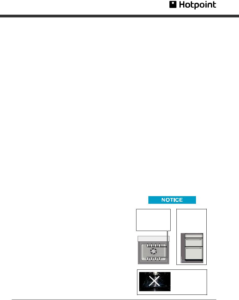
! VERY HOT SURFACES
FOOD OR GREASE ON THESE SURFACES COULD CAUSE
SMOKE AND POSSIBLY EVEN BURN
YOU MUST KEEP THE OVEN AND GRILL CAVITIES CLEAN
! ATTENTION
DURING INSTALLATION
THE FEET OF THE APPLIANCE MUST BE LOWERED SO THAT AN AIR GAP OF AT LEAST 10MM (1CM) IS LEFT BETWEEN THE BASE OF THE APPLIANCE AND THE FLOOR.
10 mm
! ATTENTION
WHEN USING THE MAIN OVEN YOU MUST ENSURE THAT THE BASE OF THE CAVITY IS NOT COVERED WITH ALUMINUM FOIL, UTENSIL OR ANY OTHER FORM OF COVERING. FAILURE TO DO THIS MAY RESULT IN THE CAVITY BEING DAMAGED.
PLEASE PHONE US TO REGISTER YOUR APPLIANCE AND ACTIVATE YOUR PARTS GUARANTEE ON 08448 24 24 24
3
Installation
The appliance must only be installed by a
GB competent person. In the UK, gas safe registered installers undertake to work to safe and satisfactory standards.
Before moving your cooker check that it is cool, and switch off at the cooker control unit. Movement of your cooker is most easily achieved by lifting the front as follows:
Open the grill door sufficiently to allow a comfortable grip on the underside front edge of the oven roof, avoiding any grill elements. (FIG. C)
! Take care in moving the cooker as it is heavy. Take care to ensure that any floor covering is not damaged.
Splashplate optional, apply to Parts Department (see Back Cover for contact number.)
The following instructions should be read by a qualified technician to ensure that the appliance is installed, regulated and technically serviced correctly in compliance with current regulations.
! Remember to unplug the appliance from the mains before regulating the appliance or carrying out any maintenance work.
Positioning
Important: this unit may be installed and used only in permanently ventilated rooms according to the British Standards Codes Of Practice: B.S. 6172/B.S. 5440, Par. 2 and B.S. 6891 Current Editions. The following requirements must be observed:
a) The cooker should not be installed in a bed sitting room with a volume of less than 20m3. If it is installed in a room of volume less than 5m3 an air vent of effective area of 110cm2 is required, if it is installed in a room of volume between 5m3 and 10m3 a supplementary airvent area of 50cm2 is required, if the volume exceeds 11m3 no airvent is required. However, if the room has a door or a window which opens directly to the outside no air vent is required even when the volume is between 5m3 and 11m3.
b ) During prolonged use of the appliance you may consider it necessary to open a window to the outside to improve ventilation.
c) If there are other fuel burning appliances in the same room, B.S.5440 Part 2 Current Edition, should, be consulted to determine the requisite air vent requirements.
Installation of the cooker
For a correct installation of the cooker the following precautions must be followed:
The height of the cooker can be adjusted by means of adjustable feet in the plinth (900mm - 930mm). Adjust the feet by tilting the cooker from the side. Then install the product into position.
NOTE: This appliance must not be fitted on a platform.
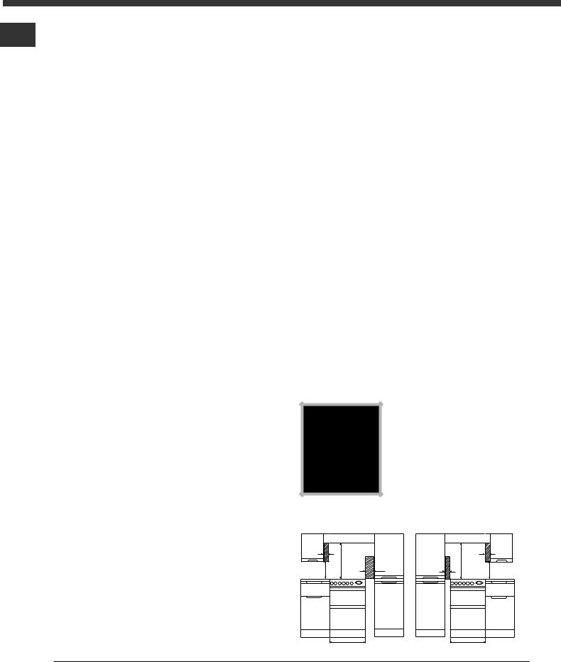
The cooker is designed to fit between kitchen cabinets spaced 500mm apart. The space either side need only be sufficient to allow withdrawal of the cooker for servicing. It can be used with cabinets one side or both as well as in a corner setting. It can also be used free-standing. Adjacent side walls which project above hob level, must not be nearer to the cooker than 150mm or 65mm (Fig. A) and should be protected by heat resistant material. Any overhanging surface or
cooker hood should not be nearer than 750mm(FigA)
a) The cooker may be located in a kitchen, a kitchen/diner or bed sitting room, but not in a bathroom or shower room.
b ) The hoods must be installed according to the requirements in the hood handbook.
c) The wall in contact with the back of the cooker must be of flameproof material.
d ) The cooker is fitted with a safety chain that must be attached to a hook, secured to the wall behind the appliance.

 ! Some models can have their
gas connection inverted. It is important to make sure the safety chain is always situated on the
side which corresponds to the  hose holder (Fig. B).
Tall cupboard on the right hand side of 50cm gas cooker
65 mm min |
min |
|
400 mm min |
750 mm |
150 mm min |
|
|
500 mm min
Fig.A
Tall cupboard on the left hand side of 50cm gas cooker
|
min |
65 mm min |
65 mm min |
750 mm |
400 mm min |
|
|
500 mm min
PLEASE PHONE US TO REGISTER YOUR APPLIANCE AND ACTIVATE YOUR PARTS GUARANTEE ON 08448 24 24 24
4
Installation
Moving the Cooker
Fig. B |
|
Fig. C |
Gas connection |
|
|
|
|
The cooker should |
|
|
be connected to the |
|
HOT PARTS |
gas-supply by a |
|
|
|
|
|
gas safe registered |
|
|
installer. During |
|
mm |
installation of this |
|
product it is |
|
|
600 |
|
|
essential to fit an |
|
|
|
|
|
|
approved gas tap to |
|
|
isolate the supply |
|
|
from the appliance |
for the convenience of any subsequent removal or servicing. Connection of the appliance to the gas mains or liquid gas must be carried out according to the prescribed regulation in force, and only after it is ascertained that it is adaptable to the type of gas to be used. If not, follow the instructions indicated in the paragraph headed “Adaptation to different gas types”. In the case of connection to liquid gas, by tank, use pressure regulators that conform to the regulation in force. The gas supply must be connected to the left of the appliance. Be sure that the hose does not pass through the rear of the cooker touching hot parts.
! make sure the supply pressure conforms with the values shown in the table entitled “Caracteristics of the burners and nozzles”.
When the cooker is installed between cabinets (recessed), the gas connection must be effected by an approved flexible hose with bayonet fitting
(BS 669 Current Edition). The gas inlet for the cookers is a threaded G 1/2 gas female fitting.
Connecting the gas supply
GB
To make the connection, a flexible hose should be used corresponding to the current gas regulations which are:
•the hose must never be at any point in its
|
lenght in contact with the “hot” parts |
of the |
cooker; |
• |
the hose must never be longer than 1,5 |
metre; |
|
• |
the hose must not be subject to any tension |
or torsional stress and it must not have any excessively narrow curves or bottlenecks;
•the hose must be easy to inspect along its
entire length to check its condition;
•the hose must always be in good condition,
never attempt to repair.
! the installation must comply with gas safety (installation and use) regulations 1984. In all cases
for the above, by low, a qualified, gas safe i approved engineer must be called for installation.
Disposing of the appliance
When disposing of the appliance please remove the plug by cutting the mains cable as close as possible to the plug body and dispose of it as described above.
Adapting the cooker to different types of gas
In order to adapt the cooker to a different type of gas with respect to the gas for which it was produced (indicated on the label attached to the lid), follow these steps:
a)replace the hose holder mounted on the appliance with that supplied in the bag of “cooker accessories”.
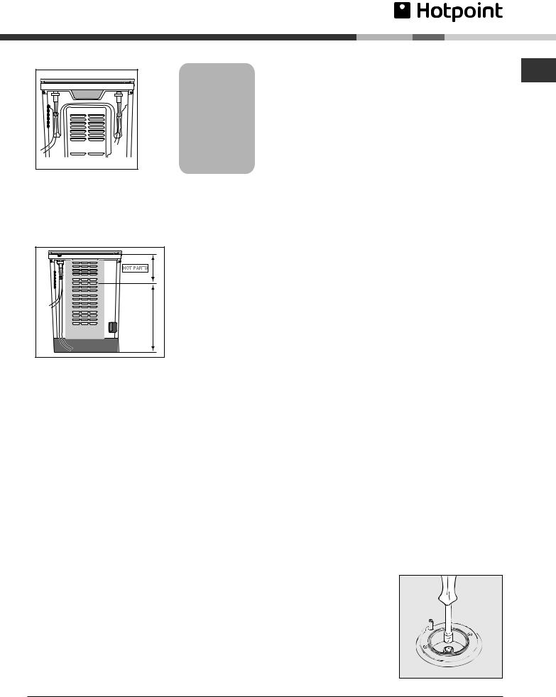
b)Replacing the burner nozzles on the hob:
•remove the grids and slide the burners from their housings;
• unscrew the nozzles
using a 7 mm socket spanner, and replace them with nozzles for
the new type of gas
(see table 1 “Burner and nozzle characteristics”).
•replace all the components by
repeating the steps in reverse order.
PLEASE PHONE US TO REGISTER YOUR APPLIANCE AND ACTIVATE YOUR PARTS GUARANTEE ON 08448 24 24 24
5
Installation
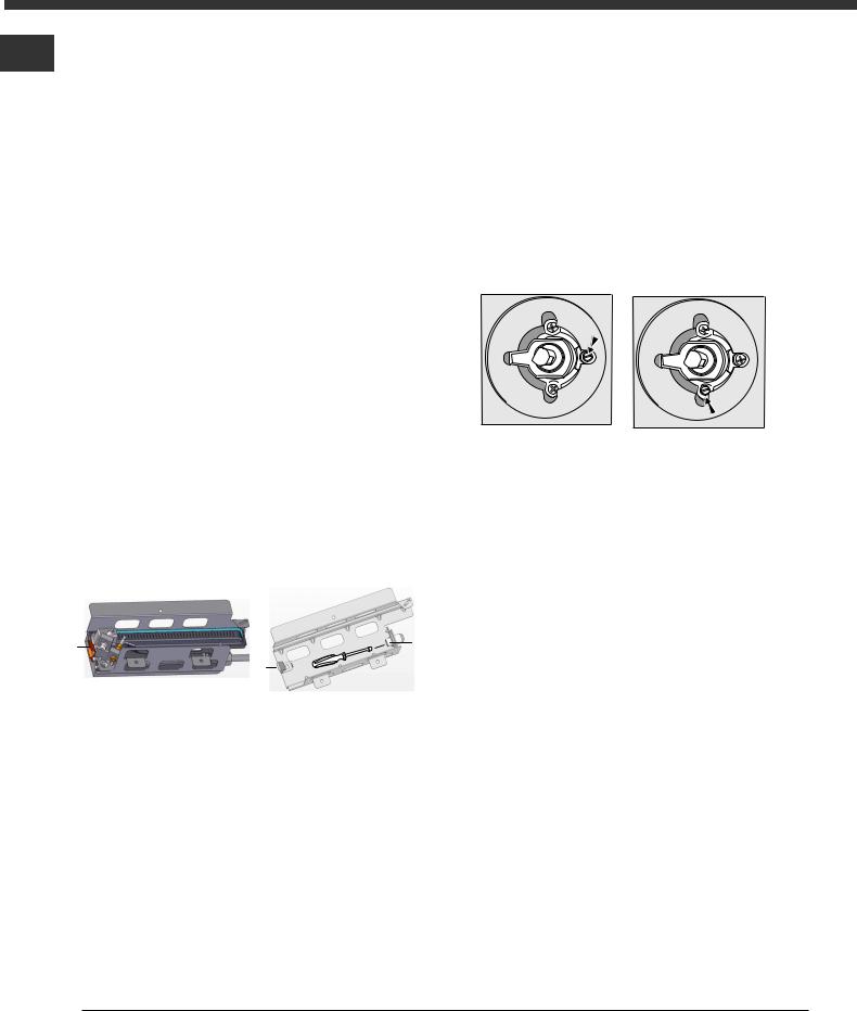
c)Minimum regulation of the hob burners:
GB
•turn the tap to minimum;
•remove the knob and adjust the regulation screw, which is positioned in or next to the tap pin, until the flame is small but steady.
!In the case of liquid gas, the
regulation screw must be screwed in to the bottom.
• check that the flame does not turn off when you turn the tap quickly from high to low.
d ) Regulating the primary air of the burners: The primary air of the burners requires no regulation.
Adapting to different types of gas (main and top oven)
In order to adapt the oven to a different type of gas with respect to the gas for which it was manufactured (indicated on the label), follow these simple steps:
a) Replacing the oven burner nozzle
•open the oven door fully
•pull out the sliding oven bottom
•unscrew the two screws and take off the shield protecting the burner (in main oven burner only).
Z
V
V
•Pry the fixing tab “V” and remove the oven burner
•Unscrew the oven burner nozzle using the socket spanner for the nozzles “Z”, or a 7 mm socket spanner, and replace it with a nozzle suited to the new type of gas (see Table 1).
Take particular care handling the spark plug wires and the thermocouple pipes.
•Replace all the parts, following the steps described above in the reverse order.
b ) Minimum regulation of the main and top gas oven burner with thermostat:
•light the burner as described in the
paragraph |
the oven knob” of the |
instruction booklet. |
|
•turn the knob to Max for about 10 minutes
and then turn the knob to the Min
setting;
•remove the knob;
•regulate the screw positioned outside the
thermostat pin until the flame is steady.
! In the case of liquid gas, the regulation screw must be screwed in to the bottom.
•check that the burner does not turn off when you turn the knob from Max to Min and and when you open and close the oven door quickly.
Adapting the gas grill to different types of gas Replacing the nozzle of the grill burner:
•Remove the enamelled baffle at the front of the grill (2 screws).
•Remove the screw on the right hand side of the burner and gently slide the burner off the injector.
•Using a 7mm socket, replace the grill injector as appropriate (see table 1).
•Re-assemble the burner and baffle.
!On completion of the operation, replace the old rating sticker with one indicating the new type of gas used. This sticker is available from our Service Centres.
Note
Should the pressure of the gas used be different (or vary) from the recommended pressure, it is necessary to fit a suitable pressure regulator onto the inlet pipe in compliance with current National Regulations relative to “regulators for channelled gas”.
PLEASE PHONE US TO REGISTER YOUR APPLIANCE AND ACTIVATE YOUR PARTS GUARANTEE ON 08448 24 24 24
6
Electrical Connection
Power supply voltage and frequency: 230-240V a.c. 50/60 Hz.
! The supply cable must be positioned so that it never reaches at any point a temperature 50°C higher than the room temperature. The cable must be routed away from the rear vents. Should you require it, you may use a longer cable, however, you must ensure that the cable supplied with the appliance is replaced by one of the same specifications in accordance with current standards and legislation.Your appliance is supplied with a 13 amp fused plug that can be plugged into a 13 amp socket for immediate use. Before using the appliance please read the instructions below.
WARNING - THIS APPLIANCE MUST BE EARTHED. THE FOLLOWING OPERATIONS SHOULD BE CARRIED OUT BY A QUALIFIED ELECTRICIAN.
Replacing the fuse:
When replacing a faulty fuse, a 13 amp ASTA approved fuse to BS 1362 should always be used, and the fuse cover re-fitted. If the fuse cover is lost, the plug must not be used until a replacement is obtained.
Replacement fuse covers:
If a replacement fuse cover is fitted, it must be of the correct colour as indicated by the coloured marking or the colour that is embossed in words on the base of the plug. Replacements can be obtained directly from your nearest Service Depot.
Removing the plug:
If your appliance has a non-rewireable moulded plug and you should wish to remove it to add a cable extension or to re-route the mains cable through partitions, units etc., please ensure that either:
•the plug is replaced by a fused 13 amp rewireable plug bearing the BSI mark of approval.
or:
•the mains cable is wired directly into a 13 amp cable outlet, controlled by a switch, (in compliance with BS 5733) which is accessible without moving the appliance.
! For appliances with a rating greater than 13 amp
(eg: electric hob, double ovens and freestanding GB electric cookers etc.) the mains cable must be wired
into a cooker output point with a rating of 45 amp. In this case the cable is not supplied.
Disposing of the plug:
Ensure that before disposing of the plug itself, you make the pins unusable so that it cannot be accidentally inserted into a socket. Instructions for connecting cable to an alternative plug:
! The wires in the mains lead are coloured in accordance with the following code:
Green & Yellow - Earth
Blue - Neutral
Brown - Live
If the colours of the wires in the mains lead do not correspond with the coloured markings identifying the terminals in your plug, proceed as follows:
Connect Green & Yellow wire to terminal marked “E” or 6 or coloured Green or Green & Yellow.
Connect Brown wire to terminal marked “L” or coloured Red.
Connect Blue wire to terminal marked “N” or coloured Black.
If a 13 amp plug (BS 1363) is used it must be fitted with a 13 amp fuse. A 15 amp plug must be protected by a 15 amp fuse, either in the plug or adaptor or at the distribution board. If you are in any doubt about the electrical supply to your machine, consult a qualified electrician before use.
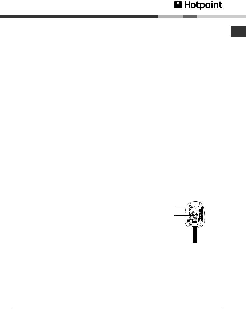
How to connect an alternative plug: |
|
|||
The wires in this mains |
|
|
||
|
|
|||
lead are coloured in |
|
GREEN & |
|
|
accordance with the |
|
YELLOW |
|
|
|
|
|
||
following code: |
|
|
BROWN |
13 amp fuse |
|
|
|
|
|
BLUE “NEUTRAL |
” |
BLUE |
CROSS-BAR |
|
|
CORD GRIP |
|||
(“N”) |
|
|
|
|
BROWN |
“LIVE” |
|
|
|
(“L”) |
|
|
|
|
GREEN AND |
|
|
|
|
YELLOW |
“EARTH” (“E”) |
|
||
WARNING.
If the electric supply fails to this appliance you must not use the grill or ovens.
PLEASE PHONE US TO REGISTER YOUR APPLIANCE AND ACTIVATE YOUR PARTS GUARANTEE ON 08448 24 24 24
7

Burner and Nozzle
Specifications
|
|
Table 1 |
|
|
|
|
|
|
|
Liquid Gas |
|
|
|
|
|
Natural Gas |
|
|
|
|
|||
GB |
|
|
|
|
|
|
|
|
|
|
|
|
|
|
|
||||||||
|
|
|
|
|
|
|
|
|
|
|
|
|
|
|
|
|
|
|
|
|
|
||
|
Burner |
|
Diameter |
Thermal Power |
By-Pass |
Nozzle |
Flow* |
|
Thermal Power |
|
Nozzle |
Flow* |
|
|
|||||||||
|
|
|
|
|
|
|
kW (p.c.s.*) |
1/100 |
1/100 |
g/h |
|
kW (p.c.s.*) |
1/100 |
l/h |
|
|
|||||||
|
|
|
|
(mm) |
|
Nominal |
|
Reduced |
(mm) |
(mm) |
*** |
|
** |
Nominal |
|
Reduced |
|
(mm) |
|
|
|
|
|
|
|
|
|
|
|
|
|
|
|
|
|
|
|||||||||||
|
|
|
|
|
|
|
|
|
|
|
|
|
|
|
|
|
|
|
|
|
|
|
|
|
|
Fast |
|
100 |
|
94 |
2,60 |
|
0,7 |
41 |
80 |
189 |
|
186 |
2,60 |
|
0,7 |
118 |
248 |
|
|
|
|
|
|
(Large)(R) |
|
|
|
|
|
|
|
|
|||||||||||||
|
|
|
|
|
|
|
|
|
|
|
|
|
|
|
|
|
|
|
|
|
|
|
|
|
|
Semi Fast |
|
75 |
|
69 |
1,90 |
|
0,4 |
30 |
70 |
138 |
|
136 |
1,90 |
|
0,4 |
104 |
181 |
|
|
|
|
|
|
(Medium)(S) |
|
|
|
|
|
|
|
|
|||||||||||||
|
|
|
|
|
|
|
|
|
|
|
|
|
|
|
|
|
|
|
|
|
|
|
|
|
|
Auxiliary |
|
51 |
|
46 |
1,00 |
|
0,4 |
30 |
52 |
73 |
|
71 |
1,00 |
|
0,4 |
76 |
95 |
|
|
|
|
|
|
(Small)(A) |
|
|
|
|
|
|
|
|
|||||||||||||
|
|
|
|
|
|
|
|
|
|
|
|
|
|
|
|
|
|
|
|
|
|
|
|
|
|
Main Oven |
|
- |
|
- |
2,60 |
|
0,6 |
34 |
71 |
189 |
|
186 |
2,60 |
|
0,6 |
115 |
248 |
|
|
|
|
|
|
Grill |
|
- |
|
- |
2,30 |
|
2,0 |
- |
75 |
167 |
|
164 |
2,30 |
|
1,3 |
114 |
219 |
|
|
|
|
|
|
|
|
|
|
|
|
|
|
|
|
|
|
|
|
|
|
|
|
|
|
|
|
|
|
Top Oven |
|
- |
|
- |
2,00 |
|
0,6 |
34 |
66 |
145 |
|
143 |
2,00 |
|
0,6 |
|
104 (X) |
190 |
|
|
|
|
|
|
|
|
|
|
|
|
|
|
|
|
|
|
|
|
|
|
|
|
|
|
|
|
|
Supply |
|
Nominal (mbar) |
|
|
|
|
|
28-30 |
|
37 |
|
|
|
20 |
|
|
|
|
|||
|
|
|
Minimum (mbar) |
|
|
|
|
|
20 |
|
25 |
|
|
|
17 |
|
|
|
|
||||
|
|
Pressures |
|
|
|
|
|
|
|
|
|
|
|
|
|
|
|||||||
|
|
|
Maximum (mbar) |
|
|
|
|
|
35 |
|
45 |
|
|
|
25 |
|
|
|
|
||||
|
|
|
|
|
|
|
|
|
|
|
|
|
|
|
|
|
|||||||
|
* |
At 15°C and 1013 mbardry gas |
|
*** |
|
Butane P.C.S. = 49,47 MJ/Kg |
|||||||||||||||||
|
** |
Propane |
|
P.C.S. = 50,37 MJ/Kg |
|
|
|
Natural P.C.S. = 37,78 MJ/m3 |
|||||||||||||||
|
|
|
|
|
|
|
|
|
|
|
|
|
|
|
|
|
|
|
|
|
|
|
|
|
|
|
|
|
|
|
|
|
|
|
|
|
|
|
|
|
|
|
|
|
|
|
|
Features
S S
A R
HUG 52X HUG 52P HUG 52K HUG 52G 50HGP
|
GLASS COVER |
|
|
HOB VENTILATION SLOTS |
|
1900W |
1900W |
|
1000W |
2600W |
|
|
CONTROL |
|
|
PANEL |
|
GRILL/MEAT PAN |
|
|
WITH REMOVABLE |
|
|
HANDLE AND WIRE |
MODEL & SERIAL |
|
FOOD SUPPORT |
||
|
NUMBER |
|
'STAY CLEAN' LINERS* |
TOP OVEN |
|
TOP OVEN/GRILL |
||
SHELF |
||
|
||
|
SUPPORTS |
|
TOP OVEN/GRILL DOOR |
|
|
REMOVABLE |
|
|
INNER GLASS |
TOP OVEN/ |
|
DOOR |
||
GRILL DOOR |
||
|
||
REMOVABLE |
MAIN OVEN |
|
INNER GLASS |
||
WIREWORK |
||
DOOR |
||
SHELF |
||
|
||
|
SUPPORTS |
|
|
'STAY CLEAN' LINERS* |
|
|
OVEN ROD |
|
|
SHELVES |
*Concerns certain models only
PLEASE PHONE US TO REGISTER YOUR APPLIANCE AND ACTIVATE YOUR PARTS GUARANTEE ON 08448 24 24 24
8
 Loading...