


Operating Instructions
HOB
|
|
|
|
|
|
|
|
Contents |
|
|
|
|
GB |
|
|
|
|
|
|
|
|
|
Installation, 2-4 |
|
|
GB |
|
|
|
|
|
Positioning |
||
|
|
|
Gas connection |
|
|
|
|
||
|
English, 1 |
Burner and nozzle specifications |
||
|
|
|
Electrical connection, 5 |
|
|
|
|
Description of the appliance, 6 |
|
|
|
|
Overall view |
|
|
|
|
Start-up and use, 7 |
|
|
|
|
Practical advice on using the burners |
|
|
|
|
Data plate |
|
|
|
|
Precautions and tips, 8 |
|
|
|
|
General safety |
|
|
GX641FGX |
Disposal |
||
|
|
|
||
|
GX641FGK |
Maintenance and care, 9 |
||
|
GX751FGX |
Switching the appliance off |
||
|
GX751FGK |
Cleaning the appliance |
||
|
|
|
Gas tap maintenance |
|
|
|
|
Troubleshooting, 10 |
|
|
|
|
After Sales Service, 11 |
|
|
|
|
Guarantee, 12 |
|
|
us |
on |
|
|
24 |
||
phone 24 |
|||
your |
|||
|
24 |
|
|
Please08448activate |
|||
to |
guarantee |
||

Installation
! Before operating your new appliance please read this
GB instruction booklet carefully. It contains important information for safe use, installation and care of the appliance.
! Please keep these operating instructions for future reference. Pass them on to possible new owners of the appliance.
Positioning
!Keep packaging material out of the reach of children. It can become a choking or suffocation hazard (see Precautions and tips).
!The appliance must be installed by a qualified professional according to the instructions provided. Incorrect installation may cause harm to people and animals or may damage property.
!This unit may be installed and used only in permanently ventilated rooms in accordance with British Standard Codes Of Practice: B.S. 6172 / B.S. 5440, Par. 2 and B.S. 6891 Current Editions. The following requirements must be observed:
•The room must be equipped with an air extraction system that expels any combustion fumes. This may consist of a hood or an electric fan that automatically starts each time the appliance is switched on.
|
|
|
|
|
|
|
|
|
|
|
|
|
|
|
|
|
|
|
|
|
|
|
|
|
|
|
|
|
|
|
|
|
|
|
|
|
|
|
|
|
|
|
|
|
|
|
|
|
|
|
|
|
|
|
|
|
|
|
|
|
|
|
|
|
|
|
|
|
|
|
|
|
|
|
|
|
|
|
|
|
|
|
|
|
|
|
|
|
|
|
|
|
|
|
|
|
|
|
|
|
|
|
|
|
|
|
|
|
|
|
|
|
|
|
|
|
|
|
|
|
|
|
|
|
|
In a chimney stack or branched flue. |
Directly to |
|
|
|
|
|||||||||||||||
(exclusively for cooking appliances) |
the Outside |
|
|
|
|
|||||||||||||||
|
|
|
|
|
|
|
|
|
|
|
|
|
|
|
|
|
|
|
|
|
•The room must also allow proper air circulation, as air is needed for combustion to occur normally. The flow of air
must not be less than 2 m3/h per kW of installed power. The air circulation system may
take air directly from the outside
by means of a pipe with an inner
cross section of at least 100 cm2; the opening must not be vulnerable to any type of blockages.
Adjacent |
Room to be |
Room |
Vented |
Enlarging the ventilation slot |
|
between window and floor. |
|
The system can also provide the air needed for combustion indirectly, i.e. from adjacent rooms fitted with air circulation tubes as described above. However, these rooms must not be communal rooms, bedrooms or rooms that may present a fire hazard.
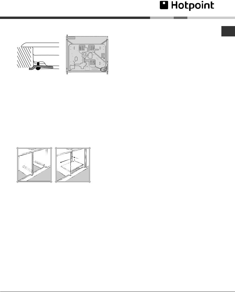
Fitting the appliance
Gas and mixed hobs are manufactured with type X degree protection against overheating. The following precautions must be taken when installing the hob:
•Kitchen cabinets adjacent to the appliance and taller than the top of the hob must be at least 600 mm from the edge of the hob.
•Hoods must be installed according to their relative installation instruction manuals and at a minimum distance of 650 mm from the hob.
•Place the wall cabinets adjacent to the hood at a minimum height of 420 mm from the hob (see figure).
|
600mm min. |
700mmmin. |
600mmmin. |
If the hob is installed beneath a wall cabinet, the latter must be situated at a minimum of 700 mm above the hob (see figure).
•The installation cavity should have the dimensions indicated in the figure. Fastening hooks are provided, allowing you to fasten the hob to tops that are between 20 and 40 mm thick. To ensure the hob is securely fastened to the top, we recommend you use all the
hooks provided.
55 mm
475 mm
555 mm
•Before fastening the cooktop in place, position the seal (supplied) along the perimeter of the countertop, as shown in the figure.
Hook fastening diagram
Hooking position |
Hooking position |
for top H=20 mm |
for top H=30 mm |
|
|
PLEASE PHONE US TO REGISTER YOUR APPLIANCE AND ACTIVATE YOUR PARTS GUARANTEE ON 08448 24 24 24
2
Front
|
|
Back |
|
|
|
|
|
|
|
|
|
Hooking position |
|
||
for top H=40 mm |
|
|
|
! Use the hooks contained in the “accessory pack”
•Where the hob is not installed over a built-in oven, a wooden panel must be installed as insulation. This must be placed at a minimum distance of 20 mm from the lower part of the hob.
Ventilation
To ensure adequate ventilation, the back panel of the cabinet must be removed. It is advisable to install the oven so that it rests on two strips of wood, or on a completely flat surface with an opening of at least 45 x 560 mm (see diagrams).
. |
45 |
mm |
. |
mm |
|
||
560 |
|
|
|
! The hob can only be installed above built-in ovens with a cooling ventilation system.
Gas connection
The appliance should be connected to the main gas |
GB |
|
|
supply or to a gas cylinder in compliance with current |
|
national regulations. Before carrying out the connection, |
|
make sure the cooker is compatible with the gas supply |
|
you wish to use. |
|
! Check that the pressure of the gas supply is consistent |
|
with the values indicated in Table 1 (“Burner and nozzle |
|
specifications”). This will ensure the safe operation and |
|
longevity of your appliance while maintaining efficient |
|
energy consumption. |
|
Connection with a rigid pipe (copper or steel) |
|
! Connection to the gas system must be carried out in |
|
such a way as not to place any strain of any kind on the |
|
appliance. |
|
There is an adjustable L-shaped pipe fitting on the |
|
appliance supply ramp and this is fitted with a seal in |
|
order to prevent leaks. The seal must always be replaced |
|
after rotating the pipe fitting (seal provided with |
|
appliance). The gas supply pipe fitting is a threaded 1/2 |
|
gas cylindrical male attachment. |
|
Connecting a flexible jointless stainless steel pipe to a |
|
threaded attachment |
|
The gas supply pipe fitting is a threaded 1/2 gas |
|
cylindrical male attachment. |
|
These pipes must be installed so that they are never |
|
longer than 2000 mm when fully extended. Once |
|
connection has been carried out, make sure that the |
|
flexible metal pipe does not touch any moving parts and |
|
is not compressed. |
|
! Only use pipes and seals that comply with current |
|
national regulations. |
|
Checking the tightness of the connection |
|
! When the installation process is complete, check the |
|
pipe fittings for leaks using a soapy solution. Never use a |
|
flame. |
|
• Adjusting the burners’ primary air : |
|
Does not require adjusting. |
|
! Should the gas pressure used be different (or vary |
|
slightly) from the recommended pressure, a suitable |
|
pressure regulator must be fitted to the inlet pipe (in order |
|
to comply with current national regulations). |
|
PLEASE PHONE US TO REGISTER YOUR APPLIANCE AND ACTIVATE YOUR PARTS GUARANTEE ON 08448 24 24 24
3
|
|
|
|
|
|
|
|
|
|
|
|
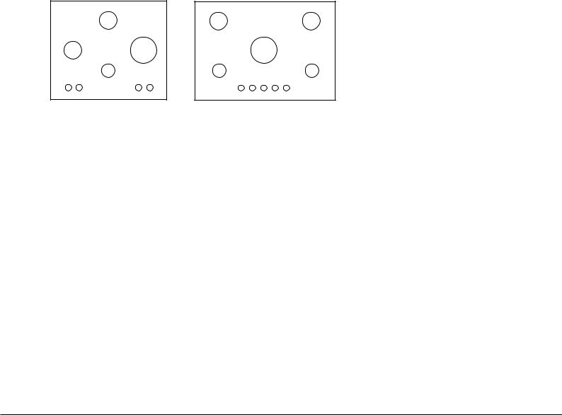
Burner and nozzle specifications |
|
|
|
|
|
||
GB |
|
|
|
|
|
|
|||
|
|
|
|
|
|
|
|
|
|
|
|
Table 1 |
|
|
|
Naturale Gas |
|
||
|
|
|
|
|
|
||||
|
|
|
|
|
|
|
|
|
|
|
|
Burner |
Diameter |
Thermal Power |
Nozzle |
|
Flow* |
|
|
|
|
|
(mm) |
kW (p.c.s.*) |
1/100 |
|
l/h |
|
|
|
|
|
|
|
|
(mm) |
|
|
|
|
|
|
|
Nomin. |
Reduc. |
|
|
|
|
|
|
|
|
|
|
|
|
|
|
|
|
Fast (R) |
157 |
3.00 |
1.00 |
125 |
|
286 |
|
|
|
|
|
|
|
|
|
|
|
|
|
Semi Fast (S) |
132 |
1.90 |
0.80 |
100 |
|
157 |
|
|
|
|
|
|
|
|
|
|
|
|
|
Auxiliary (A) |
110 |
1.00 |
0.50 |
72 |
|
95 |
|
|
|
|
|
|
|
|
|
|
|
|
|
Supply pressures |
Nominal (mbar) |
|
20 |
|
|||
|
|
Minimum (mbar) |
|
17 |
|
||||
|
|
|
Maximum (mbar) |
|
25 |
|
|||
|
|
|
|
|
|
|
|
|
|
*At 15°C and 1013 mbar-dry gas Natural P.C.S. = 37.78 MJ/m³
|
S |
S |
S |
S |
R |
|
R |
|
A |
A |
A |
GX641FGX |
|
GX751FGX |
|
GX641FGK |
|
GX751FGK |
|
PLEASE PHONE US TO REGISTER YOUR APPLIANCE AND ACTIVATE YOUR PARTS GUARANTEE ON 08448 24 24 24
4
 Loading...