


DUI611PX
GB English
Operating Instructions
COOKER AND OVEN
Contents
Operating Instructions,1
Warnings,2
Description of the appliance-Overall view,3 Description of the appliance-Control Panel,4 Installation,5
Start-up and use,7 Cooking modes,8 Precautions and tips,16 Care and maintenance,18
Guarantee ,22

GB Warnings
WARNING: The appliance and its accessible parts become hot during use. Care should be taken to avoid touching heating elements.
Children less than 8 years of age shall be kept away unless continuously supervised. This appliance can be used by children aged from 8 years and above and persons with reduced physical, sensory or mental capabilities or lack of experience and knowledge if they have been given supervision or instruction concerning
use of the appliance in a safe way and understand the hazards involved. Children shall not play with the appliance. Cleaning and user maintenance shall not be made by children without supervision. WARNING: Unattended cooking on a hob with fat or oil can be dangerous and may result in fire.
NEVER try to extinguish a fire with water, but switch off the appliance and then cover flame e.g. with a lid or a fire blanket. Do not use harsh abrasive cleaners or sharp metal scrapers to clean the oven door glass since they can scratch the surface, which may result in shattering of the glass.
The internal surfaces of the compartment (where present) may become hot. Before initiating the automatic cleaning cycle:
•clean the oven door;
•remove large or coarse food residues from the inside of the oven using a damp sponge. Do not use detergents;
•remove all accessories and the sliding rack kit (where present);
•do not place tea towels
Keep children away from the appliance during the automatic cleaning cycle as surfaces may become very hot.
2
2
1 |
|
|
|
|
|
Description of the appliance |
|
|
|
|
|
GB |
|
|
|
|
|
|
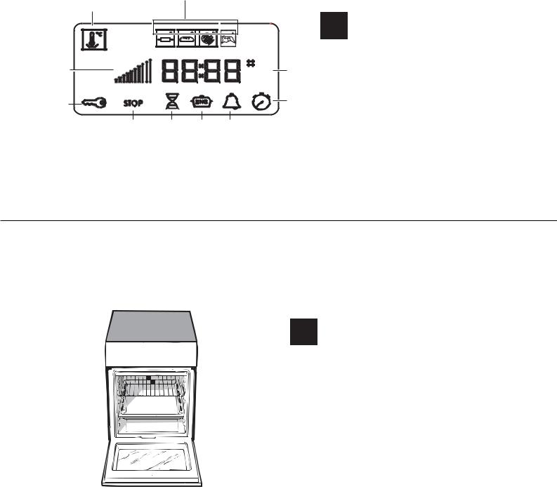
DISPLAY |
|
|
|
|
|
|
|
|
|
|
|
|
|
1. LOW TEMPERATURE MODE icon |
|
3 |
|
|
|
10 |
2. AUTOMATIC COOKING MODE icons |
|
|
|
|
3. Indicator Preheating |
|||
|
|
|
|
|
4. indicator DOOR LOCK |
|
|
|
|
|
|
5. icon STOP |
|
4 |
|
|
|
9 |
6. icon DURATION |
|
|
|
|
7. icon END OF COOKING |
|||
5 |
6 |
7 |
8 |
|
8. icon TIMER |
|
|
9. icon CLOCK |
|||||
|
|
|
|
|
10.digits TIME and TEMPERATURE |
|
1 |
|
|
|
|
|
|
|
|
|
|
|
|
|
|
|
|
|
|
|
|
|
|
|
|
|
|
|
|
|
|
|
|
|
|
|
2 |
|
|
|
|
|
|
6 |
||||||||||
|
|
|
|
|
|
||||||||||||
|
|
|
|
|
|
|
|||||||||||
3 |
|
|
|
|
|
|
|
|
|
|
7 |
||||||
|
|
|
|
|
|
|
|||||||||||
|
|
|
|
|
|
|
|
|
|||||||||
|
|
|
|
|
|
|
|
8 |
|||||||||
|
|
|
|
|
|
|
|||||||||||
4 |
|
|
|
|
|
|
|
|
|
|
|
|
|
|
9 |
||
|
|
|
|
|
|
|
|
|
|
|
|
||||||
|
|
|
|
|
|
|
|
|
|
|
|
|
|
10 |
|||
|
|
|
|
|
|
|
|
|
|
|
|
||||||
5 |
|
|
|
|
|
|
|
|
|
|
11 |
||||||
|
|
|
|
|
|
|
|
|
|||||||||
|
|
|
|
|
|
|
|
5 |
|||||||||
|
|
|
|
|
|
||||||||||||
|
|
|
|
|
|
|
|||||||||||
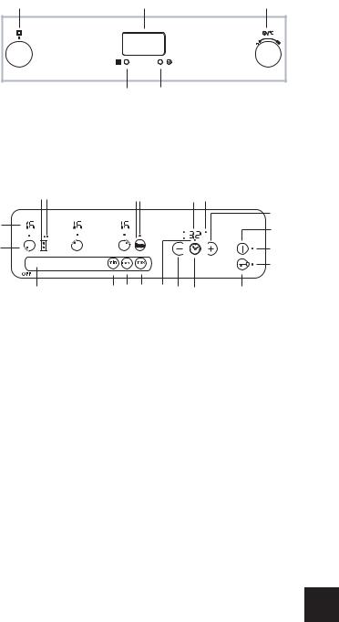
Description of the appliance
GB Overall view
1.Glass ceramic hob
2.Control panel 3..Sliding grill rack 4.DRIPPING pan 5.Adjustable foot
6.GUIDE RAILS for the sliding racks 7.position 5
8.position 4 9.position 3 10.position 2 11.position 1
3
1 |
2 |
3 |
|
4 5
1920 |
|
|
11 12 |
|
|
7 |
8 |
|
|
|
|
|
|
|
17 |
3 |
|
|
|
|
|
|
4 |
|
|
|
|
|
|
|
|
2 |
|
|
|
|
|
|
5 |
|
|
|
|
|
|
|
10 |
1 |
16 |
15 |
14 |
13 |
18 |
6 |
9 |
GB |
Description of the appliance |
|
Control panel |
||
|
||
|
|
The control panel described in this manual is only a representative example: it may not exactly match the panelon your appliance.
1 „SLIDER” ZONE - switches the hotplate on/off or adjusts its power level (see Start-up and use).
2COOKING ZONE indicator represents the corresponding cooking zone.
3POWER indicator provides a visual display for the current heat level.
4ON/OFF button switches the appliance on and off.
5ON/OFF indicator light shows whether the appliance is on or off.
6PROGRAMME TIMER* button controls the cooking programme times (see Start-up and use).
7PROGRAMME TIMER* display shows which programme has been selected (see Start-up and use).
8COOKING ZONE PROGRAMMED* indicator lights show which cooking zones are being used during a cooking programme (see Start-up and use).
9CONTROL PANEL LOCK button prevents accidental changes to the hob settings (see Start-up and use).
10CONTROL PANEL LOCK indicator light shows the control panel has been locked (see Start-up and use).
11BOOSTER* button activates the booster function - 3000 W - of the cooking zone (see Start-up and use).
12BOOSTER* indicator light shows that the booster function has been activated.
*Only available in certain models.
GB |
Description of the appliance |
|
Control panel |
||
|
1.SELECTOR knob
2.DISPLAY
3.THERMOSTAT/TIMER knob
4.PYROLITIC CYCLE button
5.SET TIMER button
13 TIMER* indicator light shows that the timer has been activated
14 MAX BUTTON - switches the cooking zone on at its maximum power level 16 (see Start-up and use).
15 MED BUTTON - switches the cooking zone on at its medium power level 8 (see Start-up and use).
16MIN BUTTON - switches the cooking zone on at its minimum power level 1 (see Start-up and use).
17INCREASE TIME* button increases the cooking duration while the timer is running or while a set programme is underway (see Start-up and use).
18DECREASE TIME* button decreases the cooking duration while the timer is running or while a set programme is underway (see Start-up and use).
19EXTENSO TECHNOLOGY button - activates the
EXTENSO TECHNOLOGY mode
20EXTENSO TECHNOLOGY indicator light shows that the EXTENSO TECHNOLOGY function has been activated
! This product complies with the requirements of the atest European Directive on the limitation of power consumption of the standby mode. If no operations are carried out for a period of 2 minutes, after the residual heat indicator lights turn
off and the fan stops (if present), the appliance automatically switches to the .off mode.. The appliance resumes the operating mode once the ON/OFF button is pressed.
GB Assistance
Warning:
The appliance is fitted with an automatic diagnostic system which detects any malfunctions. Malfunctions are displayed by messages of the following type: “F” followed by numbers.
Call for technical assistance in the event of a malfunction. ! Never use the services of an unauthorised technician.
Please have the following information to hand:
•The type of problem encountered.
•The appliance model (Mod.).
•The serial number (S/N).
The latter two pieces of information can be found on the data plate located on the appliance.
4

Installation
! Please keep this instruction booklet in a safe place for future reference.. Make sure the booklet remains with the appliance if it is sold, given away or moved.
!Please read this manual carefully: it contains important information on installation, operation and safety.
!The appliance must be installed by a qualified professional in accordance with the instructions provided.
!Any necessary adjustment or maintenance must be performed after the cooker has been disconnected from the electricity supply.
Positioning and levelling
! The appliance may be installed alongside any cupboards whose height does not exceed that of the hob surface.
! Make sure that the wall which is in contact with the back of the appliance is made from a nonflammable, heat-resistant material (T 90°C).
To install the appliance correctly:
•Place it in the kitchen, the dining room or the studio flat (not in the bathroom).
•If the top of the hob is higher than the cupboards, the appliance must be installed at least 600 mm away from them.
•If the cooker is installed underneath a wall cabinet, there must be a minimum distance of 420 mm between this cabinet and the top of the hob.
|
|
|
|
This distance should |
|
HOOD |
|
|
|
be increased to 700 |
|
|
|
|
mm if the wall cabinets |
||
|
|
|
|
||
Min. 600mm. |
|
min. 650 mm. with hood |
min. 700 mm. without hood |
are flammable (see |
|
Min. 420mm. |
Min. 420mm. |
figure). |
|||
• Do not position |
|||||
blinds behind the |
|||||
cooker or less than 200 |
|||||
|
|
|
|
||
|
|
|
|
mm away from its |
|
|
|
|
|
sides. |
• Any hoods must be installed in accordance with
the instructions listed in the relevant operating manual.
Levelling
If it is necessary to level the appliance, screw the adjustable feet into the positions provided on each corner of the base of the cooker (see figure).
The legs* fit into the slots on the underside of the base of the cooker.
Electrical connection
GB
Electric cookers come without a power supply cable. The cooker is designed to operate on an electricity supply which conforms to the electrical data shown on the Rating Plate. The cooker can be connected to the mains only after removing the back panel of the terminal board itself with a screwdriver.
! the following installation procedure must be carried out by a qualified electrician. The electrical installation must comply with the IEE Regulations, Building & local By-Lays.
1. Open the terminal board by inserting a screwdriver into the side tabs of the cover. Use the screwdriver as a lever by pushing it down to open the cover (see
diagram).
2. Loosen the cable clamp screw and remove it, using a screwdriver as a lever (see figure).
3. Remove the wire contact screws L-N-  , then fasten the wires under the screw heads, respecting the colour
code: Black/Blue (N), Red/ Brown (L) and Bare Wire/ Yellow-Green ( ).
).
• Once the connections have been made, tighten all the terminal screws fully.
•Fasten the supply cable in place with the clamp and close the cover of the terminal board.
The appliance must not be installed behind
a decorative door in order to avoid overheating
5
Connecting the supply cable to the mains
GB
WARNINGS: THIS APPLIANCE MUST BE EARTHED.
!The cooker must be connected to the mains by a switched (double pole) cooker outlet correctly fused with a capacity appropriate to that shown on the cooker Rating Plate. All electrical wiring from the consumer unit to the cooker, via the switched double pole cooker outlet, must be of an acceptable type and current rating as above.
!the supply cable must be positioned so that it never reaches at any point a temperature 50°C higher than the room temperature. The cable must be routed away from the rear vents.
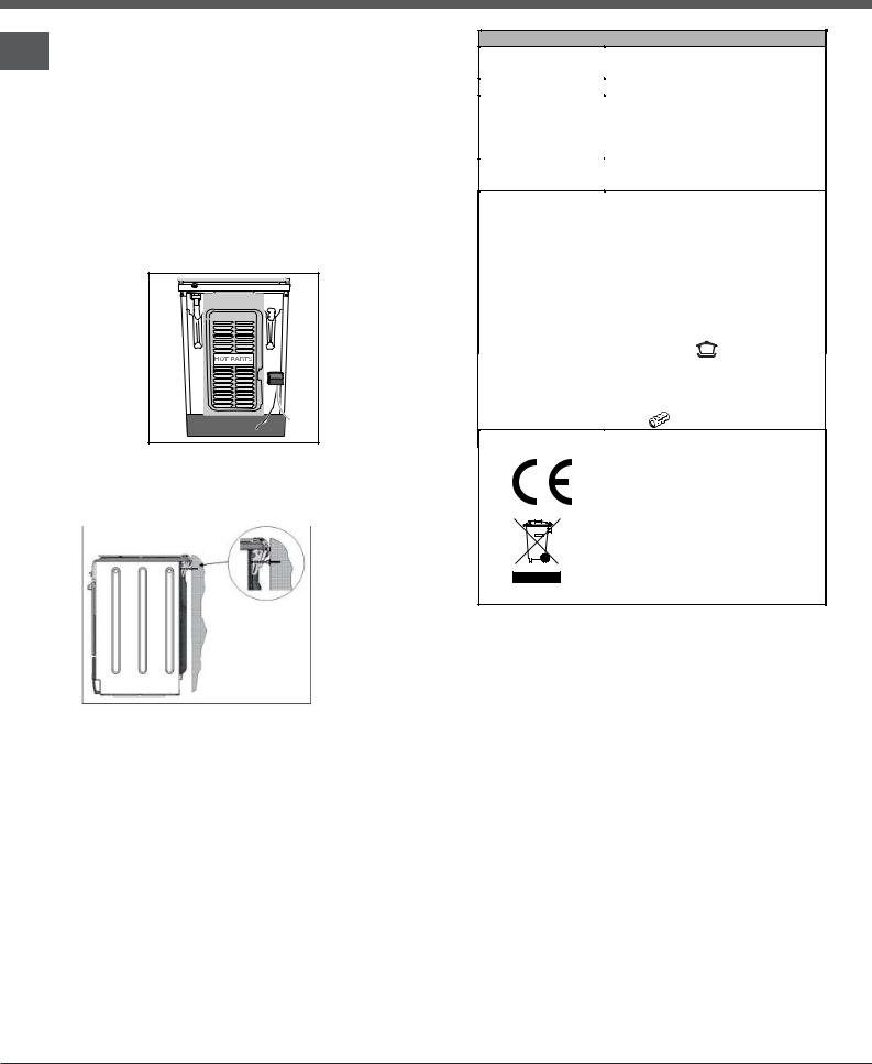
HOT PARTS
Safety Chain
! In order to prevent accidental
tipping of the appliance, for example by a child climbing onto the
oven door, the supplied safety chain MUST be installed!
The cooker is fitted with a safety chain to be fixed by means of a screw (not supplied with the cooker) to the wall behind the appliance, at the same height as the chain is attached to the appliance.
Choose the screw and the screw anchor according to the type of material of the wall behind the appliance. If the head of the screw has a diameter smaller than 9mm, a washer should be used. Concrete wall requires the screw of at least 8mm of diameter, and 60mm of length.
Ensure that the chain is fixed to the rear wall of the cooker and to the wall, as shown in figure, so that after installation it is tensioned and parallel to the
ground level.
TABLE OF CHARACTERISTICS
Oven dimensions
(HxWxD) 34,0x42,4x42,4cm
Volume |
58 l |
|
Useful |
width 42 cm |
|
measurements |
||
depth 44 cm |
||
relating to the oven |
||
height 8.5 cm |
||
compartment |
|
|
Voltage and |
see data plate |
|
frequency |
||
|
ENERGY LABEL
and ECODESIGN
This appliance meets the Eco Design requirements of European Regulations n. 65/2014, and
n.66/2014 in conformity to
the European standard EN 60350-1.
Energy consumption for Natural convection – heating mode:
Convection mode
Declared energy consumption for Forced convection Class – heating mode:
Roasting
6
 Loading...