


DD 642 W/HA(BK)
 Portuges
Instruções para a utilização
PLANO
Índice
Instruções para a utilização,1 Advertências,3 Assistência,4
Descrição do aparelho,5 Instalação,19
Início e utilização,23 Precauções e conselhos,23 Manutenção e cuidados,24 Anomalias e soluções,24
 English
Operating Instructions
HOB
Contents
Operating Instructions,1
Warnings,2
Assistance,4
Description of the appliance,5
Installation,6
Start-up and use,10
Precautions and tips,10
Maintenance and care,11
Troubleshooting,11
 Español
Manual de instrucciones
ENCIMERA
Sumario
Manual de instrucciones,1
Advertencias,2
Asistencia,4
Descripción del aparato,5
Instalación,12
Puesta en funcionamiento y uso,16
Precauciones y consejos,16
Mantenimiento y cuidados,17
Anomalías y soluciones,17

|
|
|
|
|
|
|
|
|
|
|
|
|
|
|
|
|
|
Warnings |
Advertencias |
||||
WARNING: The appliance and its accessible parts become hot during use. Care should be taken to avoid touching heating elements. Children less than 8 years of age shall be kept away unless continuously supervised. This appliance can be used by children aged from 8 years and above and persons with reduced physical, sensory or mental capabilities or lack of experience and knowledge if they have been given supervision or instruction concerning use of the appliance in a safe way and understand the hazards involved. Children shall not play with the appliance. Cleaning and user maintenance shall not be made by children without supervision.
WARNING: Unattended cooking on a hob with fat or oilcanbedangerousandmayresultinfire.NEVER try to extinguish a fire with water, but switch off the appliance and then cover flame e.g. with a lid or a fire blanket.
WARNING:Dangeroffire:donotstoreitemsonthe cooking surfaces.
Never use steam cleaners or pressure cleaners on the appliance.
Remove any liquid from the lid before opening it. Do not close the glass cover (if present) when the gas burners or electric hotplates are still hot.
The appliance is not intended to be operated by means of an external timer or separate remote control system.
CAUTION: the use of inappropriate hob guards can cause accidents.
CAUTION: In case of hotplate glass breakage:
-shut immediately off all burners and any electrical heating element and isolate the appliance from the power supply
-do not touch the appliance surface
ATENCIÓN:Esteaparatoysuspartesaccesiblesse vuelven muy calientes durante el uso. Por lo tanto, es importante evitar tocar los elementos calentadores. Mantenga alejados a los niños menores de 8 años si nosoncontinuamentevigilados. Elpresenteaparato puede ser utilizado por niños mayores de 8 años y por personas con capacidades físicas, sensoriales o mentales disminuidas o sin experiencia ni conocimientos, si se encuentran bajo una adecuada vigilancia o si han sido instruidos sobre el uso del aparato de modo seguro y comprenden los peligros relacionados con el mismo. Los niños no deben jugar con el aparato. Las operaciones de limpieza y de mantenimiento no deben ser realizadas por niños sin vigilancia.
ATENCIÓN:Dejarunquemadorcongrasasoaceites sin vigilancia puede ser peligroso y provocar un incendio. NUNCAintente apagar una llama/incendio con agua, se debe apagar el aparato y cubrir la llama, por ejemplo, con una tapa o con una manta ignífuga.
ATENCIÓN: Riesgo de incendio: no deje objetos sobre las superficies de cocción.
No utilice nunca limpiadores a vapor o de alta presión para la limpieza del aparato.
Elimineeventualeslíquidospresentessobrelatapa antes de abrirla. No cierre la tapa de vidrio (si existe) cuando los quemadores o la placa eléctrica todavía están calientes.
El aparato no se debe poner en funcionamiento a través de un temporizador externo o de un sistema de mando a distancia.
2

ATENCIÓN: el uso de protecciones inapropiadas de la placa de cocción puede provocar accidentes.
ATENCIÓN: Si se dañara la superficie de vidrio:
-apague inmediatamente todos los quemadores y eventuales elementos calentadores eléctricos y desconecte el aparato de la red eléctrica.
-no toque la superficie del aparato.
Advertências
ATENÇÃO: Este aparelho e as suas partes acessíveis aquecem muito durante a utilização. É preciso ter atenção e evitar tocar os elementos que aquecem. Manter afastadas as crianças com menos de 8 anos, caso não estejam a ser vigiadas. O presente aparelho pode ser utilizado por crianças com mais de 8 anos e por pessoas com capacidades físicas, sensoriais ou mentais reduzidas ou com pouca experiência e conhecimentos, caso sejam adequadamente vigiadas ou caso tenham recebido instruções em relação ao uso do aparelho de forma segura e tenham conhecimento dos perigos associados. As crianças não devem brincar com o aparelho. As operações de limpeza e manutenção não devem ser efectuadas por crianças sem vigilância.
ATENÇÃO:Deixarumfogãocomgorduraeóleosem vigilância pode ser perigoso e provocar um incêndio. NUNCA tente apagar as chamas com água. É necessário desligar o aparelho e cobrir as chamas com uma tampa ou com uma manta ignífuga.
ATENÇÃO: Risco de incêndio: não deixe objectos sobre as superfícies de cozedura.
Nunca utilize equipamento de limpeza a vapor ou de alta pressão para limpar o aparelho.
Elimine os líquidos presentes na tampa antes de abri-la. Não feche a tampa de vidro (se presente) se os queimadores ou a chapa eléctrica ainda estiverem quentes.
O aparelho não é destinado a ser colocado em funcionamento por meio de um temporizador externo ouporumsistemadecomandoàdistânciaseparado.
ATENÇÃO: O uso de protecções do plano inadequadas pode causar incidentes.
ATENÇÃO: Em caso de danos do plano em vidro:
-Desligue imediatamente todos os queimadores e eventuais elementos de aquecimento eléctricos e desligue o aparelho da rede eléctrica.
-Não toque na superfície do aparelho.
3
Assistance
Communicating:
•the type of problem encountered.
•appliance model (Mod.)
•serial number (S/N)
This information is found on the data plate located on the appliance and/or on the packaging.
Asistencia
Comunique:
•el tipo de anomalía
•el modelo de la máquina (Mod.)
•el número de serie (S/N)
Esta información se encuentra en la placa de características ubicada en el aparato y/o en el embalaje.
La siguiente información es válida solo para España.
Para otros países de habla hispana consulte a su vendedor.
Ampliación de garantía
Llame al 902.363.539 y le informaremos sobre el fantástico plan de ampliación de garantía hasta 5 años.
Consiga una cobertura total adicional de
•Piezas y componentes
•Mano de obra de los técnicos
•Desplazamiento a su domicilio de los técnicos
Y NO PAGUE AVERIAS NUNCA MAS
Servicio de asistencia técnica (SAT)
Llame al 902.133.133 y nuestros técnicos intervendrán con rapidez y eficacia, devolviendo el electrodoméstico a sus condiciones óptimas de funcionamiento.
En el SAT encontrará recambios, accesorios y productos específicos para la limpieza y mantenimiento de su electrodoméstico a precios competitivos.
ESTAMOS A SU SERVICIO
Assistência
Comunique:
•o tipo de avaria
•o modelo da máquina (Mod.)
•o número de série (S/N)
Estas últimas informações encontram-se na placa de identificação situada no aparelho e/ou na embalagem.
4
|
|
|
|
|
|
|
|
|
|
|
|
|
|
|
|
|
|
|
|
|
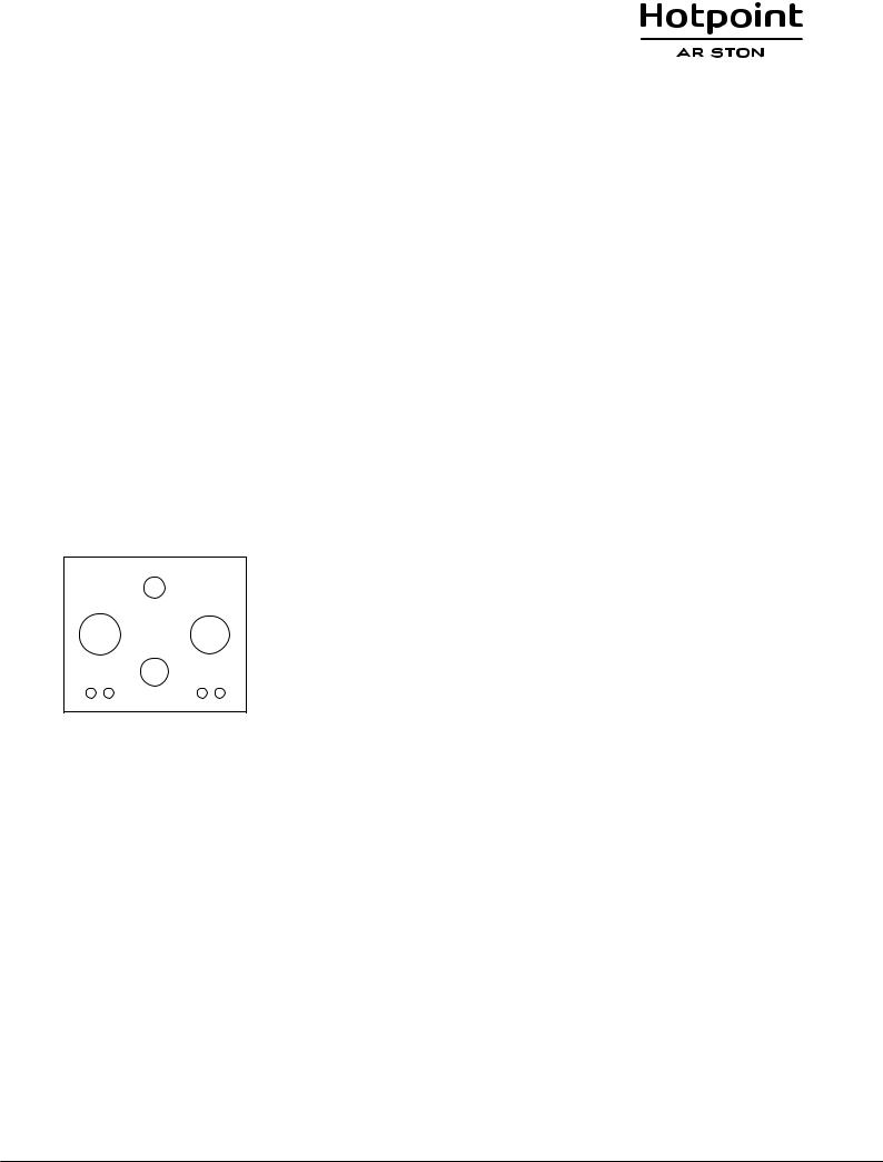
Description of the appliance |
Descrição do aparelho |
|||||
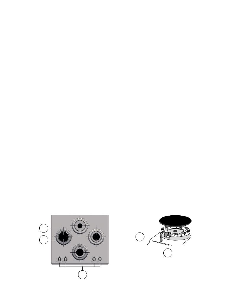
Overall view |
Vista de conjunto |
|||||
1. |
Support Grid for COOKWARE |
1. |
Grades de suporte para RECIPIENTES DE COZEDURA |
|||
2. |
GAS BURNERS |
2. |
QUEIMADORES A GÁS |
|||
3. |
Control Knobs for GAS BURNERS |
3. |
Selectores de comando dos QUEIMADORES A GÁS |
|||
4. |
Ignition for GAS BURNERS |
4. |
Vela para acender osQUEIMADORES A GÁS |
|||
5. |
SAFETY DEVICES |
5. |
DISPOSITIVO DE SEGURANÇA |
|||
• |
GASBURNERSdiffer in size and power. Use the diameter of the cookware |
• |
Os QUEIMADORES sãodediferentestamanhosepotências.Escolhao |
|||
|
to choose the most appropriate burner to cook with. |
|
mais adequado ao diâmetro do recipiente a ser utilizado. |
|||
• |
Control Knobs for GAS BURNERS adjust the size of the flame. |
• |
Selectores de comando dos QUEIMADORES A GÁS para a regulação |
|||
• |
GAS BURNER IGNITION enablesaspecificburnertobelitautomatically. |
|
da chama. |
|||
• |
SAFETY DEVICE stops the gas flow if the flame is accidentally |
• |
Vela para acender osQUEIMADORES A GÁS permite o acendimento |
|||
|
extinguished. |
|
automático do queimador escolhido. |
|||
|
|
|
• |
DISPOSITIVO DE SEGURANÇA no caso em que a chama se apague |
||
|
|
|
|
acidentalmente, interrompe a saída do gás. |
||
|
|
|
|
|||
|
|
|
|
|
|
|
Descripción del aparato
Vista en conjunto
1.Parrillas de apoyo para RECIPIENTES DE COCCIÓN
2.QUEMADORES A GAS
3.Mandos de los QUEMADORES A GAS
4.Bujía de encendido de los QUEMADORES A GAS
5.DISPOSITIVO DE SEGURIDAD
•QUEMADORES A GAS: sondedistintasdimensionesypotencias.Elija siempre el más adecuado para el diámetro del recipiente que va a utilizar.
•Mandos de los QUEMADORES A GAS para la regulación de la llama.
•Bujía de encendido de los QUEMADORESAGAS: permite el encendido automático del quemador.
•DISPOSITIVO DE SEGURIDAD: si se apaga accidentalmente la llama, interrumpe la salida de gas.
1 |
|
2 |
5 |
|
4
3
5

GB Installation
!Before operating your new appliance please read this instruction booklet carefully. It contains important information for safe use, installation and care of the appliance.
!Please keep these operating instructions for future reference. Pass them on to possible new owners of the appliance.
Positioning
!Keep packaging material out of the reach of children. It can become a choking or suffocation hazard (see Precautions and tips).
!Theappliancemustbeinstalledbyaqualifiedprofessionalaccordingtothe instructions provided. Incorrect installation may cause harm to people and animals or may damage property.
!This unit may be installed and used only in permanently ventilated rooms in accordance with current national regulations. The following requirements must be observed:
• The room must be equipped with an air extraction system that expels any combustion fumes. This may consist of a hood or an electric fan that automatically starts each time the appliance is switched on.
|
|
|
|
|
|
|
|
|
|
|
|
|
|
|
|
|
|
|
|
|
|
|
|
|
|
|
|
|
|
|
|
|
|
|
|
|
|
|
|
|
|
|
|
|
|
|
|
|
|
|
|
|
|
|
|
|
|
|
|
|
|
|
|
|
|
|
|
|
|
|
|
|
|
|
|
|
|
|
|
|
|
|
|
|
|
|
|
|
|
|
|
|
|
|
|
|
|
|
|
|
|
|
|
|
|
|
|
|
|
|
|
|
|
|
|
|
|
|
|
|
|
|
|
|
|
|
|
|
|
|
|
|
|
|
|
|
|
|
|
|
|
|
|
|
|
|
|
|
|
|
|
|
In a chimney stack or branched flue. |
Directly to |
|
|
|
|
|||||||||||
(exclusively for cooking appliances) |
the Outside |
|
|
|
|
|||||||||||
•The room must also allow proper air circulation, as air is needed for combustiontooccurnormally.Theflowofairmustnotbelessthan2m3/h per kW of installed power.
|
The air circulation system may take air directly |
|
from the outside by means of a pipe with an |
|
inner cross section of at least 100 cm2; the |
|
opening must not be vulnerable to any type |
A |
of blockages. |
Examples of ventilation holes for comburant air.
Adjacent |
Room to be |
Room |
Vented |
Enlarging the ventilation slot |
|
between window and floor. |
|
The system can also provide the air needed for combustion indirectly, i.e. from adjacent rooms fitted with air circulation tubes as described above. However, these rooms must not be communal rooms, bedrooms or rooms that may present a fire hazard.
•Intensive and prolonged use of the appliance may necessitate supplemental ventilation, e.g. opening a window or increasing the power of the air intake system (if present).
•Liquidpetroleumgassinkstothefloorasitisheavierthanair.Therefore, rooms containing LPG cylinders must also be equipped with vents to allow gas to escape in the event of a leak. As a result LPG cylinders, whether partially or completely full, must not be installed or stored in rooms or storage areas that are below ground level (cellars, etc.). It is advisable to keep only the cylinder being used in the room, positioned so that it is not subject to heat produced by external sources (ovens, fireplaces, stoves, etc. ) which could raise the temperature of the cylinder above 50°C.
Fitting the appliance
The following precautions must be taken when installing the hob:
•Kitchen cabinets adjacent to the appliance and taller than the top of the hob must be at least 200 mm from the edge of the hob.
•Hoods must be installed according to their relative installation instruction manualsandataminimumdistanceof650mmfromthehob(seefigure).
•Place the wall cabinets adjacent to the hood at a minimum height of 420 mm from the hob (see figure).
|
|
|
|
|
|
|
|
|
|
If the hob is installed beneath a wall cabinet, |
|
|
|
|
|
|
|
|
|
|
|
|
|
|
|
|
|
|
|
|
|
the latter must be situated at a minimum of 700 |
|
|
|
|
|
|
|
|
|||
|
|
|
|
|
|
|
420mm min. |
|
|
mm above the hob. |
650mm min. |
|
600mm min. |
|
|
|
|||||
|
|
|
||||||||
|
|
|||||||||
|
|
|
|
|
||||||
|
|
|
|
|
|
|
|
|||
|
|
|
|
|
|
|
|
|
|
|
|
|
|
|
|
|
|
|
|
|
|
|
|
|
|
|
|
|
|
|
|
|
|
|
|
|
|
|
|
|
|
|
|
•Theinstallationcavityshouldhavethedimensionsindicatedinthefigure.
Fastening hooks are provided, allowing you to fasten the hob to tops that are between 20 and 40 mm thick. To ensure the hob is securely fastened to the top, we recommend you use all the hooks provided.
|
|
|
555 mm |
|
|
|
|
|
|
55 |
mm |
|
|
mm |
|
|
|||
|
|
|
||
|
|
475 |
||
|
|
|
||
|
|
|
|
|
•Before fastening the cooktop in place, position the seal (supplied) along the perimeter of the countertop, as shown in the figure.
Hook fastening diagram
Hooking position for top H=20mm Hooking position for top H=30mm
Front
Hooking position for top H=40mm Back
! Use the hooks contained in the “accessory pack”.
6
•Where the hob is not installed over a built-in oven, a wooden panel must be installed as insulation. This must be placed at a minimum distance of 20 mm from the lower part of the hob.
Ventilation
To ensure adequate ventilation, the back panel of the cabinet must be removed. It is advisable to install the oven so that it rests on two strips of wood, or on a completely flat surface with an opening of at least 45 x 560 mm (see diagrams).
. |
45 |
mm. |
mm |
|
|
560 |
|
|
! The hob can only be installed above built-in ovens with a cooling ventilation system.
Electrical connection
Hobs equipped with a three-pole power supply cable are designed to operate with alternating current at the voltage and frequency indicated on the data plate (this is located on the lower part of the appliance). The earth wire in the cable has a green and yellow cover. If the appliance is to be installed above a built-in electric oven, the electrical connection of the hob and the oven must be carried out separately, both for electrical safety purposes and to make extracting the oven easier.
Connecting the supply cable to the mains
Install a standardised plug corresponding to the load indicated on the data plate.
The appliance must be directly connected to the mains using an omnipolar circuit-breaker with a minimum contact opening of 3 mm installed between the appliance and the mains. The circuit-breaker must be suitable for the charge indicated and must comply with current electrical regulations (the earthing wire must not be interrupted by the circuit-breaker). The supply cable must not come into contact with surfaces with temperatures higher than 50°C.
! The installer must ensure that the correct electrical connection has been made and that it is compliant with safety regulations.
Before connecting to the power supply, make sure that:
•the appliance is earthed and the plug is compliant with the law.
•the socket can withstand the maximum power of the appliance, which is indicated on the data plate.
•the voltage is in the range between the values indicated on the data plate.
•the socket is compatible with the plug of the appliance. If the socket is incompatible with the plug, ask an authorised technician to replace it. Do not use extension cords or multiple sockets.
!Once the appliance has been installed, the power supply cable and the electrical socket must be easily accessible.
!The cable must not be bent or compressed.
!The cable must be checked regularly and replaced by authorised technicians only (see Assistance).
! The manufacturer declines any liability should these safety measures not |
GB |
be observed. |
Gas connection
The appliance should be connected to the main gas supply or to a gas cylinder in compliance with current national regulations. Before carrying out the connection, make sure the cooker is compatible with the gas supply you wish to use. If this is not the case, follow the instructions indicated in the paragraph “Adapting to different types of gas.”
When using liquid gas from a cylinder, install a pressure regulator which complies with current national regulations.
! Check that the pressure of the gas supply is consistent with the values indicatedinTable1(“Burnerandnozzlespecifications”).Thiswillensurethe safe operation and longevity of your appliance while maintaining efficient energy consumption.
Connection with a rigid pipe (copper or steel)
! Connection to the gas system must be carried out in such a way as not to place any strain of any kind on the appliance.
There is an adjustable L-shaped pipe fitting on the appliance supply ramp and this is fitted with a seal in order to prevent leaks. The seal must always be replaced after rotating the pipe fitting (seal provided with appliance).The gas supply pipe fitting is a threaded 1/2 gas cylindrical male attachment.
Connecting a flexible jointless stainless steel pipe to a threaded attachment
Thegassupplypipefittingisathreaded1/2gascylindricalmaleattachment.
These pipes must be installed so that they are never longer than 2000 mm when fully extended. Once connection has been carried out, make sure that theflexiblemetalpipedoesnottouchanymovingpartsandisnotcompressed.
! Only use pipes and seals that comply with current national regulations.
Checking the tightness of the connection
! When the installation process is complete, check the pipe fittings for leaks using a soapy solution. Never use a flame.
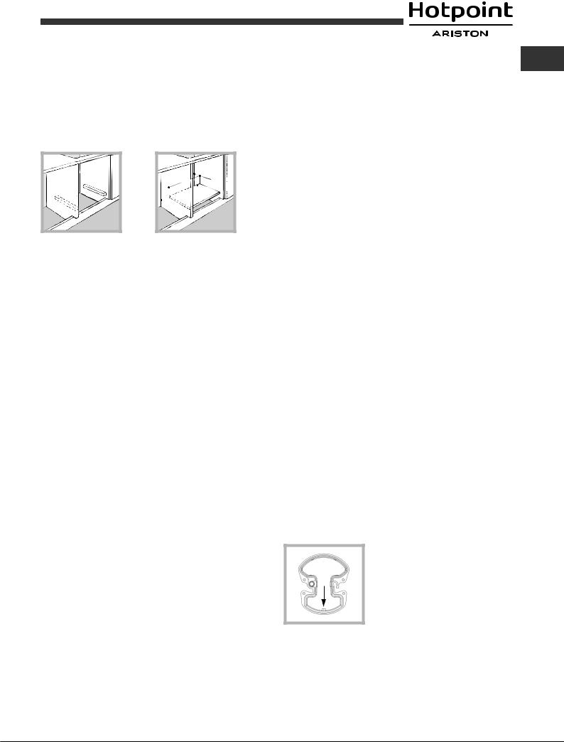
Adapting to different types of gas
To adapt the hob to a different type of gas other than default type (indicated on the rating plate at the base of the hob or on the packaging), the burner nozzles should be replaced as follows:
1.Remove the hob grids and slide the burners off their seats.
2.Unscrew the nozzles using a 7 mm socket spanner, and replace them with nozzles for the new type of gas (see table 1 “Burner and nozzle characteristics”).
In the case of the Mini WOK burner, use a spanner with a 7 mm opening to unscrew the nozzle (see figure).
3.Reassemble the parts following the above procedure in the reverse order.
4.Once this procedure is finished, replace the old rating sticker with one indicating the new type of gas used. Sticker are available from any of our Service Centres.
• Adjusting the burners’ primary air Does not require adjusting.
7
|
|
|
|
|
|
|
|
|
|
|
|
|
|
|
|
|
|
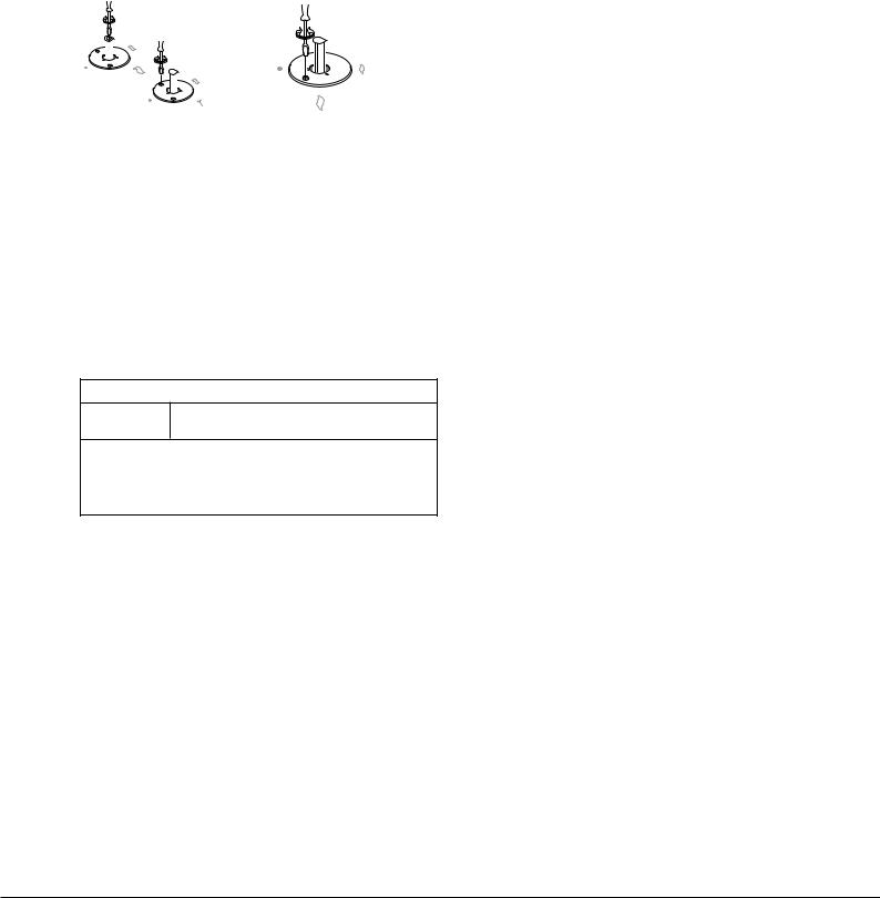
• |
Setting the burners to minimum |
||||||||||||||
GB |
||||||||||||||||
1. |
Turn the tap to the low flame position; |
|||||||||||||||
|
2. |
Remove the knob and adjust the adjustment screw, which is positioned |
||||||||||||||
|
||||||||||||||||
|
|
|
in or next to the tap pin, until the flame is small but steady. |
|||||||||||||
|
3. |
Having adjusted the flame to the required low setting, while theburneris |
||||||||||||||
|
|
|
alight, quickly change the position of the knob from minimum to maximum |
|||||||||||||
|
|
|
and vice versa several times, checking that the flame does not go out. |
|||||||||||||
|
4. |
Someapplianceshaveasafetydevice(thermocouple)fitted.Ifthedevice |
||||||||||||||
|
|
|
fails to work when the burners are set to the low flame setting, increase |
|||||||||||||
|
|
|
this low flame setting using the adjusting screw. |
|||||||||||||
|
|
|
|
|
|
|
|
|
|
|
|
|
|
|
|
|
|
|
|
|
|
|
|
|
|
|
|
|
|
|
|
|
|
|
|
|
|
|
|
|
|
|
|
|
|
|
|
|
|
|
|
|
|
|
|
|
|
|
|
|
|
|
|
|
|
|
|
|
|
|
|
|
|
|
|
|
|
|
|
|
|
|
|
|
|
|
|
|
|
|
|
|
|
|
|
|
|
|
|
|
|
5.Once the adjustment has been made, replace the seals on the by-passes using sealing wax or a similar substance.
!If the appliance is connected to liquid gas, the regulation screw must be fastened as tightly as possible.
!Once this procedure is finished, replace the old rating sticker with one indicating the new type of gas used. Stickers are available from any of our Service Centres.
!Should the gas pressure used be different (or vary slightly) from the recommended pressure, a suitable pressure regulator must be fitted to the inlet pipe (in order to comply with current national regulations).
DATA PLATE
Electrical |
see data plate |
connections |
ECODESIGN
This appliance conforms to the EU Regulation no. 66/2014 implementing Directive 2009/125/EC.
standard EN 30-2-1
8
|
|
|
|
|
|
|
|
|
|
|
|
|
|
|
|
Burner and nozzle specifications |
|
|
|
|
|
|
|
|
|
|
|
||||
|
|
|
|
|
|
|
|
|
|
|
|||||
|
|
|
|
|
|
|
|
|
|
|
|||||
|
|
|
|
|
|
|
|
|
|
GB |
|||||
|
|
|
|
|
|
|
|
|
|
|
|
|
|
|
|
Table 1 |
|
|
|
|
|
Liquid Gas |
|
|
Natural Gas |
|
|||||
|
|
|
|
|
|
|
|
|
|
|
|
||||
Burner |
Diameter |
Thermal Power |
By-pass |
Nozzle |
Flow* |
Nozzle |
|
Flow* |
|
||||||
|
(mm) |
kW (p.c.s.*) |
1/100 |
1/100 |
g/h |
|
|
1/100 |
|
l/h |
|
||||
|
|
Nomin. |
|
Reduc. |
(mm) |
(mm) |
*** |
|
** |
|
(mm) |
|
|
|
|
|
|
|
|
|
|
|
|
|
|||||||
|
|
|
|
|
|
|
|
|
|
|
|
||||
|
|
|
|
|
|
|
|
|
|
|
|
|
|
|
|
Reduced Rapid (RR) |
100 |
2.60 |
|
0.70 |
39 |
80 |
189 |
|
186 |
110(Y) |
|
248 |
|
|
|
|
|
|
|
|
|
|
|
|
|
|
|
|
|
|
|
Semi Rapid (S) |
75 |
1.65 |
|
0.40 |
28 |
64 |
120 |
|
118 |
96(Z) |
|
157 |
|
|
|
|
|
|
|
|
|
|
|
|
|
|
|
|
|
|
|
Auxiliary (A) |
55 |
1.00 |
|
0.40 |
28 |
50 |
73 |
|
71 |
|
79(6) |
|
95 |
|
|
|
|
|
|
|
|
|
|
|
|
|
|
|
|
|
|
Mini WOK (MW) |
110 |
3.50 |
|
1.30 |
61 |
91 |
254 |
|
250 |
138(H) |
|
333 |
|
|
|
|
|
|
|
|
|
|
|
|
|
|
|
|
|
|
|
Supply pressures |
|
Nominal (mbar) |
|
28-30 |
|
37 |
|
20 |
|
|
|||||
|
|
Minimum (mbar) |
|
20 |
|
25 |
|
17 |
|
|
|||||
|
|
Maximum (mbar) |
|
35 |
|
45 |
|
25 |
|
|
|||||
|
|
|
|
|
|
|
|
|
|
|
|
|
|
|
|
*At 15°C and 1013,25 mbar - dry gas
** |
Propane |
P.C.S. = 50.37 MJ/Kg |
*** |
Butane |
P.C.S. = 49.47 MJ/Kg |
|
Natural |
P.C.S. = 37.78 MJ/m3 |
A
RR MW
S
DD 642 W/HA(BK)
9
 Loading...