


KM-650MAH
Table of contents
 Loading...
Hoshizaki
“A Superior Degree
of Reliability”
www.hoshizaki.com
Models
KM-650MAH
KM-650MWH
KM-650MRH
Modular Crescent Cuber
Hoshizaki America, Inc.
SERVICE MANUAL
™
Number: 73147
Issued: 12-12-2006
1

IMPORTANT
Only qualified service technicians should attempt to service or maintain this
unit. No such service or maintenance should be undertaken until the technician
has thoroughly read this Service Manual.
HOSHIZAKI provides this manual primarily to assist qualified service technicians in the
service and maintenance of the unit.
Should the reader have any questions or concerns which have not been satisfactorily
addressed, please call, write or send an e-mail message to the HOSHIZAKI Technical
Support Department for assistance.
HOSHIZAKI AMERICA, INC.
618 Highway 74 South
Peachtree City, GA 30269
Attn: HOSHIZAKI Technical Support Department
Phone: 1-800-233-1940 Technical Service
(770) 487-2331
Fax: 1-800-843-1056
(770) 487-3360
E-mail: techsupport@hoshizaki.com
Web Site: www.hoshizaki.com
NOTE: To expedite assistance, all correspondence/communication MUST include the
following information:
• Model Number
• Serial Number
• Complete and detailed explanation of the problem
2

Please review this manual. It should be read carefully before the icemaker is serviced or
maintenance operations are performed. Only qualified service technicians should service
and maintain the icemaker. This manual should be made available to the technician prior to
service or maintenance.
CONTENTS
I. Specifications ...................................................................................................................... 5
A. Icemaker ....................................................................................................................... 5
1. KM-650MAH (air-cooled) ......................................................................................... 5
2. KM-650MWH (water-cooled) ................................................................................... 6
3. KM-650MRH (remote air-cooled) ............................................................................ 7
B. Condensing Unit ............................................................................................................ 8
1. URC-5F ................................................................................................................... 8
II. General Information ......................................................................................................... 10
A. Construction ................................................................................................................ 10
1. KM-650MAH (air-cooled) .......................................................................................
2. KM-650MWH (water-cooled) ................................................................................. 11
3. KM-650MRH (remote air-cooled) .......................................................................... 12
B. Sequence of Operation ............................................................................................... 13
1. One Minute Fill Cycle ............................................................................................ 13
2. Initial Harvest Cycle .............................................................................................. 13
3. Freeze Cycle ......................................................................................................... 13
4. Pump-Out Cycle ................................................................................................... 13
5. Normal Harvest Cycle .......................................................................................... 13
C. Control Board .............................................................................................................. 15
1. Control Board Layout ............................................................................................. 16
2. Features ................................................................................................................ 17
a) Maximum Water Supply Period – 6 minutes ....................................................... 17
b) Harvest Backup Timer and Freeze Timer ........................................................... 17
c) High Temperature Safety .................................................................................... 17
d) Low Water Safety ............................................................................................... 17
e) High Voltage and Low Voltage Cut-outs ............................................................. 17
f) LED Lights and Audible Alarm Safeties ............................................................... 18
3. Controls and Adjustments ..................................................................................... 19
a) Default Dip Switch Settings ................................................................................ 19
b) Harvest Control – Thermistor ............................................................................. 19
c) Harvest Timer (dip switch 1 & 2) ......................................................................... 20
d) Pump-Out Timer (dip switch 3 & 4)..................................................................... 20
e) Pump-Out Frequency Control (dip switch 5 & 6) ................................................ 21
f) Freeze Timer (dip switch 9 & 10) ......................................................................... 21
g) Bin Control .......................................................................................................... 21
4. Control Board Check Procedure ............................................................................ 22
5. Control Board Replacement .................................................................................. 22
10
3

III. Technical Information ...................................................................................................... 23
A. Water Circuit and Refrigeration Circuit ........................................................................ 23
1. KM-650MAH (air-cooled) .......................................................................................
2. KM-650MWH (water-cooled) ................................................................................. 24
3. KM-650MRH (remote air-cooled) .......................................................................... 25
B. Wiring Diagrams .......................................................................................................... 26
1. KM-650MAH (air-cooled) and KM-650MWH (water-cooled) .................................
2. KM-650MRH (remote air-cooled) ..........................................................................
C. Performance Data ....................................................................................................... 28
1. KM-650MAH (air-cooled) ....................................................................................... 28
2. KM-650MWH (water-cooled) ................................................................................. 29
3. KM-650MRH (remote air-cooled) .......................................................................... 30
IV. Service Diagnosis ........................................................................................................... 31
A. 10-Minute KM Diagnostic Procedure ......................................................................... 31
B. Diagnostic Charts ........................................................................................................ 32
1. No Ice Production .................................................................................................. 32
2. Evaporator is Frozen Up ........................................................................................ 36
3. Low Ice Production ................................................................................................ 37
4. Abnormal Ice ......................................................................................................... 37
5. Other ...................................................................................................................... 37
V. Removal and Replacement of Components .................................................................... 39
A. Service for Refrigerant Lines ...................................................................................... 39
1. Refrigerant Recovery ............................................................................................. 39
2. Evacuation and Recharge (R-404A) ...................................................................... 39
B. Brazing ........................................................................................................................ 40
C. Removal and Replacement of Compressor ................................................................ 40
D. Removal and Replacement of Drier ............................................................................ 41
E. Removal and Replacement of Expansion Valve .......................................................... 42
F. Removal and Replacement of Hot Gas Valve and Line Valve ..................................... 43
G. Removal and Replacement of Evaporator .................................................................. 44
H. Removal and Replacement of Water Regulating Valve - Water Cooled Model Only ... 44
I. Adjustment of Water Regulating Valve - Water-Cooled Model Only ............................. 45
J. Removal and Replacement of Headmaster (Condensing Pressure Regulator - C.P.R.)
- Remote Air-Cooled Model Only .............................................................................. 46
K. Removal and Replacement of Thermistor ................................................................... 47
L. Removal and Replacement of Fan Motor .................................................................... 47
M. Removal and Replacement of Inlet Water Valve ......................................................... 48
N. Removal and Replacement of Pump Motor ................................................................ 48
O. Removal and Replacement of Spray Tubes ................................................................ 49
VI. Cleaning and Maintenance Instructions ......................................................................... 50
A. Cleaning and Sanitizing Procedures ........................................................................... 50
1. Cleaning Procedure ...............................................................................................
2. Sanitizing Procedure - Following Cleaning Procedure ..........................................
B. Maintenance ................................................................................................................ 52
C. Preparing the Icemaker for Long Storage ................................................................... 53
23
26
27
51
52
4
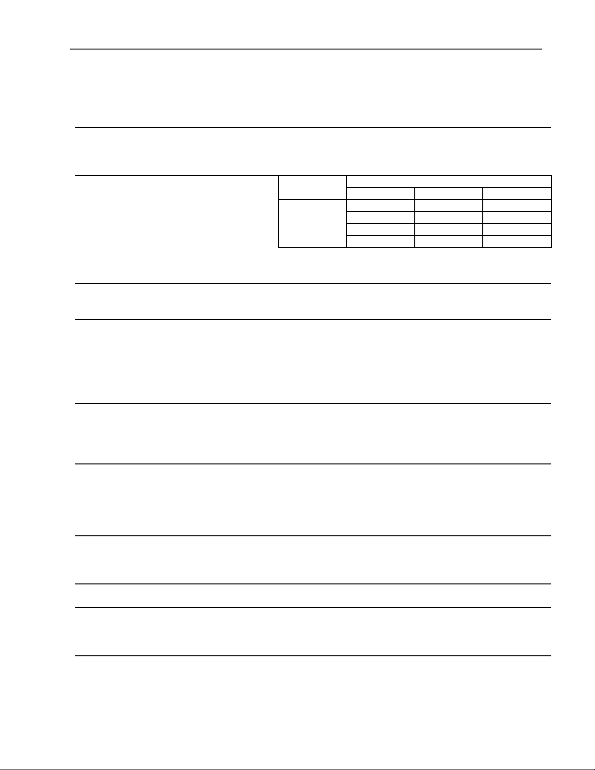
I. Specifications
SPECIFICATION NO. 06A019 ISSUED: 10/10/2006
ITEM: HOSHIZAKI MODULAR CRESCENT CUBER
MODEL: KM-650MAH
AC SUPPLY VOLTAGE 208-230/60/1 (3 wire with neutral for 115V)
AMPERAGE 6.6 A ( 5 Min. Freeze AT 104°F / WT 80°F)
MINIMUM CIRCUIT AMPACITY 15 A
MAXIMUM FUSE SIZE 15 A
APPROXIMATE ICE PRODUCTION Ambient WATER TEMP. (°F)
PER 24 HR. Temp.(°F) 50 70 90
lbs./day ( kg/day ) 70 *589 (267) 566 (257) 526 (238)
Reference without *marks 80 572 (259) 537 (243) 490 (222)
90 566 (257) *512 (232) 467 (212)
100 555 (252) 501 (227) 426 (193)
SHAPE OF ICE Crescent Cube
ICE PRODUCTION PER CYCLE 13.5 lbs. (6.1 kg) 720 pcs.
APPROXIMATE STORAGE CAPACITY N/A
ELECTRIC & WATER CONSUMPTION 90/70°F 70/50°F
ELECTRIC W (kWH/100 lbs.) 1240(5.8) 1100(4.5)
WATER gal./24HR (gal./100 lbs.) 108(21.1) 257(43.7)
EXTERIOR DIMENSIONS (WxDxH) 22" x 27-3/8" x 37-7/16" (560 x 695 x 950 mm)
EXTERIOR FINISH Stainless Steel, Galvanized Steel (Rear)
WEIGHT Net 169 lbs. (77 kg), Shipping 200 lbs. (91 kg)
CONNECTIONS - ELECTRIC Permanent - Connection
- WATER SUPPLY Inlet 1/2" FPT
- DRAIN Outlet 3/4" FPT
3/8" OD Tube
CUBE CONTROL SYSTEM Float Switch
HARVESTING CONTROL SYSTEM Hot Gas and Water, Thermistor and Timer
ICE MAKING WATER CONTROL Timer Controlled. Overflow Pipe
COOLING WATER CONTROL N/A
BIN CONTROL SYSTEM Thermostat
COMPRESSOR Hermetic, Model RS55C2E-CAV
CONDENSER Air-Cooled , Fin and tube type
EVAPORATOR Vertical type, Stainless Steel and Copper
REFRIGERANT CONTROL Thermostatic Expansion Valve
REFRIGERANT CHARGE R-404A, 1 lb. 8.7 oz. (700g)
DESIGN PRESSURE High 467PSIG, Low 230PSIG
P.C. BOARD CIRCUIT PROTECTION High Voltage Cut-out ( Internal )
COMPRESSOR PROTECTION Auto-reset Overload Protector ( Internal )
REFRIGERANT CIRCUIT PROTECTION Auto-reset High Pressure Control Switch
LOW WATER PROTECTION Float Switch
ACCESSORIES -SUPPLIED N/A
-REQUIRED Ice Storage Bin
OPERATING CONDITIONS VOLTAGE RANGE 187 - 253 V
AMBIENT TEMP. 45 -100° F
WATER SUPPLY TEMP. 45 - 90° F
WATER SUPPLY PRESSURE 10 - 113 PSIG
A. Icemaker
1. KM-650MAH (air-cooled)
Note: We reserve the right to make changes in specifications and design without prior
notice.
5
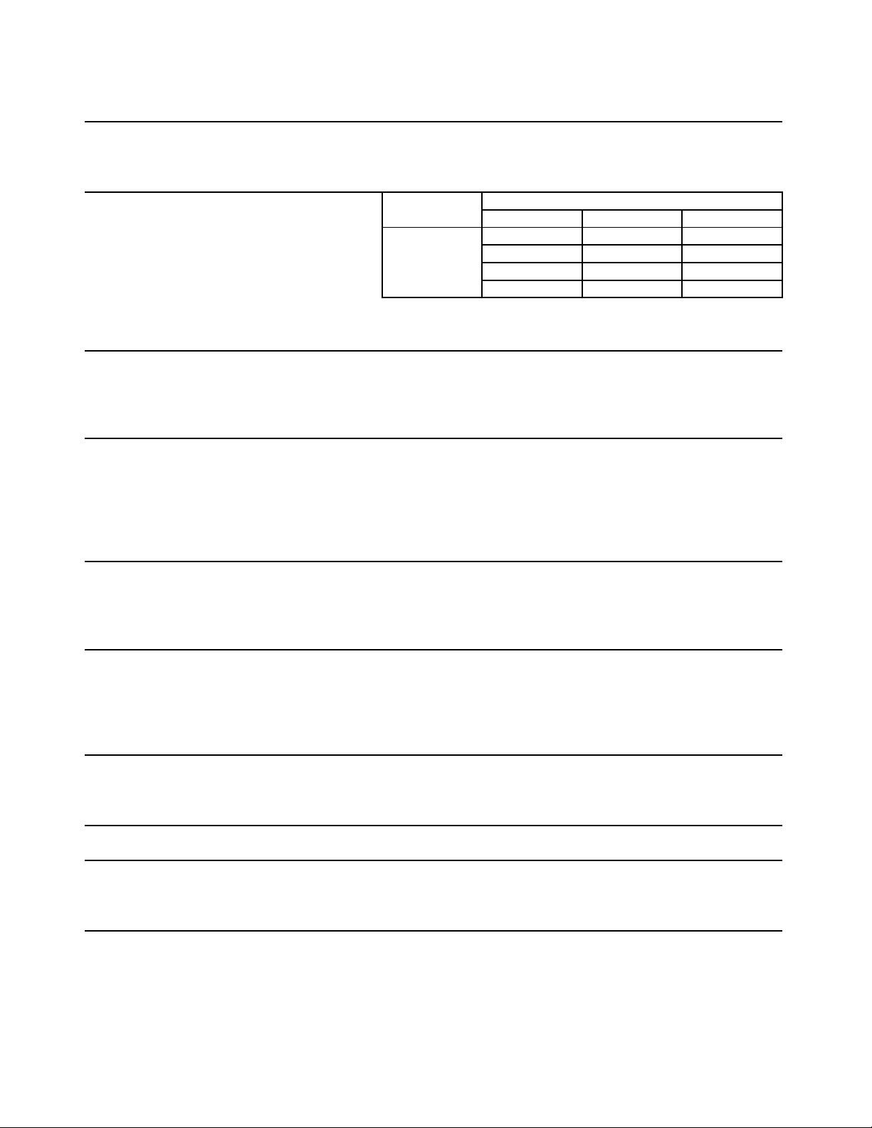
2. KM-650MWH (water-cooled)
SPECIFICATION NO. 06A020 ISSUED: 10/10/2006
ITEM: HOSHIZAKI MODULAR CRESCENT CUBER
MODEL: KM-650MWH
AC SUPPLY VOLTAGE 208-230/60/1 (3 wire with neutral for 115V)
AMPERAGE 5.3 A ( 5 Min. Freeze AT 104°F / WT 80°F)
MINIMUM CIRCUIT AMPACITY 15 A
MAXIMUM FUSE SIZE 15 A
APPROXIMATE ICE PRODUCTION Ambient WATER TEMP. (°F)
PER 24 HR. Temp.(°F) 50 70 90
lbs./day ( kg/day ) 70 *680 (308) 675 (306) 626 (284)
Reference without *marks 80 676 (307) 668 (303) 595 (270)
90 675 (306) *662 (300) 598 (271)
100 651 (295) 647 (294) 540 (245)
SHAPE OF ICE Crescent Cube
ICE PRODUCTION PER CYCLE 14.8 lbs. (6.7 kg) 720 pcs.
APPROXIMATE STORAGE CAPACITY N/A
ELECTRIC & WATER CONSUMPTION 90/70°F 70/50°F
ELECTRIC W (kWH/100 lbs.) 1050(3.8) 1020(3.6)
WATER gal./24HR (gal./100 lbs.) 149(22.5) 254(37.4)
WATER COOLED CONDENSER 741(112) 408(60)
gal./24HR (gal./100 lbs.)
EXTERIOR DIMENSIONS (WxDxH) 22" x 27-3/8" x 37-7/16" (560 x 695 x 950 mm)
EXTERIOR FINISH Stainless Steel, Galvanized Steel (Rear)
WEIGHT Net 169 lbs. (77 kg), Shipping 200 lbs. (91 kg)
CONNECTIONS - ELECTRIC Permanent - Connection
- WATER SUPPLY Inlet 1/2" FPT Condenser Inlet 1/2" FPT
- DRAIN Outlet 3/4" FPT Condenser Outlet 3/8" FPT
3/8" OD Tube
CUBE CONTROL SYSTEM Float Switch
HARVESTING CONTROL SYSTEM Hot Gas and Water, Thermistor and Timer
ICE MAKING WATER CONTROL Timer Controlled. Overflow Pipe
COOLING WATER CONTROL Pressure Regulator
BIN CONTROL SYSTEM Thermostat
COMPRESSOR Hermetic, Model RS55C2E-CAV
CONDENSER Water-cooled, Tube in tube type
EVAPORATOR Vertical type, Stainless Steel and Copper
REFRIGERANT CONTROL Thermostatic Expansion Valve
REFRIGERANT CHARGE R-404A, 1 lb. 5.7 oz. (615g)
DESIGN PRESSURE High 427PSIG, Low 230PSIG
P.C. BOARD CIRCUIT PROTECTION High Voltage Cut-out ( Internal )
COMPRESSOR PROTECTION Auto-reset Overload Protector ( Internal )
REFRIGERANT CIRCUIT PROTECTION Auto-reset High Pressure Control Switch
LOW WATER PROTECTION Float Switch
ACCESSORIES -SUPPLIED N/A
-REQUIRED Ice Storage Bin
OPERATING CONDITIONS VOLTAGE RANGE 187 - 253 V
AMBIENT TEMP. 45 -100° F
WATER SUPPLY TEMP. 45 - 90° F
WATER SUPPLY PRESSURE 10 - 113 PSIG
Note: We reserve the right to make changes in specifications and design without prior
notice.
6
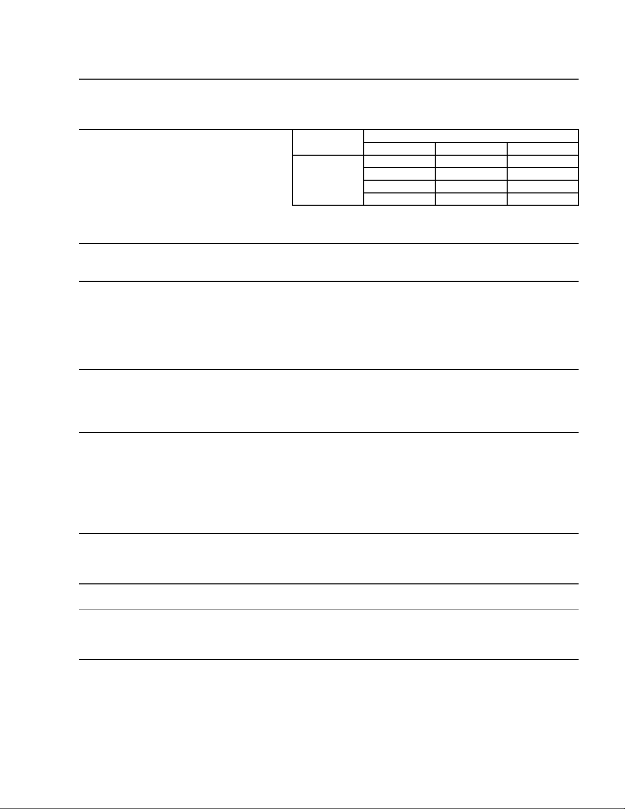
3. KM-650MRH (remote air-cooled)
SPECIFICATION DATA NO. 06A021
ITEM: HOSHIZAKI MODULAR CRESCENT CUBER
MODEL: KM-650MRH
AC SUPPLY VOLTAGE 208-230/60/1 (3 wire with neutral for 115V)
AMPERAGE 7.1 A ( 5 Min. Freeze AT 104°F / WT 80°F)
MINIMUM CIRCUIT AMPACITY 15 A
MAXIMUM FUSE SIZE 15 A
APPROXIMATE ICE PRODUCTION Ambient WATER TEMP. (°F)
PER 24 HR. Temp.(°F) 50 70 90
lbs./day ( kg/day ) 70 *615 (279) 597 (271) 556 (252)
Reference without *marks 80 601 (273) 574 (260) 523 (237)
90 597 (271) *554 (251) 506 (230)
100 583 (264) 543 (246) 462 (210)
SHAPE OF ICE Crescent Cube
ICE PRODUCTION PER CYCLE 14.1 lbs. (6.4 kg ) 720 pcs.
APPROXIMATE STORAGE CAPACITY N/A
ELECTRIC & WATER CONSUMPTION 90/70°F 70/50°F
ELECTRIC W (kWH/100 lbs.) 1250(5.4) 1150(4.5)
WATER gal./24HR (gal./100 lbs.) 111(20.0) 266(43.2)
EXTERIOR DIMENSIONS (WxDxH) 22" x 27-3/8" x 37-7/16" (560 x 695 x 950 mm)
EXTERIOR FINISH Stainless Steel, Galvanized Steel (Rear)
WEIGHT Net 169 lbs. (77 kg), Shipping 200 lbs. (91 kg)
CONNECTIONS - ELECTRIC Permanent - Connection
- WATER SUPPLY Inlet 1/2" FPT
- DRAIN Outlet 3/4" FPT
3/8" OD Tube
CUBE CONTROL SYSTEM Float Switch
HARVESTING CONTROL SYSTEM Hot Gas and Water, Thermistor and Timer
ICE MAKING WATER CONTROL Timer Controlled. Overflow Pipe
COOLING WATER CONTROL N/A
BIN CONTROL SYSTEM Thermostat
COMPRESSOR Hermetic, Model RS55C2E-CAV
CONDENSER Air-cooled Remote, Condenser Unit URC-5F
EVAPORATOR Vertical type, Stainless Steel and Copper
REFRIGERANT CONTROL Thermostatic Expansion Valve
Condensing Pressure Regulator on URC-5F
REFRIGERANT CHARGE R-404A, 5 lbs. 11 oz. (2580 g)
( Icemaker 3 lbs. 13 oz. Cond. Unit 1 lb. 14 oz. )
DESIGN PRESSURE High 467 PSIG, Low 230 PSIG
P.C. BOARD CIRCUIT PROTECTION High Voltage Cut-out ( Internal )
COMPRESSOR PROTECTION Auto-reset Overload Protector ( Internal )
REFRIGERANT CIRCUIT PROTECTION Auto-reset High Pressure Control Switch
LOW WATER PROTECTION Float Switch
ACCESSORIES -SUPPLIED N/A
-REQUIRED Ice Storage Bin, Remote Condenser Unit
OPERATING CONDITIONS VOLTAGE RANGE 187 - 253 V
AMBIENT TEMP. 45 -100° F
WATER SUPPLY TEMP. 45 - 90° F
WATER SUPPLY PRESSURE 10 - 113 PSIG
ISSUED: 10/10/2006
Note: We reserve the right to make changes in specifications and design without prior
notice.
7
B. Condensing Unit
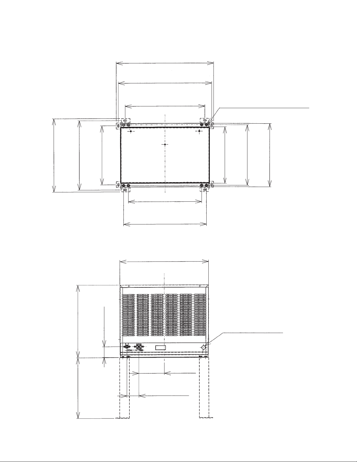
1. URC-5F
24"
(610 mm.)
23-1/32"
(585 mm.)
18-1/8"
(460 mm.)
17-1/8"
(435 mm.)
14-9/16"
(370 mm.)
19-11/16"
(500 mm.)
18-1/8"
(460 mm.)
20-15/32"
(520 mm.)
21-15/16"
(557 mm.)
6/16" x 3/4" (10 mm. x 20 mm.)
4 x 2 (SLOTTED HOLES)
14-1/8"
(358 mm.)
14-15/16"
15-11/16"
(380 mm.)
(398 mm.)
17-7/8"
(454 mm.)
14-15/16"
(380 mm.)
2-1/2"
(63 mm.)
7/8" DIA. HOLE
(23 mm. DIA.)
6-5/16"
(160 mm.)
2-15/16"
(75 mm.)
8
Specifications
SPECIFICATION NO. 06A022
ISSUED: 10/12/2006
ITEM: HOSHIZAKI REMOTE CONDENSER UNIT
MODEL URC-5F
BEGINNING SERIAL NO. ________________
ENDING SERIAL NO. ___________________
AC SUPPLY VOLTAGE 115/60/1 (Connection to Icemaker)
FAN MOTOR 115 V Total 1.3FLA 65W
EXTERIOR DIMENSIONS (WxDxH) 21-15/16" x 15-11/16" x 17-7/8" (557 x 398 x 454 mm)
DIMENSIONS INCLUDING LEGS (WxDxH) 24" x 18-1/8" x 32-13/16" (610 x 460 x 834 mm)
EXTERIOR FINISH Galvanized Steel
WEIGHT Net 61 lbs. ( 28 kg ) Shipping 68 lbs. ( 31 kg )
CONNECTIONS - ELECTRIC Permanent - Connection
- REFRIGERANT Discharge Line 1-1/16"-12 UNF Fitting (#10 AEROQUIP)
Liquid Line 5/8"-18 UNF Fitting (#6 AEROQUIP)
CONDENSER Air-cooled, Fin and tube type
FAN MOTOR PROTECTION Thermal Protection
REFRIGERANT CONTROL Condensing Pressure Regulator
REFRIGERANT CHARGE R-404A 1 lb. 14 oz. (850g)
DESIGN PRESSURE High 467 PSIG
OPERATING CONDITIONS VOLTAGE RANGE 104 ~ 127 V
AMBIENT TEMP. -20 ~ 122 °F
ACCESSORIES -SUPPLIED Leg 2 pcs
Hex. Head Bolt w/Washer 8 x 16 8 pcs
Hex. Nut 8 8 pcs
DRAWING NO. (DIMENSION) 441211
MODEL: URC-5F
Note: We reserve the right to make changes in specifications and design without prior
notice.
9
II. General Information
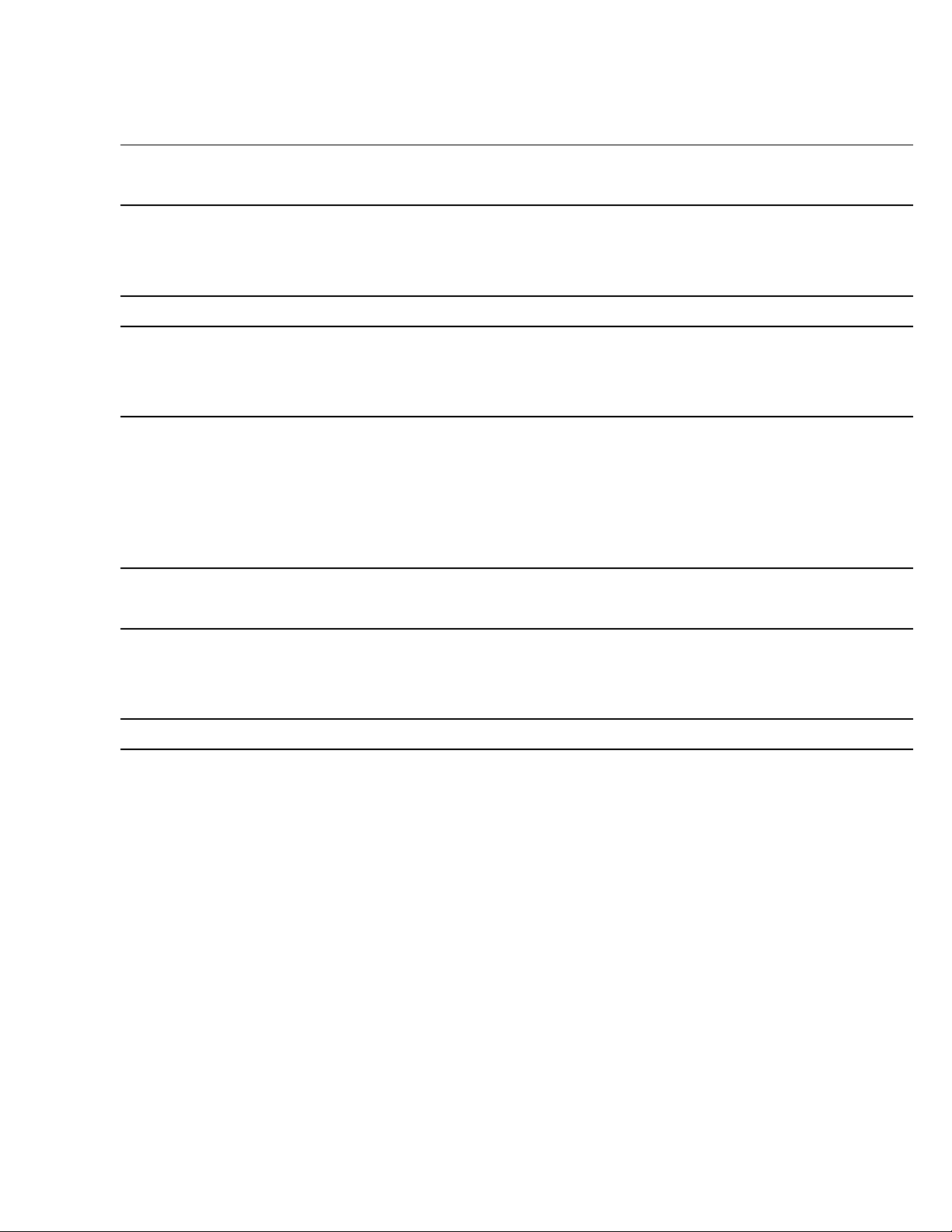
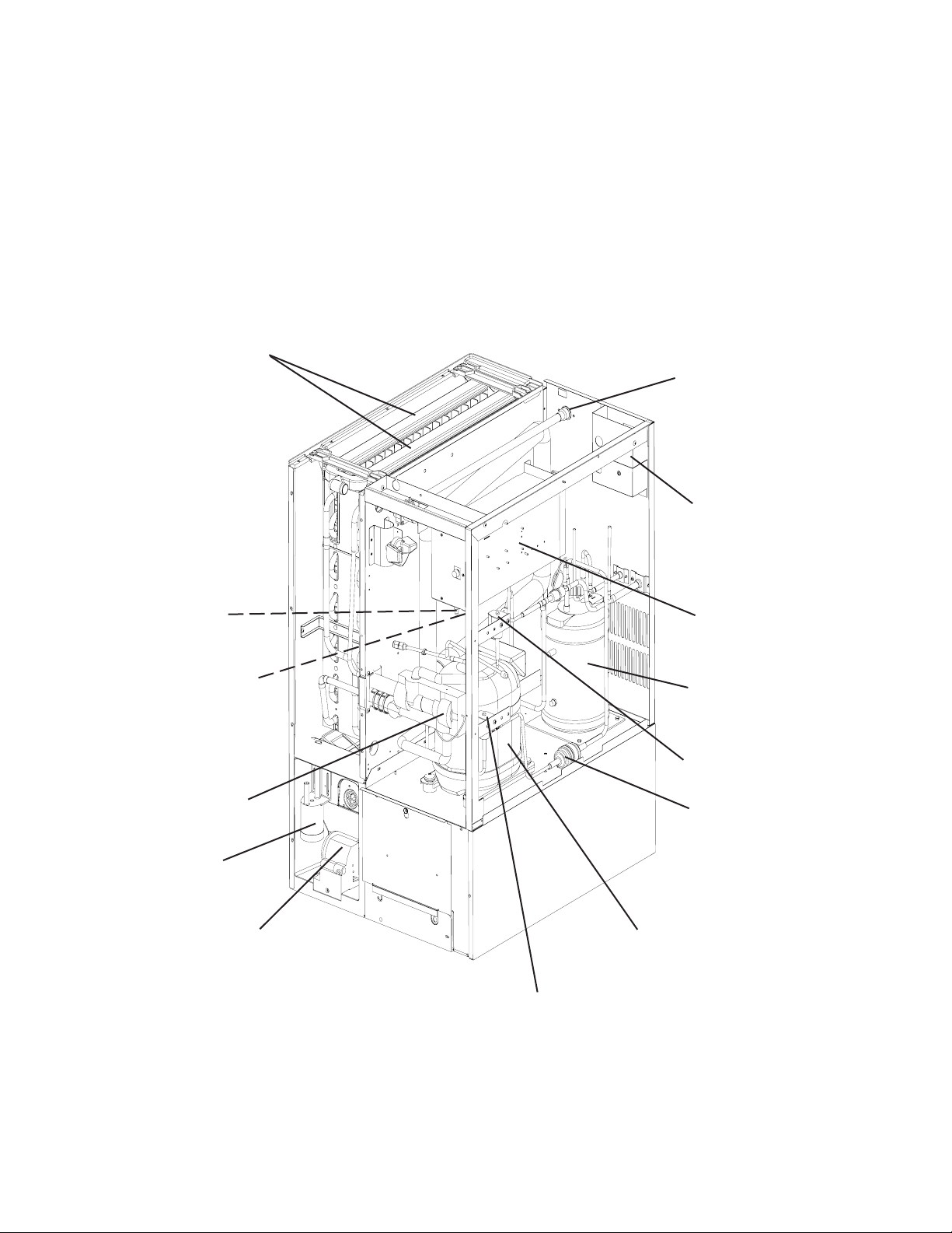
A. Construction
1. KM-650MAH (air-cooled)
Spray Tubes
Water Supply Inlet
Condenser
Control Switch
Bin Control Thermostat
Expansion Valve
Float Switch
Water Pump
Control Box
Fan Motor
Hot Gas Valve
Drier
Compressor
10
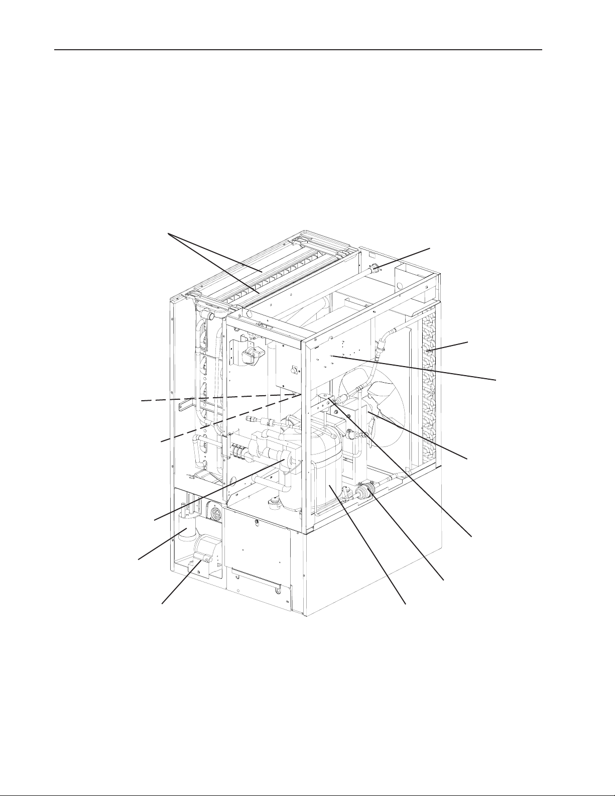
2. KM-650MWH (water-cooled)
Spray Tubes
Water Supply Inlet
Control Switch
Bin Control Thermostat
Expansion Valve
Float Switch
Water Pump
Water Regulator Valve
Control Box
Condenser
Drier
Hot Gas Valve
Compressor
11
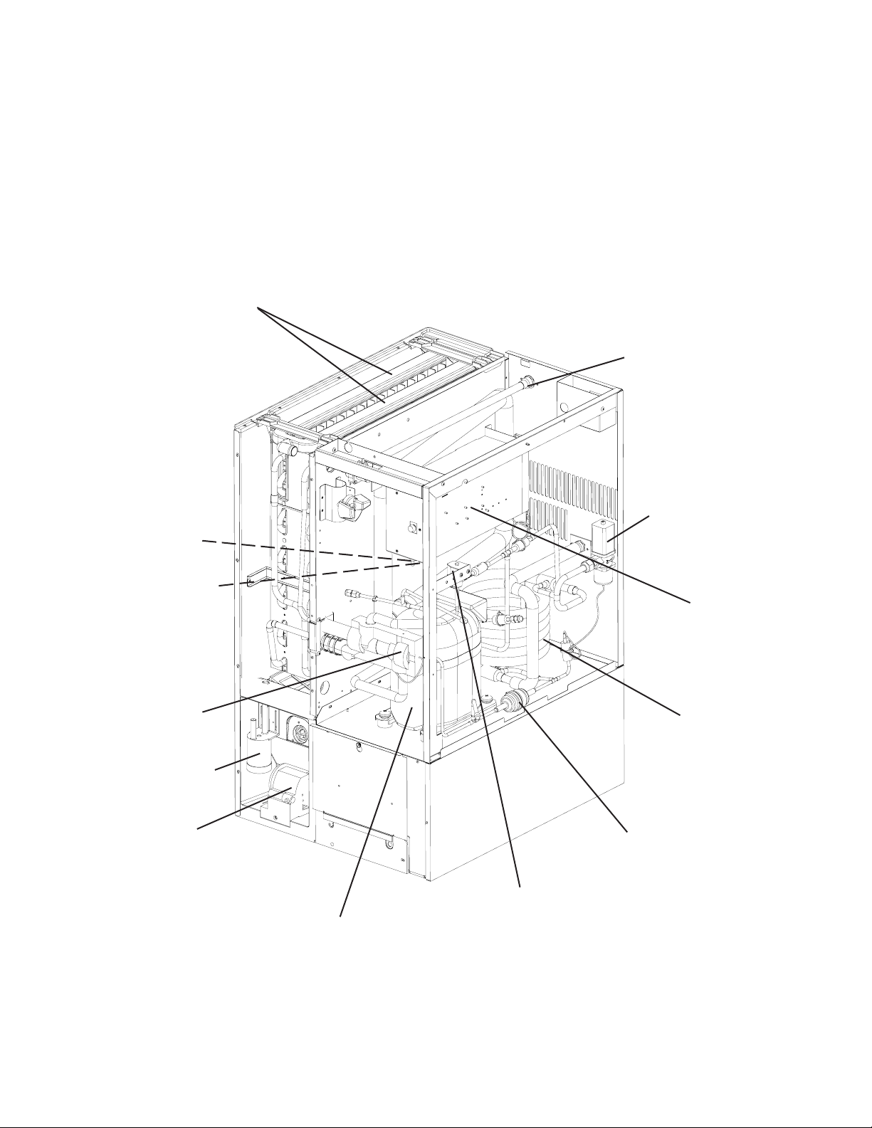
3. KM-650MRH (remote air-cooled)
Spray Tubes
Water Supply Inlet
Junction Box
Control Switch
Bin Control Thermostat
Expansion Valve
Float Switch
Water Pump
Control Box
Receiver Tank
Hot Gas Valve
Drier
Compressor
Liquid Line Valve
12

B. Sequence of Operation
The steps in the sequence are as outlined below. When power is supplied, a 5 second
delay occurs at startup. Note that the order of the LEDs from the outer edge of the board is
1, 4, 3, 2.
1. One Minute Fill Cycle
LED 4 is on. WV opens and the fill period begins. After 1 minute, the board checks for
a closed F/S. If F/S is closed, the harvest cycle begins. If not, WV will remain energized
through additional 1 minute cycles until water enters the sump and F/S closes. This serves
as a low water safety to protect the water pump.
2. Initial Harvest Cycle
LEDs 1, 4, and 2 are on. WV remains open, Comp and FMR energize, HGV opens,
and harvest begins. As the evaporator warms, the thermistor located on the suction line
checks for a 48°F (9°C) temperature. When 48°F (9°C) is reached, a 3.9 kΩ signal turns
the harvest over to the adjustable harvest timer which is factory set for normal conditions.
The timer has settings of 60, 90, 120, and 180 seconds (dip switch 1 & 2). The water valve
is open during harvest for a maximum of 6 minutes or the length of harvest, whichever is
shorter. When the harvest timer completes its count down, the harvest cycle is complete
and the freeze cycle starts. The minimum total time allowed by the board for a complete
harvest cycle is 2 minutes.
3. Freeze Cycle
LED 1 is on. Comp and FMR continue to run, PM and FMS energize, LLV opens, HGV
and WV close and the freeze cycle starts. For the first 5 minutes the control board will not
accept a signal from F/S. This 5 minute minimum freeze acts as a short cycle protection. At
the end of 5 minutes, F/S assumes control. As ice builds on the evaporator the water level
in the sump lowers. The freeze continues until F/S opens and terminates ice production.
4. Pump-Out Cycle
LEDs 1, 3, and 2 are on. Comp and FMR continue to run, HGV opens, LLV closes, and
FMS deenergizes. PM stops for 2 seconds and reverses, taking water from the bottom of
the sump and forcing pressure against the check valve seat allowing water to go through
the check valve and down the drain. At the same time water flows through the small tube
to power flush the F/S. When the pump-out timer stops counting, the pump out is complete.
Pump out always occurs on the 2nd harvest after startup. Then, depending on the control
board setting, pump out occurs every cycle, or every 2nd, 5th or 10th cycle (dip switch 5 &
6).
5. Normal Harvest Cycle
LEDs 1, 4, and 2 are on. Comp and FMR continue to run, HGV remains open and WV
opens. As the evaporator warms, the thermistor reaches 48°F (9°C). The control board
then receives the thermistor's 3.9 kΩ signal and starts the harvest timer. The water valve
is open during harvest for a maximum of 6 minutes or the length of harvest, whichever is
shorter. When the harvest timer completes its count down, the harvest cycle is complete
and the next freeze cycle starts. The unit continues to cycle through 3, 4 and 5 sequence
until the bin control senses ice and shuts the unit down.
Legend: Comp–compressor; FMR–remote fan motor; FMS–self-contained fan motor;
F/S–float switch; HGV–hot gas valve; LLV–Liquid Line Valve; PM–pump motor;
WV–inlet water valve
13
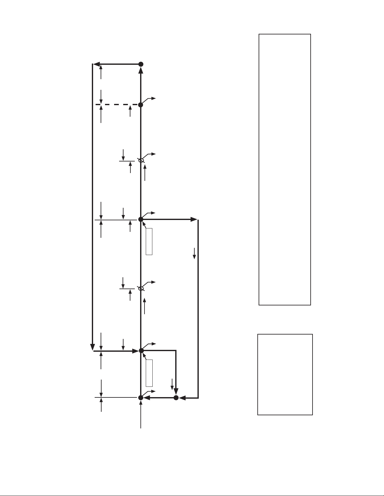
Cycle
4. Pump-Out
F/S in
control
5 minute timer
in control
• Minimum freeze time: 5 minutes
• Maximum freeze time: freeze timer setting
Pump motor stops
for 2 sec. and then
Freeze cycle
operation turned
over to F/S
F/S closed
Comp continues
FMR continues
HGV de-energized
F/S Check
reverses for 10/20 sec.
each 1, 2, 5, or 10 cycles.
Comp continues
FMR continues
HGV energized
FMS de-energized
WV de-energized
PM energized
FMS energized
F/S open
1 to 3 minute timer
in control
Thermistor temp
reaches 48°F (9°C)
2. Harvest Cycle 3. Freeze Cycle
Thermistor in
• Maximum harvest time: 20 minutes
Fill Cycle
control
F/S closed
Initial startup always
begins here
Comp energized
HGV energized
F/S Check
WV Energized
"E" board will have
5 second delay
• Maximum inlet water valve time: 6 minutes
1. One Minute
KM-650MAH, KM-650MWH, KM-650MRH Sequence Flow Chart and Component Operation
Cycle Steps
(3.9 kΩ or less)
Harvest timer starts
FMR energized
WV continues
F/S open
If F/S is open, compressor stops and cycle returns to 1 minute fill
Components Energized when the Control Switch is in the WASH Position
The WASH position on the control switch is used when cleaning and sanitizing the unit. When in the WASH
position, power is supplied to the pump motor. With the cleaning valve closed, the cleaner and sanitizer flow
Legend:
Comp - compressor
FMR - remote fan motor
FMS - self-contained fan motor
over the outside of the evaporator plate assembly. With the cleaning valve open, the cleaner and sanitizer
F/S - float switch
flow over both the outside and the inside of the evaporator plate assembly.
Note: Close the cleaning valve after cleaning and sanitizing are complete, otherwise the unit will not re-start
HGV - hot gas valve
when the control switch is placed in the ICE position.
PM - pump motor
WV - inlet water valve
14

C. Control Board
• A HOSHIZAKI exclusive solid-state control is employed in KM-650MAH, KM-650MWH
and KM-650MRH Modular Crescent Cubers.
• All models are pretested and factory-adjusted.
CAUTION
1. Fragile, handle very carefully.
2. A control board contains integrated circuits, which are susceptible to failure
due to static discharge. It is especially important to touch the metal part of
the unit when handling or replacing the board.
3. Do not touch the electronic devices on the board or the back of the board to
prevent damage to the board.
4. Do not change wiring and connections. Do not misconnect K3, K4 and K5,
because the same connector is used for the thermistor and float switch. K4 is
not connected.
5. Always replace the whole board assembly if it goes bad.
6. Do not short out power supply to test for voltage.
15
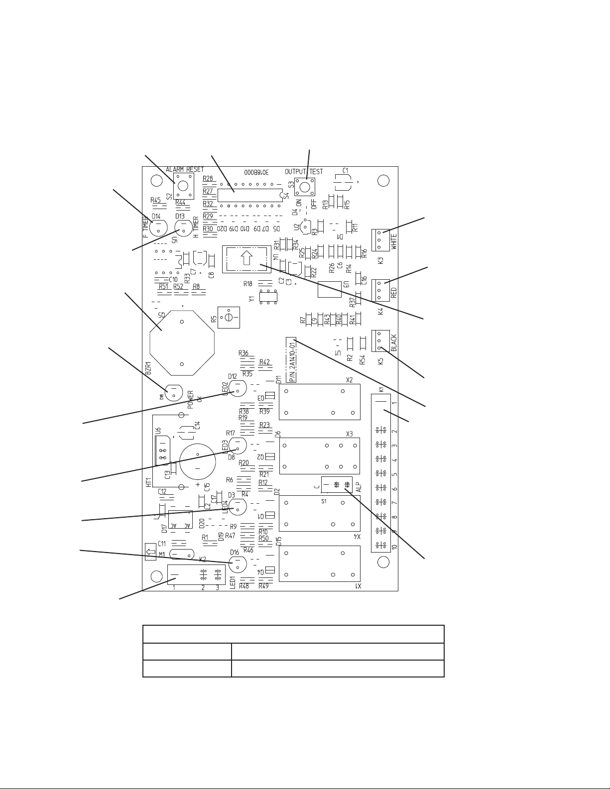
1. Control Board Layout
Control Products "E" Control Board
Alarm Reset Switch
Backup Freeze
Timer LED
Backup Harvest
Timer LED
Alarm Buzzer
Dip Switch
Output Test Switch
(used to test relays on board)
Connector K3
Harvest Control
(thermistor)
Connector K4
Open
(not connected)
Power LED
(lights when
power is supplied
to the board)
Relay LEDs (4)
(indicate which
relays are energized
as listed below)
LED 2
Hot Gas Valve (HGV)
Self-Contained Fan
Motor (FMS) (FMS
off when LED on)
LED 3
Pump Motor (PM)
(on at pump out only)
LED 4
Water Valve (WV)
LED 1
Compressor (Comp)
Remote Fan Motor
(FMR)
Transformer
Connector
Microprocessor
(board revision level
indicated by last 2
digits on label)
Connector K5
Float Switch
Part Number
Connector K1
Pins #1 through #10
#1, 9 Magnetic Contactor
#2 Hot Gas Valve
#3 Line Valve
Self-Contained Fan Motor (FMS)
#4 Pump Motor (icemaking)
#5 Pump Motor (drain)
#6 Water Valve
#7, 10 Power (line, bin control)
#8 Open
Switch for "C" board
and "ALPINE" board
(service boards only)
Control Board
Part Number 2A1410-01 (factory); 2A1410-02 (service)
Type HOS-001A (Control Products - 10 Pin)
16

2. Features
a) Maximum Water Supply Period – 6 minutes
Inlet water valve opening, in the harvest cycle, is limited by the harvest timer. The water
valve cannot remain open longer than the maximum period. The water valve can close in
less than six minutes if the harvest cycle is completed.
b) Harvest Backup Timer and Freeze Timer
The harvest backup timer shuts down the icemaker if, for two cycles in a row, the harvest
cycle takes more than 20 minutes to complete. The control board will signal this problem
using 2 beeps every 3 seconds.
The freeze timer shuts down the icemaker if, for two cycles in a row, the freeze cycle
takes longer than the time specified to complete. The control board will signal this
problem using 3 beeps every 3 seconds. The time is factory set using dip switches 9 &
10.
The reset button on the control board must be pressed with power on to reset either of
these safeties.
c) High Temperature Safety
The temperature of the suction line in the refrigeration circuit is limited by the high
temperature safety. This protects the unit from excessively high temperatures. If the
evaporator temperature rises above 127 ± 7°F (53 ± 4°C), the thermistor operates the
safety. This shuts down the circuit and the icemaker automatically stops.
The control board will signal this problem using 1 beep every 3 seconds. The reset button
on the control board must be pressed with power on to reset the safety.
d) Low Water Safety
If the pump motor is operated without water, the mechanical seal can fail. To prevent this
type of failure, the control board checks the position of the float switch at the end of the
initial one minute water fill cycle and at the end of each harvest cycle.
If the float switch is in the up position (electrical circuit closed), the control board changes
to the ice making cycle. If the float switch is in the down position (electrical circuit open),
the control board changes to additional one minute water fill cycles until water enters the
sump and the float switch closes. When the float switch closes, the control board changes
to the ice making cycle. The unit will not start without adequate water in the sump. This
serves as a low water safety to protect the pump motor from mechanical seal failure.
For water-cooled model, if the water is shut off, the unit is protected by the high pressure
switch.
e) High Voltage and Low Voltage Cut-outs
The maximum and minimum allowable supply voltages of this icemaker are limited by the
high voltage and low voltage cut-outs.
If miswiring (especially on single phase 3 wire models) causes excessive voltage (147Vac
±5% or more) on the control board, the high voltage cut-out shuts down the circuit
in 3 seconds and the icemaker automatically stops. The control board will signal this
problem using 7 beeps every 3 seconds.
The icemaker also automatically stops in cases of insufficient voltage (92Vac ±5% or
less). The control board will signal this problem using 6 beeps every 3 seconds.
When the proper supply voltage is resumed, the icemaker automatically starts running
again.
17
Loading...