


KM-1301SAH-3
Table of contents
 Loading...
Hoshizaki
“A Superior Degree
of Reliability”
www.hoshizaki.com
Models
KM-1301SAH/3
KM-1301SWH/3
KM-1301SRH/3
Stackable Crescent Cuber
Hoshizaki America, Inc.
SERVICE MANUAL
™
Number: 73169
Issued:1-21-2009
Revised: 8-6-2009

IMPORTANT
Only qualied service technicians should install, service, and maintain the
icemaker. No service or maintenance should be undertaken until the technician
has thoroughly read this Service Manual. Failure to service and maintain
the equipment in accordance with this manual may adversely affect safety,
performance, component life, and warranty coverage.
Hoshizaki provides this manual primarily to assist qualied service technicians in the
service and maintenance of the icemaker.
Should the reader have any questions or concerns which have not been satisfactorily
addressed, please call, write, or send an e-mail message to the Hoshizaki Technical
Support Department for assistance.
HOSHIZAKI AMERICA, INC.
618 Highway 74 South
Peachtree City, GA 3069
Attn: Hoshizaki Technical Support Department
Phone: 1-800-33-1940 Technical Support
(770) 487-331
Fax: 1-800-843-1056
(770) 487-3360
E-mail: techsupport@hoshizaki.com
Web Site: www.hoshizaki.com
NOTE: To expedite assistance, all correspondence/communication MUST include the
following information:
• Model Number
• Serial Number
• Complete and detailed explanation of the problem.

3
CONTENTS
Important Safety Information ................................................................................................. 6
I. Specications ..................................................................................................................... 7
A. Icemaker ....................................................................................................................... 7
1. KM-1301SAH (air-cooled) ....................................................................................... 7
. KM-1301SAH3 (air-cooled) ..................................................................................... 8
3. KM-1301SWH (water-cooled) ................................................................................ 9
4. KM-1301SWH3 (water-cooled) ............................................................................. 10
5. KM-1301SRH (remote air-cooled) ......................................................................... 11
6. KM-1301SRH3 (remote air-cooled) ....................................................................... 1
B. Condenser Unit ........................................................................................................... 13
1. URC-14F ............................................................................................................... 13
II. General Information ......................................................................................................... 15
A. Construction ................................................................................................................ 15
1. KM-1301SAH, KM-1301SAH3 (air-cooled) ........................................................... 15
. KM-1301SWH, KM-1301SWH3 (water-cooled) .................................................... 16
3. KM-1301SRH, KM-1301SRH3 (remote air-cooled) .............................................. 17
B. Sequence of Operation ............................................................................................... 18
1. Sequence Cycles and Shutdown .......................................................................... 18
a) 1-Minute Fill Cycle ........................................................................................... 18
b) Initial Harvest Cycle ........................................................................................ 18
c) Freeze Cycle ................................................................................................... 18
d) Pump-Out Cycle ............................................................................................. 19
e) Harvest Cycle ................................................................................................. 19
f) Shutdown .......................................................................................................... 19
. Sequence Flow Chart ............................................................................................ 0
C. Control Board ............................................................................................................. 1
1. Control Board Layout ............................................................................................
. Features ................................................................................................................ 3
a) Maximum Water Supply Period - 6 minutes .................................................... 3
b) Harvest Backup Timer and Freeze Timer ........................................................ 3
c) High Temperature Safety ................................................................................. 3
d) Low Water Safety ............................................................................................ 3
e) High Voltage and Low Voltage Cut-outs .......................................................... 3
f) LED Lights and Audible Alarm Safeties ............................................................ 4
3. Controls and Adjustments ..................................................................................... 5
a) Default Dip Switch Settings ............................................................................. 5
b) Harvest Timer (S4 dip switch 1 & ) ................................................................ 5
c) Pump-Out Timer (S4 dip switch 3 & 4) ............................................................ 6
d) Pump-Out Frequency Control (S4 dip switch 5 & 6) ........................................ 6
IMPORTANT
This manual should be read carefully before the icemaker is serviced or
maintenance operations are performed. Only qualied service technicians
should install, service, and maintain the icemaker. Read the warnings
contained in this booklet carefully as they give important information regarding
safety. Please retain this booklet for any further reference that may be
necessary.

4
e) Harvest Pump Timer (S4 dip switch 7) ............................................................ 7
f) Factory Use (S4 dip switch 8) ........................................................................... 7
g) Freeze Timer (S4 dip switch 9 & 10) ............................................................... 7
h) Float Switch Control (S5 dip switch 1) ............................................................ 8
i) Rell Counter (S5 dip switch through 5) ........................................................ 8
D. Bin Control .................................................................................................................. 9
E. Float Switch ................................................................................................................ 9
F. Thermistor ................................................................................................................... 9
G. Control Switch ............................................................................................................ 9
III. Technical Information ..................................................................................................... 30
A. Water Circuit and Refrigeration Circuit ....................................................................... 30
1. KM-1301SAH, KM-1301SAH3 (air-cooled) ........................................................... 30
. KM-1301SWH, KM-1301SWH3 (water-cooled) .................................................... 31
3. KM-1301SRH, KM-1301SRH3 (remote air-cooled) ............................................... 3
B. Wiring Diagrams ......................................................................................................... 33
1. Auxiliary Code T-0, U-0 ........................................................................................ 33
a) KM-1301SAH (air-cooled) ................................................................................ 33
b) KM-1301SWH (water-cooled) .......................................................................... 34
c) KM-1301SRH (remote air-cooled) ................................................................... 35
d) KM-1301SAH3 (air-cooled) and KM-1301SWH3 (water-cooled) ..................... 36
e) KM-1301SRH3 (remote air-cooled) ................................................................. 37
. Auxiliary Code U-1 and Later ............................................................................... 38
a) KM-1301SAH (air-cooled) ............................................................................... 38
b) KM-1301SWH (water-cooled) ......................................................................... 39
c) KM-1301SRH (remote air-cooled) ................................................................... 40
d) KM-1301SAH3 (air-cooled) and KM-1301SWH3 (water-cooled) ..................... 41
e) KM-1301SRH3 (remote air-cooled) ................................................................. 4
C. Performance Data ...................................................................................................... 43
1. KM-1301SAH (air-cooled) ..................................................................................... 43
. KM-1301SAH3 (air-cooled) ................................................................................... 44
3. KM-1301SWH (water-cooled) .............................................................................. 45
4. KM-1301SWH3 (water-cooled) ............................................................................ 46
5. KM-1301SRH (remote air-cooled) ........................................................................ 47
6. KM-1301SRH3 (remote air-cooled) ....................................................................... 48
IV. Service Diagnosis .......................................................................................................... 49
A. Diagnostic Procedure ................................................................................................ 49
B. Control Board Check .................................................................................................. 53
C. Bin Control Check ....................................................................................................... 54
D. Float Switch Check and Cleaning ............................................................................... 54
1. Float Switch Check ................................................................................................ 54
. Float Switch Cleaning ............................................................................................ 55
E. Thermistor Check ....................................................................................................... 56
F. Diagnostic Charts ........................................................................................................ 57

5
V. Removal and Replacement of Components ................................................................... 65
A. Service for Refrigerant Lines ...................................................................................... 65
1. Refrigerant Recovery ............................................................................................ 65
. Brazing .................................................................................................................. 66
3. Evacuation and Recharge (R-404A) ..................................................................... 66
B. Removal and Replacement of Compressor ................................................................ 67
C. Removal and Replacement of Expansion Valve......................................................... 68
D. Removal and Replacement of Hot Gas Valve or Liquid Line Valve............................ 69
E. Removal and Replacement of Evaporator .................................................................. 70
F. Removal and Replacement of Air-Cooled Condenser ................................................ 71
G. Removal and Replacement of Water-Cooled Condenser .......................................... 7
H. Removal and Replacement of Remote Air-Cooled Condenser .................................. 73
I. Removal and Replacement of Water Regulating Valve (water-cooled model) ............ 74
J. Adjustment of Water Regulating Valve (water-cooled model) .................................... 75
K. Removal and Replacement of Headmaster (Condensing Pressure Regulator - C.P.R.)
(remote air-cooled model) ......................................................................................... 75
L. Removal and Replacement of Thermistor ................................................................... 76
M. Removal and Replacement of Fan Motor (air-cooled and remote air-cooled models) 77
N. Removal and Replacement of Inlet Water Valve ........................................................ 77
O. Removal and Replacement of Pump Motor................................................................ 78
P. Removal and Replacement of Control Board ............................................................. 79
VI. Cleaning and Maintenance ............................................................................................ 80
A. Cleaning and Sanitizing Instructions ........................................................................... 80
1. Cleaning Procedure ............................................................................................... 81
. Sanitizing Procedure - Following Cleaning Procedure .......................................... 8
B. Maintenance Instructions ............................................................................................ 83
C. Preparing the Icemaker for Long Storage .................................................................. 83
6
Important Safety Information
Throughout this manual, notices appear to bring your attention to situations which could
result in death, serious injury, or damage to the unit.
WARNING Indicates a hazardous situation which could result in death or
serious injury.
CAUTION Indicates a situation which could result in damage to the unit.
IMPORTANT Indicates important information about the use and care of the
unit.
WARNING
This icemaker should be destined only to the use for which it has been
expressly conceived. Any other use should be considered improper and
therefore dangerous. The manufacturer cannot be held responsible for
eventual damage caused by improper, incorrect, and unreasonable use.
To reduce the risk of death, electric shock, serious injury, or re, follow
basic precautions including the following:
• Electrical connection must be hard-wired and must meet national, state, and
local electrical code requirements. Failure to meet these code requirements
could result in death, electric shock, serious injury, re, or severe damage to
equipment.
• This unit requires an independent power supply. See the nameplate for
proper voltage and breaker/fuse size. Failure to use a proper breaker or fuse
can result in a tripped breaker, blown fuse, or damage to existing wiring. This
could lead to heat generation or re.
• THIS UNIT MUST BE GROUNDED. Failure to properly ground this unit
could result in death or serious injury.
• This unit should be disassembled or repaired only by qualied service
personnel to reduce the risk of electric shock, injury, or re.
• Do not make any alterations to the unit. Alterations could result in electric
shock, injury, re, or damage to the unit.
7
I. Specications
A. Icemaker
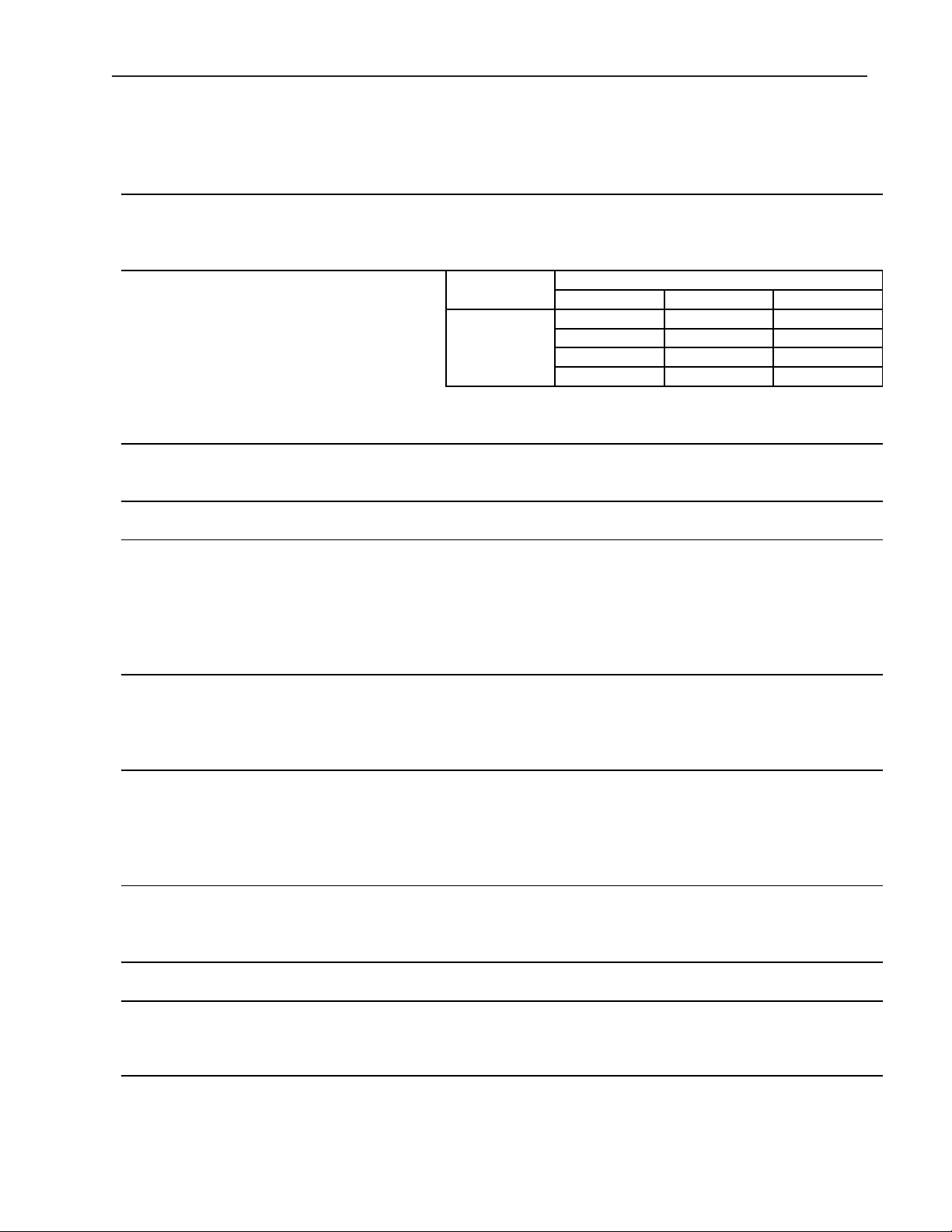
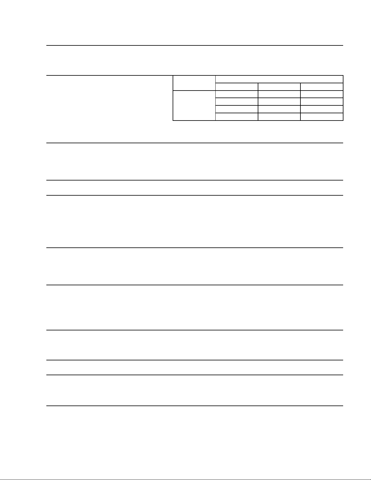
1. KM-1301SAH (air-cooled)
Note: We reserve the right to make changes in specications and design without prior
notice.
AC SUPPLY VOLTAGE 208-230/60/1 (3 wire with neutral for 115V)
AMPERAGE 12.4 A ( 5 Min. Freeze AT 104°F / WT 80°F)
MINIMUM CIRCUIT AMPACITY 20 A
MAXIMUM FUSE SIZE 20 A
APPROXIMATE ICE PRODUCTION Ambient WATER TEMP. (°F)
PER 24 HR. Temp.(°F) 50 70 90
lbs./day ( kg/day ) 70 *1329 (603) 1281 (581) 1188 (539)
Reference without *marks 80 1292 (586) 1217 (552) 1109 (503)
90 1281 (581) *1164 (528) 1060 (481)
100 1253 (568) 1140 (517) 965 (438)
SHAPE OF ICE Crescent Cube
ICE PRODUCTION PER CYCLE 29.8 lbs. (13.5 kg) 1440pcs.
APPROXIMATE STORAGE CAPACITY N/A
ELECTRIC & WATER CONSUMPTION 90/70°F 70/50°F
ELECTRIC W (kWH/100 lbs.) 2180(4.5) 2160(3.9)
WATER gal./24HR (gal./100 lbs.) 183(15.7) 605(45.5)
CEC/CEE TIER LEVEL 3
ENERGY STAR YES
EXTERIOR DIMENSIONS (WxDxH) 48" x 27-3/8" x 27-3/8" (1219 x 695 x 695 mm)
EXTERIOR FINISH Stainless Steel, Galvanized Steel (Rear)
WEIGHT Net 275 lbs. (125 kg), Shipping 315 lbs. (143 kg)
CONNECTIONS - ELECTRIC Permanent - Connection
- WATER SUPPLY Inlet 1/2" FPT
- DRAIN Outlet 3/4" FPT
- CONDENSATE DRAIN 3/8" OD Tube
CUBE CONTROL SYSTEM Float Switch
HARVESTING CONTROL SYSTEM Hot Gas and Water, Thermistor and Timer
ICE MAKING WATER CONTROL Timer Controlled. Overflow Pipe
COOLING WATER CONTROL N/A
BIN CONTROL SYSTEM Thermostat
COMPRESSOR Hermetic, Model CS14K6E-PFV-237
CONDENSER Air-Cooled , Fin and tube type
EVAPORATOR Vertical type, Stainless Steel and Copper
REFRIGERANT CONTROL Thermostatic Expansion Valve
REFRIGERANT CHARGE R404A, 3 lb. 15.5 oz. (1800g)
DESIGN PRESSURE High 467PSIG, Low 230PSIG
P.C. BOARD CIRCUIT PROTECTION High Voltage Cut-out ( Internal )
COMPRESSOR PROTECTION Auto-reset Overload Protector ( Internal )
REFRIGERANT CIRCUIT PROTECTION Auto-reset High Pressure Control Switch
LOW WATER PROTECTION Float Switch
ACCESSORIES -SUPPLIED N/A
-REQUIRED Ice Storage Bin
OPERATING CONDITIONS VOLTAGE RANGE 187 - 253 V
AMBIENT TEMP. 45 -100° F
WATER SUPPLY TEMP. 45 - 90° F
WATER SUPPLY PRESSURE 10 - 113 PSIG
8
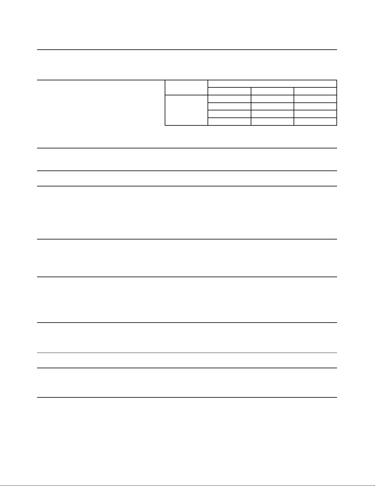
Note: We reserve the right to make changes in specications and design without prior
notice.
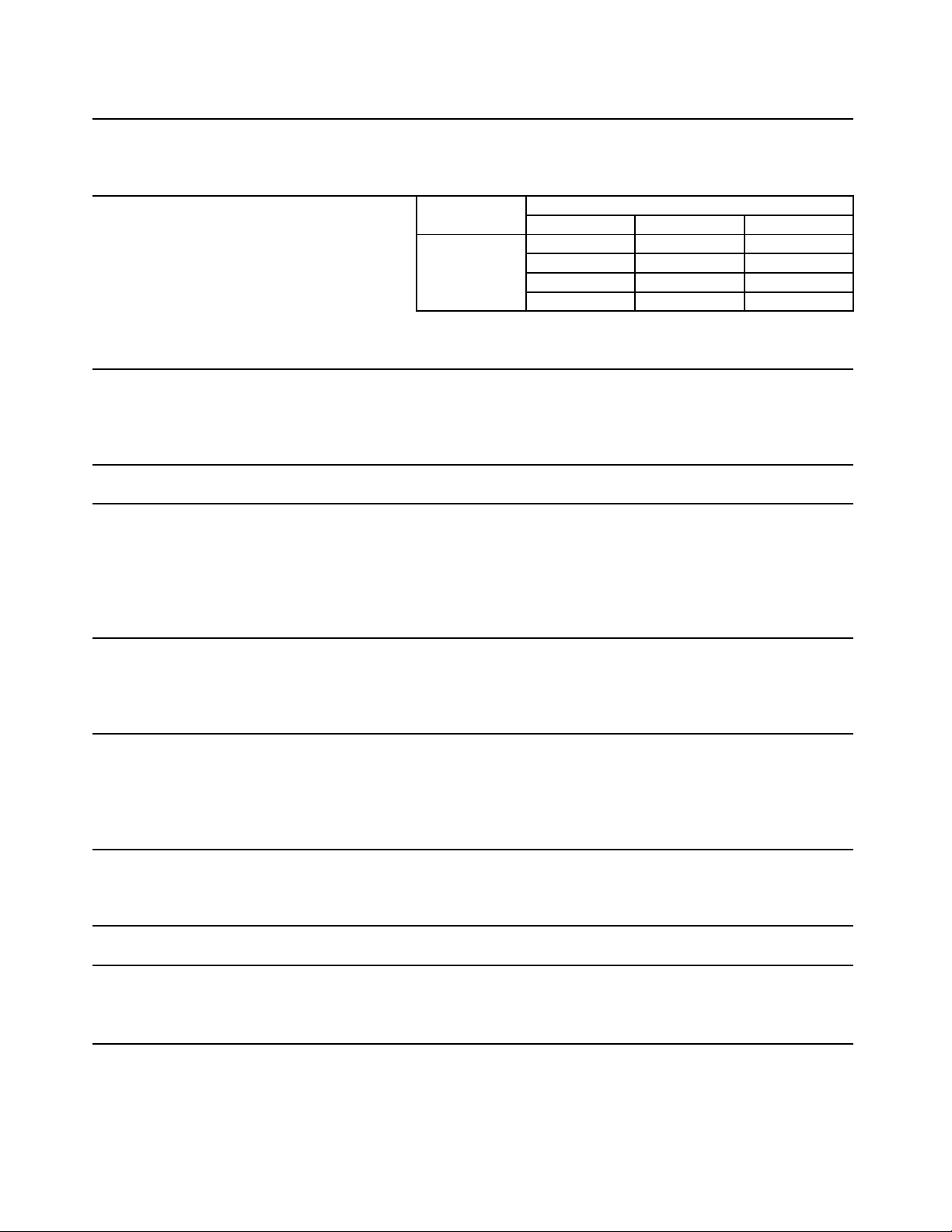
2. KM-1301SAH3 (air-cooled)
AC SUPPLY VOLTAGE 208-230/60/3
AMPERAGE 9.5 A ( 5 Min. Freeze AT 104°F / WT 80°F)
MINIMUM CIRCUIT AMPACITY 20 A
MAXIMUM FUSE SIZE 20 A
APPROXIMATE ICE PRODUCTION Ambient WATER TEMP. (°F)
PER 24 HR. Temp.(°F) 50 70 90
lbs./day ( kg/day ) 70 *1298 (589) 1257 (570) 1162 (527)
Reference without *marks 80 1267 (575) 1204 (546) 1086 (493)
90 1257 (570) *1159 (526) 1049 (476)
100 1225 (556) 1133 (514) 947 (430)
SHAPE OF ICE Crescent Cube
ICE PRODUCTION PER CYCLE 30.4 lbs. (13.8 kg) 1440pcs.
APPROXIMATE STORAGE CAPACITY N/A
ELECTRIC & WATER CONSUMPTION 90/70°F 70/50°F
ELECTRIC W (kWH/100 lbs.) 2220(4.6) 2090(3.9)
WATER gal./24HR (gal./100 lbs.) 181(15.6) 511(39.4)
CEC/CEE TIER LEVEL 3
ENERGY STAR YES
EXTERIOR DIMENSIONS (WxDxH) 48" x 27-3/8" x 27-3/8" (1219 x 695 x 695 mm)
EXTERIOR FINISH Stainless Steel, Galvanized Steel (Rear)
WEIGHT Net 275 lbs. (125 kg), Shipping 315 lbs. (143 kg)
CONNECTIONS - ELECTRIC Permanent - Connection
- WATER SUPPLY Inlet 1/2" FPT
- DRAIN Outlet 3/4" FPT
- CONDENSATE DRAIN 3/8" OD Tube
CUBE CONTROL SYSTEM Float Switch
HARVESTING CONTROL SYSTEM Hot Gas and Water, Thermistor and Timer
ICE MAKING WATER CONTROL Timer Controlled. Overflow Pipe
COOLING WATER CONTROL N/A
BIN CONTROL SYSTEM Thermostat
COMPRESSOR Hermetic, Model CS14K6E-TF5-237
CONDENSER Air-Cooled, Fin and tube type
EVAPORATOR Vertical type, Stainless Steel and Copper
REFRIGERANT CONTROL Thermostatic Expansion Valve
REFRIGERANT CHARGE R404A, 3 lb. 15.5 oz. (1800g)
DESIGN PRESSURE High 467PSIG, Low 230PSIG
P.C. BOARD CIRCUIT PROTECTION High Voltage Cut-out ( Internal )
COMPRESSOR PROTECTION Auto-reset Overload Protector ( Internal )
REFRIGERANT CIRCUIT PROTECTION Auto-reset High Pressure Control Switch
LOW WATER PROTECTION Float Switch
ACCESSORIES -SUPPLIED N/A
-REQUIRED Ice Storage Bin
OPERATING CONDITIONS VOLTAGE RANGE 187 - 253 V
AMBIENT TEMP. 45 -100° F
WATER SUPPLY TEMP. 45 - 90° F
WATER SUPPLY PRESSURE 10 - 113 PSIG
9
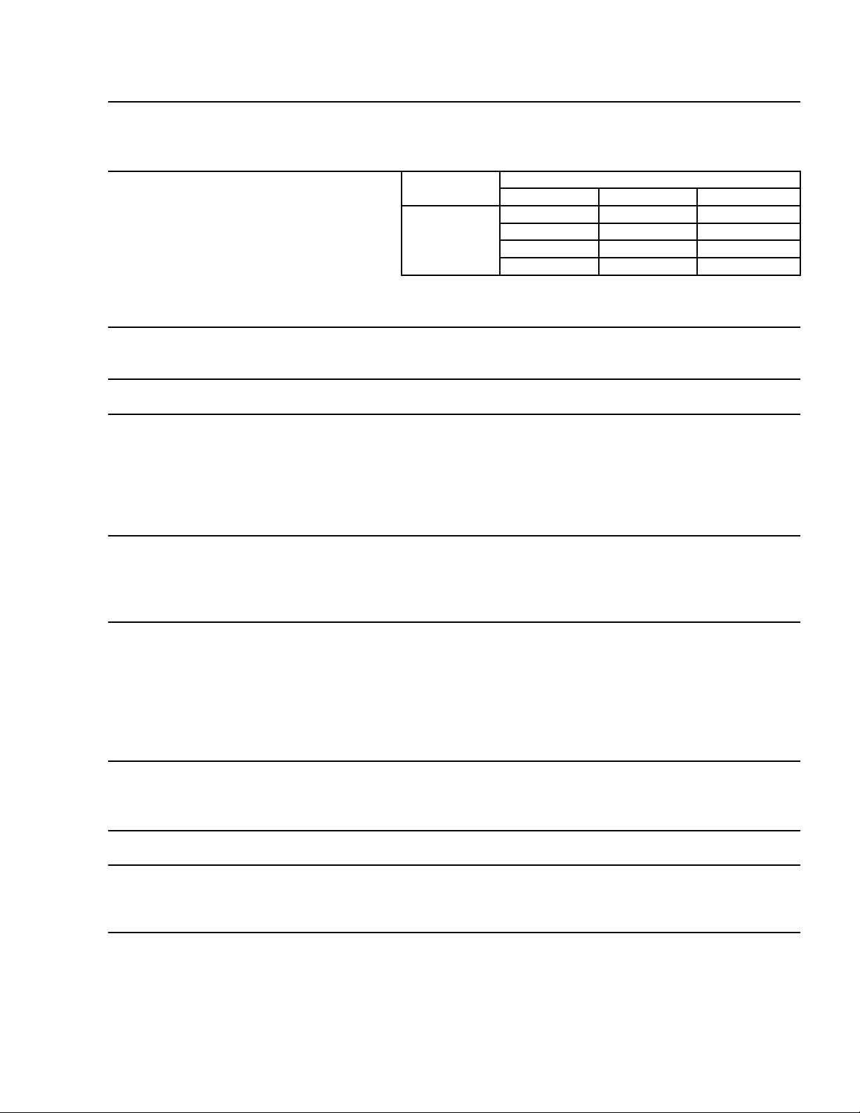
3. KM-1301SWH (water-cooled)
Note: We reserve the right to make changes in specications and design without prior
notice.
AC SUPPLY VOLTAGE 208-230/60/1 (3 wire with neutral for 115V)
AMPERAGE 8.2 A ( 5 Min. Freeze AT 104°F / WT 80°F)
MINIMUM CIRCUIT AMPACITY 20 A
MAXIMUM FUSE SIZE 20 A
APPROXIMATE ICE PRODUCTION Ambient WATER TEMP. (°F)
PER 24 HR. Temp.(°F) 50 70 90
lbs./day ( kg/day ) 70 *1318 (598) 1319 (599) 1249 (567)
Reference without *marks 80 1319 (598) 1321 (599) 1211 (549)
90 1319 (599) *1323 (600) 1228 (557)
100 1281 (581) 1301 (590) 1141 (518)
SHAPE OF ICE Crescent Cube
ICE PRODUCTION PER CYCLE 31 lbs. (14.1 kg) 1440pcs.
APPROXIMATE STORAGE CAPACITY N/A
ELECTRIC & WATER CONSUMPTION 90/70°F 70/50°F
ELECTRIC W (kWH/100 lbs.) 1760(3.2) 1740(3.2)
WATER gal./24HR (gal./100 lbs.) 257(19.4) 546(41.4)
WATER COOLED CONDENSER 1561(118) 861(65)
gal./24HR (gal./100 lbs.)
CEC/CEE TIER LEVEL 3
ENERGY STAR N/A
EXTERIOR DIMENSIONS (WxDxH) 48" x 27-3/8" x 27-3/8" (1219 x 695 x 695 mm)
EXTERIOR FINISH Stainless Steel, Galvanized Steel (Rear)
WEIGHT Net 265 lbs. (120 kg), Shipping 315 lbs. (143 kg)
CONNECTIONS - ELECTRIC Permanent - Connection
- WATER SUPPLY Inlet 1/2" FPT Cond. Inlet 1/2" FPT
- DRAIN Outlet 3/4" FPT Cond. Outlet 3/8" FPT
- CONDENSATE DRAIN 3/8" OD Tube
CUBE CONTROL SYSTEM Float Switch
HARVESTING CONTROL SYSTEM Hot Gas and Water, Thermistor and Timer
ICE MAKING WATER CONTROL Timer Controlled. Overflow Pipe
COOLING WATER CONTROL Water Regulator
BIN CONTROL SYSTEM Thermostat
COMPRESSOR Hermetic, Model CS12K6E-PFV-237
CONDENSER Water-cooled, Tube in tube type
EVAPORATOR Vertical type, Stainless Steel and Copper
REFRIGERANT CONTROL Thermostatic Expansion Valve
REFRIGERANT CHARGE R404A, 2 lb. 8.2 oz. (1140g)
DESIGN PRESSURE High 427PSIG, Low 230PSIG
P.C. BOARD CIRCUIT PROTECTION High Voltage Cut-out ( Internal )
COMPRESSOR PROTECTION Auto-reset Overload Protector ( Internal )
REFRIGERANT CIRCUIT PROTECTION Auto-reset High Pressure Control Switch
LOW WATER PROTECTION Float Switch
ACCESSORIES -SUPPLIED N/A
-REQUIRED Ice Storage Bin
OPERATING CONDITIONS VOLTAGE RANGE 187 - 253 V
AMBIENT TEMP. 45 -100° F
WATER SUPPLY TEMP. 45 - 90° F
WATER SUPPLY PRESSURE 10 - 113 PSIG
10
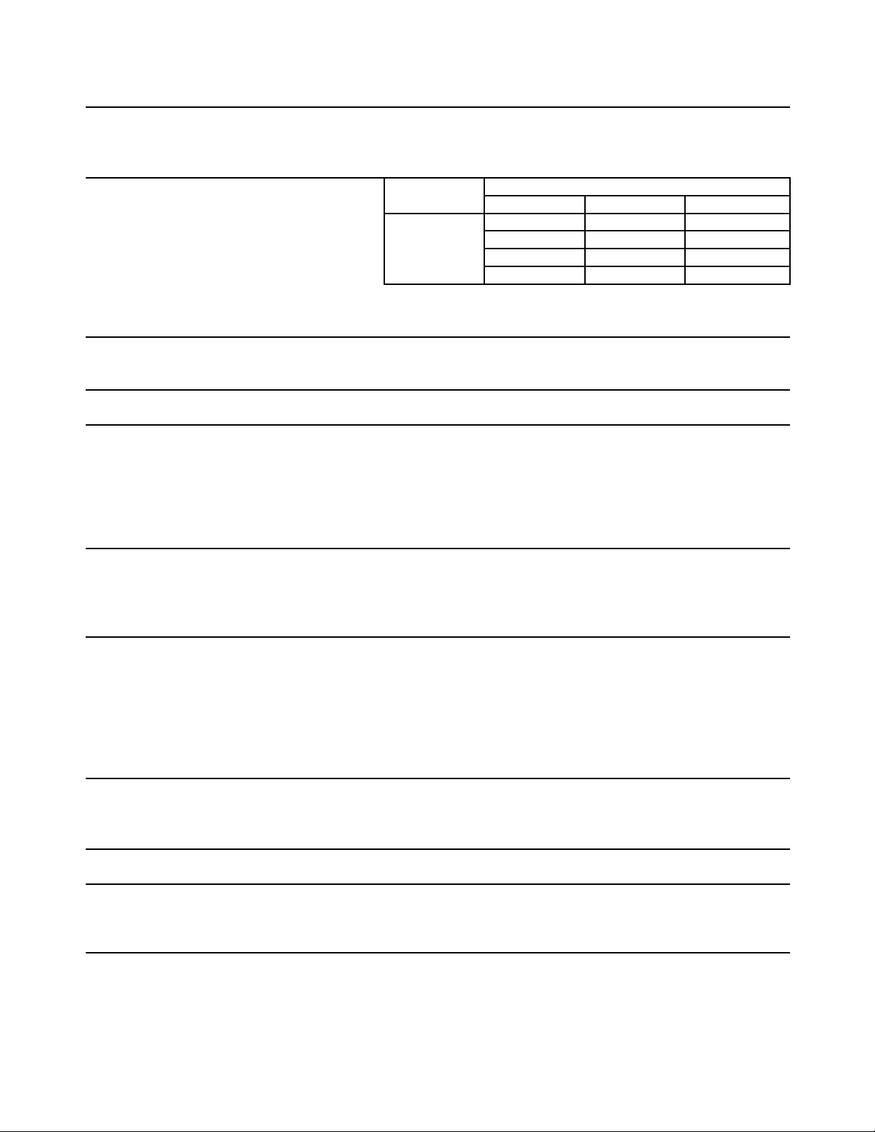
4. KM-1301SWH3 (water-cooled)
Note: We reserve the right to make changes in specications and design without prior
notice.
AC SUPPLY VOLTAGE 208-230/60/3
AMPERAGE 6.1 A ( 5 Min. Freeze AT 104°F / WT 80°F)
MINIMUM CIRCUIT AMPACITY 20 A
MAXIMUM FUSE SIZE 20 A
APPROXIMATE ICE PRODUCTION Ambient WATER TEMP. (°F)
PER 24 HR. Temp.(°F) 50 70 90
lbs./day ( kg/day ) 70 *1333 (605) 1323 (600) 1246 (565)
Reference without *marks 80 1326 (601) 1311 (594) 1198 (544)
90 1323 (600) *1300 (590) 1201 (545)
100 1286 (584) 1277 (579) 1110 (503)
SHAPE OF ICE Crescent Cube
ICE PRODUCTION PER CYCLE 32.2 lbs. (14.6 kg) 1440pcs.
APPROXIMATE STORAGE CAPACITY N/A
ELECTRIC & WATER CONSUMPTION 90/70°F 70/50°F
ELECTRIC W (kWH/100 lbs.) 1840(3.4) 1770(3.2)
WATER gal./24HR (gal./100 lbs.) 248(19.1) 557(41.8)
WATER COOLED CONDENSER 1547(119) 857(64)
gal./24HR (gal./100 lbs.)
CEC/CEE TIER LEVEL 3
ENERGY STAR N/A
EXTERIOR DIMENSIONS (WxDxH) 48" x 27-3/8" x 27-3/8" (1219 x 695 x 695 mm)
EXTERIOR FINISH Stainless Steel, Galvanized Steel (Rear)
WEIGHT Net 265 lbs. (120 kg), Shipping 315 lbs. (143 kg)
CONNECTIONS - ELECTRIC Permanent - Connection
- WATER SUPPLY Inlet 1/2" FPT Cond. Inlet 1/2" FPT
- DRAIN Outlet 3/4" FPT Cond. Outlet 3/8" FPT
- CONDENSATE DRAIN 3/8" OD Tube
CUBE CONTROL SYSTEM Float Switch
HARVESTING CONTROL SYSTEM Hot Gas and Water, Thermistor and Timer
ICE MAKING WATER CONTROL Timer Controlled. Overflow Pipe
COOLING WATER CONTROL Water Regulator
BIN CONTROL SYSTEM Thermostat
COMPRESSOR Hermetic, Model CS12K6E-TF5-237
CONDENSER Water-cooled, Tube in tube type
EVAPORATOR Vertical type, Stainless Steel and Copper
REFRIGERANT CONTROL Thermostatic Expansion Valve
REFRIGERANT CHARGE R404A, 2 lb. 8.2 oz. (1140g)
DESIGN PRESSURE High 427PSIG, Low 230PSIG
P.C. BOARD CIRCUIT PROTECTION High Voltage Cut-out ( Internal )
COMPRESSOR PROTECTION Auto-reset Overload Protector ( Internal )
REFRIGERANT CIRCUIT PROTECTION Auto-reset High Pressure Control Switch
LOW WATER PROTECTION Float Switch
ACCESSORIES -SUPPLIED N/A
-REQUIRED Ice Storage Bin
OPERATING CONDITIONS VOLTAGE RANGE 187 - 253 V
AMBIENT TEMP. 45 -100° F
WATER SUPPLY TEMP. 45 - 90° F
WATER SUPPLY PRESSURE 10 - 113 PSIG
11
5. KM-1301SRH (remote air-cooled)
Note: We reserve the right to make changes in specications and design without prior
notice.
AC SUPPLY VOLTAGE 208-230/60/1 (3 wire with neutral for 115V)
AMPERAGE 13.5A ( 5 Min. Freeze AT 104°F / WT 80°F)
MINIMUM CIRCUIT AMPACITY 20 A
MAXIMUM FUSE SIZE 20 A
APPROXIMATE ICE PRODUCTION Ambient WATER TEMP. (°F)
PER 24 HR. Temp.(°F) 50 70 90
lbs./day ( kg/day ) 70 *1353 (614) 1315 (596) 1219 (553)
Reference without *marks 80 1324 (600) 1264 (573) 1144 (519)
90 1315 (596) *1222 (554) 1110 (504)
100 1281 (581) 1196 (542) 1008 (457)
SHAPE OF ICE Crescent Cube
ICE PRODUCTION PER CYCLE 31.1 lbs. (14.1 kg) 1440pcs.
APPROXIMATE STORAGE CAPACITY N/A
ELECTRIC & WATER CONSUMPTION 90/70°F 70/50°F
ELECTRIC W (kWH/100 lbs.) 2090(4.1) 2010(3.6)
WATER gal./24HR (gal./100 lbs.) 203(16.6) 479(35.4)
CEC/CEE TIER LEVEL 3
ENERGY STAR YES
EXTERIOR DIMENSIONS (WxDxH) 48" x 27-3/8" x 27-3/8" (1219 x 695 x 695 mm)
EXTERIOR FINISH Stainless Steel, Galvanized Steel (Rear)
WEIGHT Net 255 lbs. (116 kg), Shipping 315 lbs. (143 kg)
CONNECTIONS - ELECTRIC Permanent - Connection
- WATER SUPPLY Inlet 1/2" FPT
- DRAIN Outlet 3/4" FPT
- CONDENSATE DRAIN 3/8" OD Tube
CUBE CONTROL SYSTEM Float Switch
HARVESTING CONTROL SYSTEM Hot Gas and Water, Thermistor and Timer
ICE MAKING WATER CONTROL Timer Controlled. Overflow Pipe
COOLING WATER CONTROL N/A
BIN CONTROL SYSTEM Thermostat
COMPRESSOR Hermetic, Model CS12K6E-PFV-279
CONDENSER Air-Cooled Remote, Condenser Unit URC-14F
EVAPORATOR Vertical type, Stainless Steel and Copper
REFRIGERANT CONTROL Thermostatic Expansion Valve
Condensing Pressure Regulator on URC-14F
REFRIGERANT CHARGE R404A, 10 lbs. 5.8 oz. (4700g)
(Icemaker 5 lbs. 15.2 oz. Cond. Unit 4 lbs. 6.5 oz.)
DESIGN PRESSURE High 467PSIG, Low 230PSIG
P.C. BOARD CIRCUIT PROTECTION High Voltage Cut-out ( Internal )
COMPRESSOR PROTECTION Auto-reset Overload Protector ( Internal )
REFRIGERANT CIRCUIT PROTECTION Auto-reset High Pressure Control Switch
LOW WATER PROTECTION Float Switch
ACCESSORIES -SUPPLIED N/A
-REQUIRED Ice Storage Bin, Remote Condenser Unit
OPERATING CONDITIONS VOLTAGE RANGE 187 - 253 V
AMBIENT TEMP. 45 -100° F
WATER SUPPLY TEMP. 45 - 90° F
WATER SUPPLY PRESSURE 10 - 113 PSIG
1
6. KM-1301SRH3 (remote air-cooled)
Note: We reserve the right to make changes in specications and design without prior
notice.
AC SUPPLY VOLTAGE 208-230/60/3
AMPERAGE 10.7A ( 5 Min. Freeze AT 104°F / WT 80°F)
MINIMUM CIRCUIT AMPACITY 20 A
MAXIMUM FUSE SIZE 20 A
APPROXIMATE ICE PRODUCTION Ambient WATER TEMP. (°F)
PER 24 HR. Temp.(°F) 50 70 90
lbs./day ( kg/day ) 70 *1339 (607) 1297 (589) 1203 (546)
Reference without *marks 80 1307 (593) 1243 (564) 1127 (511)
90 1297 (589) *1197 (543) 1088 (494)
100 1266 (574) 1171 (531) 988 (448)
SHAPE OF ICE Crescent Cube
ICE PRODUCTION PER CYCLE 30.7 lbs. (13.9 kg) 1440pcs.
APPROXIMATE STORAGE CAPACITY N/A
ELECTRIC & WATER CONSUMPTION 90/70°F 70/50°F
ELECTRIC W (kWH/100 lbs.) 2140(4.3) 2090(3.8)
WATER gal./24HR (gal./100 lbs.) 192(16.0) 463(34.6)
CEC/CEE TIER LEVEL 3
ENERGY STAR YES
EXTERIOR DIMENSIONS (WxDxH) 48" x 27-3/8" x 27-3/8" (1219 x 695 x 695 mm)
EXTERIOR FINISH Stainless Steel, Galvanized Steel (Rear)
WEIGHT Net 255 lbs. (116 kg), Shipping 315 lbs. (143 kg)
CONNECTIONS - ELECTRIC Permanent - Connection
- WATER SUPPLY Inlet 1/2" FPT
- DRAIN Outlet 3/4" FPT
- CONDENSATE DRAIN 3/8" OD Tube
CUBE CONTROL SYSTEM Float Switch
HARVESTING CONTROL SYSTEM Hot Gas and Water, Thermistor and Timer
ICE MAKING WATER CONTROL Timer Controlled. Overflow Pipe
COOLING WATER CONTROL N/A
BIN CONTROL SYSTEM Thermostat
COMPRESSOR Hermetic, Model CS12K6E-TF5-279
CONDENSER Air-Cooled Remote, Condenser Unit URC-14F
EVAPORATOR Vertical type, Stainless Steel and Copper
REFRIGERANT CONTROL Thermostatic Expansion Valve
Condensing Pressure Regulator on URC-14F
REFRIGERANT CHARGE R404A, 10 lbs. 5.8 oz. (4700g)
(Icemaker 5 lbs. 15.2 oz. Cond. Unit 4 lbs. 6.5 oz.)
DESIGN PRESSURE High 467PSIG, Low 230PSIG
P.C. BOARD CIRCUIT PROTECTION High Voltage Cut-out ( Internal )
COMPRESSOR PROTECTION Auto-reset Overload Protector ( Internal )
REFRIGERANT CIRCUIT PROTECTION Auto-reset High Pressure Control Switch
LOW WATER PROTECTION Float Switch
ACCESSORIES -SUPPLIED N/A
-REQUIRED Ice Storage Bin, Remote Condenser Unit
OPERATING CONDITIONS VOLTAGE RANGE 187 - 253 V
AMBIENT TEMP. 45 -100° F
WATER SUPPLY TEMP. 45 - 90° F
WATER SUPPLY PRESSURE 10 - 113 PSIG
13
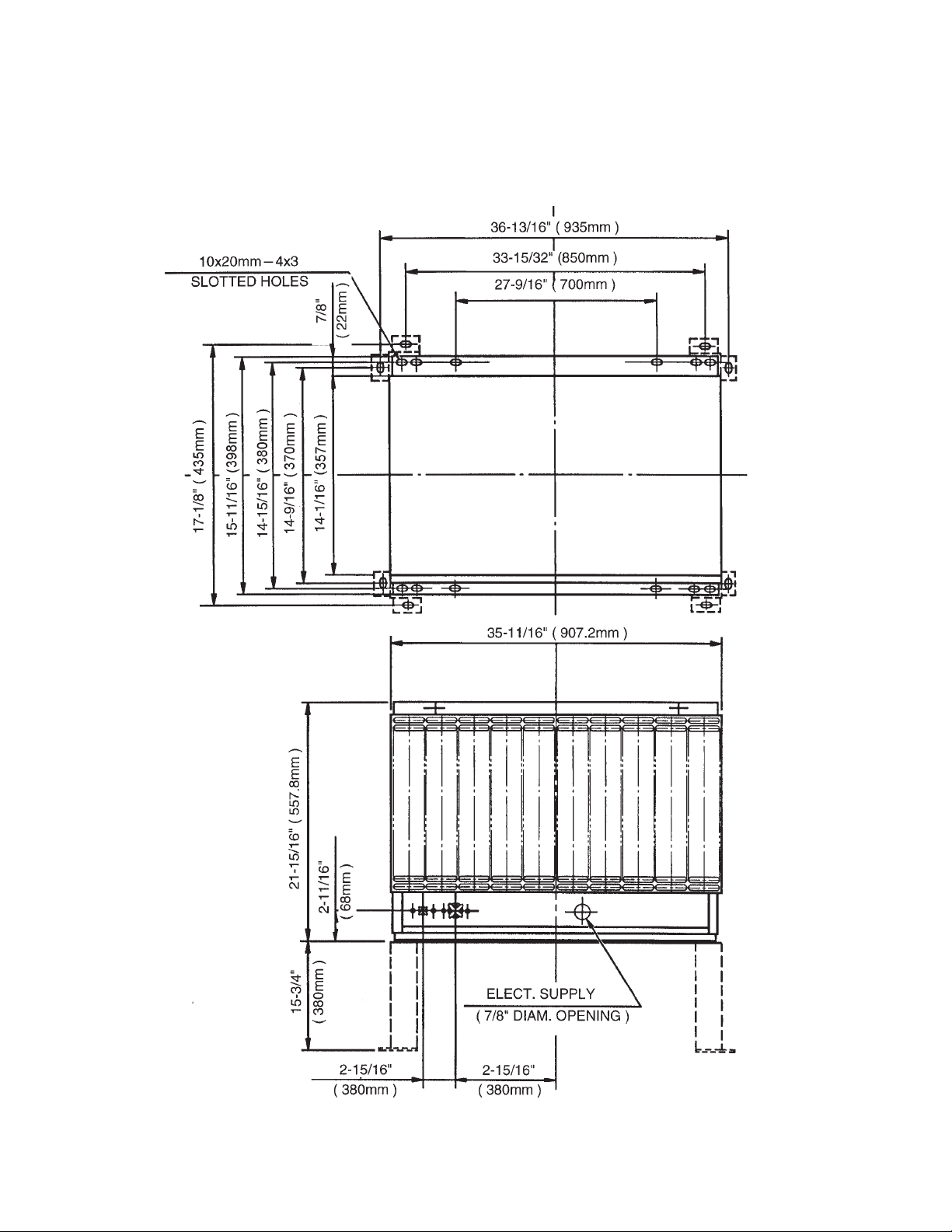
B. Condenser Unit
1. URC-14F
Unit: inches (mm)
14
SPECIFICATIONS
MODEL: URC-14F
AC SUPPLY VOLTAGE 115/60/1 (Connection to Icemaker)
FAN MOTOR 115 V Total 2.6FLA 130W
EXTERIOR DIMENSIONS (WxDxH) 35-11/16" x 15-11/16" x 21-15/16" (907.2 x 398 x 557.8 mm)
DIMENSIONS INCLUDING LEGS (WxDxH) 37-13/16" x 18-1/8" x 36-15/16" (960 x 460 x 937.8 mm)
EXTERIOR FINISH Galvanized Steel
WEIGHT Net 80 lbs. ( 36 kg ) Shipping 87 lbs. ( 39 kg )
CONNECTIONS - ELECTRIC Permanent - Connection
- REFRIGERANT Discharge Line 1-1/16"-12 UNF Fitting (#10 AEROQUIP)
Liquid Line 5/8"-18 UNF Fitting (#6 AEROQUIP)
CONDENSER Air-cooled, Fin and tube type
FAN MOTOR PROTECTION Thermal Protection
REFRIGERANT CONTROL Condensing Pressure Regulator
REFRIGERANT CHARGE R-404A 4 lb. 7 oz. (2000g)
DESIGN PRESSURE High 467 PSIG
OPERATING CONDITIONS VOLTAGE RANGE 104 ~ 127 V
AMBIENT TEMP. -20 ~ 122 °F
ACCESSORIES -SUPPLIED Leg 2 pcs
Hex. Head Bolt w/Washer 8 x 16 8 pcs
Hex. Nut 8 8 pcs
15
II. General Information
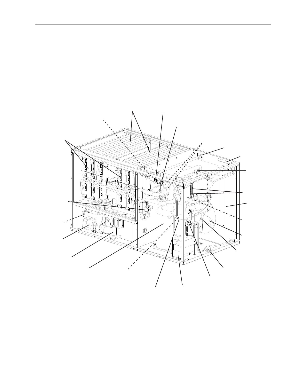
A. Construction
1. KM-1301SAH, KM-1301SAH3 (air-cooled)
Evaporator Assembly
Spray Tubes
Inlet Water Valve
Water Supply Inlet
Hot Gas Valve
Junction Box
Air-Cooled
Condenser
Check Valves
Control Box
Drier
Transformer Box
(KM-1301SAH3)
Control Switch
Bin Control Thermostat
Compressor
Cleaning Valve
Float Switch
Water Pump
Check Valve
(water)
Expansion Valves
Liquid Line Valve
Fan Motor
Fan Blade
Low-Side Service Valve
High-Side Service Valve

16
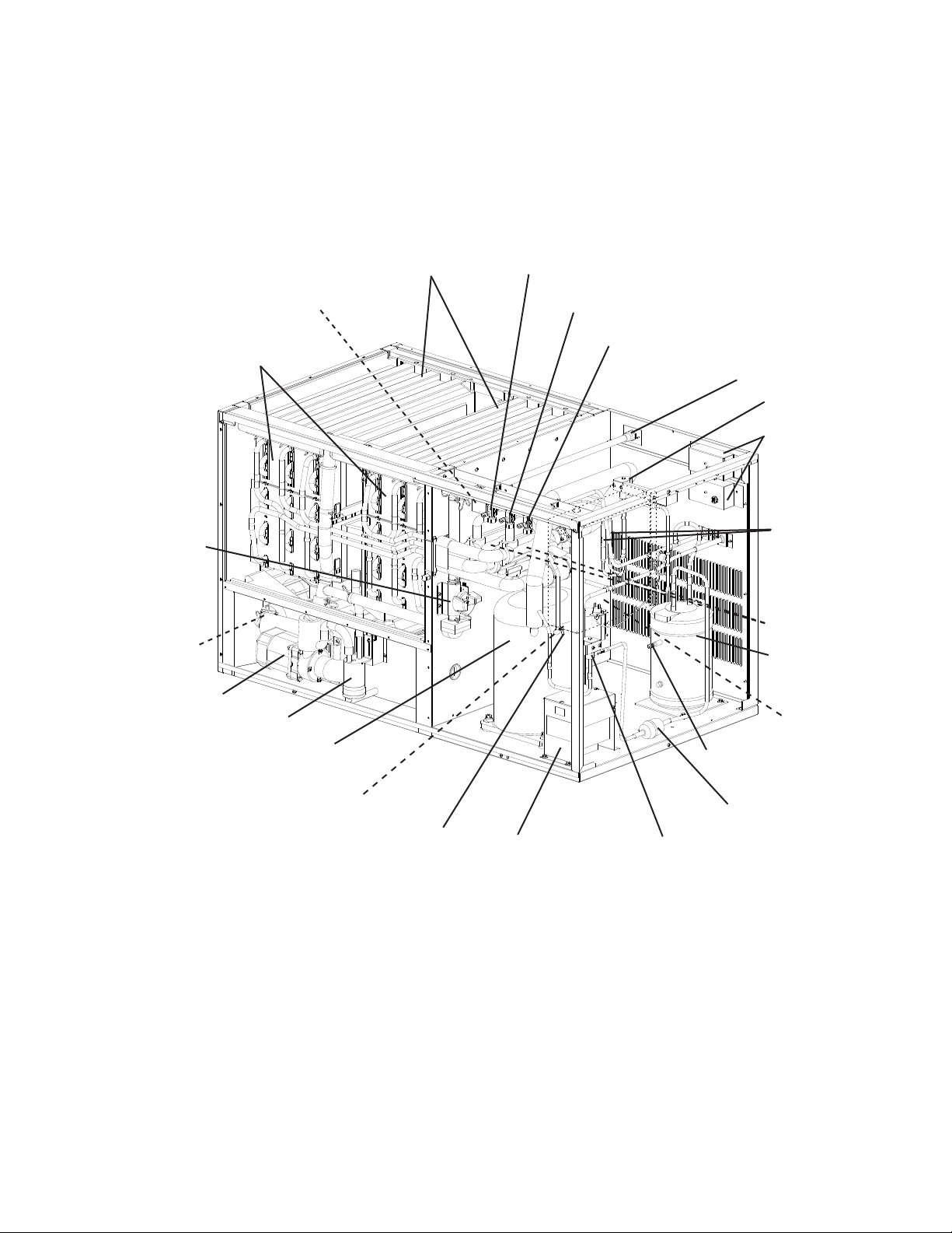
2. KM-1301SWH, KM-1301SWH3 (water-cooled)
Evaporator Assembly
Spray Tubes
Inlet Water Valve
Water Supply Inlet
Hot Gas Valve
Junction Box
Water Regulating
Valve
Check Valves
Control Box
Liquid Line Valve
Drier
Transformer Box
(KM-1301SWH3)
Control Switch
Bin Control Thermostat
Compressor
Cleaning Valve
Float Switch
Water Pump
Check Valve
(water)
Expansion Valves
Water-Cooled
Condenser
Low-Side Service Valve
High-Side Service Valve
17
3. KM-1301SRH, KM-1301SRH3 (remote air-cooled)
Evaporator Assembly
Spray Tubes
Inlet Water Valve
Water Supply Inlet
Hot Gas Valve
Junction Boxes
Receiver Tank
Check Valves
Control Box
Liquid Line Valve
Drier
Transformer Box
(KM-1301SRH3)
Control Switch
Bin Control Thermostat
Compressor
Cleaning Valve
Float Switch
Water Pump
Check Valve
(water)
Expansion Valves
Low-Side Service Valve
High-Side Service Valve
High-Side Liquid Service Valve
Access Valve

18
B. Sequence of Operation
IMPORTANT
This unit utilizes a thermostatic bin control. For operation, the K4 jumper
(4A4883G01) must be in place on the control board RED K4 connector.
1. Sequence Cycles and Shutdown
The steps in the sequence are as outlined below. When power is supplied, CB red
"POWER OK" LED and green "BC CLOSED" LED come on. The green "BC CLOSED"
LED is on continuously when the K4 jumper is in place. If CB yellow "BC OPEN" LED is
on, check that CB has the K4 jumper in place on CB RED K4 connector. This unit will not
operate unless the K4 jumper is in place. There is a 5-second delay before startup. Note
that the order of the component LEDs from the outer edge of CB is 1, 4, 3, .
a) 1-Minute Fill Cycle
LED 4 is on. WV and X relay (auxiliary code T-0 and U-0), X11 relay (auxiliary code
U-1 and later) energize and the 1-minute ll cycle begins. After 1 minute, CB checks for
a closed F/S. If F/S is closed, the harvest cycle begins. If not, WV remains energized
through additional 1-minute ll cycles until water lls the tank and closes F/S. This
serves as a low water safety to protect PM.
b) Initial Harvest Cycle
LEDs 1, 4, and are on. WV and X relay (auxiliary code T-0, U-0), X11 relay (auxiliary
code U-1 and later) remain energized, HGV, X1 relay (auxiliary code T-0, U-0),
X10 relay (auxiliary code U-1 and later), Comp, and FMR energize. CB monitors the
warming of the evaporator via the thermistor located on the suction line. When the
thermistor reaches 48°F (9°C), CB reads a 3.9 kΩ signal from the thermistor and turns
harvest termination over to the harvest timer (S4 dip switch 1 & ). The harvest timer
has settings of 60, 90, 10, and 180 seconds. For details, see "II.C.3.b) Harvest Timer
(S4 dip switch 1 & )." WV is energized during harvest for a maximum of 6 minutes or
the length of harvest minus 0 or 50 seconds (harvest pump timer (S4 dip switch 7)),
whichever is shorter. CAUTION! Do not adjust S4 dip switch 7 out of the factory
default position on this model. Adjustment outside of the factory default position
may result in damage to the icemaker. For details, see "II.C.3.e) Harvest Pump Timer
(S4 dip switch 7)." LED 4 goes off when WV and X relay (auxiliary code T-0, U-0),
X11 relay (auxiliary code U-1 and later) de-energize. LED 3 comes on and PM energizes
and runs for the last 0 or 50 seconds of harvest depending on S4 dip switch 7 setting.
This circulates water over the evaporator for the last 0 or 50 seconds of harvest. PM
is energized through the #5 pin (DBu wire) on the CB K1 ten-pin connector and the
X1 relay (auxiliary code T-0, U-0), X10 relay (auxiliary code U-1 and later). When the
harvest timer expires, the harvest cycle is complete. CB checks the position of F/S and
proceeds to the freeze cycle if it is closed or calls for a 1-minute ll cycle if it is open. The
minimum total time allowed by CB for a complete harvest cycle is minutes.
c) Freeze Cycle
LED 1 is on. Comp and FMR remain energized, PM energizes or remains energized
depending on harvest pump timer (S4 dip switch 7) setting. FM and LLV energize.
HGV and X1 relay (auxiliary code T-0, U-0), X10 relay (auxiliary code U-1 and later)
19
de-energize. For the rst 5 minutes, CB will not accept a signal from F/S. This minimum
5-minute freeze time is short cycle protection for Comp. At the end of 5 minutes, F/S
assumes control. As ice builds on the evaporator, the water level in the tank lowers. The
freeze cycle continues until F/S opens and terminates the cycle. There is a 15 second
delay before CB acknowledges an open F/S.
d) Pump-Out Cycle
LEDs 1, 3, and are on. LED 4 is on when S4 dip switch 3 & 4 are set to 3 off and 4 on.
CAUTION! Do not adjust S4 dip switch 3 & 4 to 3 off and 4 on. Adjustment to this
position on this model prevents the unit from operating correctly and may cause
damage. For details, see "II.C.3.c) Pump-Out Timer (S4 dip switch 3 & 4)." Comp and
FMR remain energized, HGV energizes, WV energizes if S4 dip switch 3 off and 4 on.
LLV and FM de-energize. PM stops for seconds then reverses, taking water from the
bottom of the tank and forcing pressure against the check valve seat allowing water to
go through the check valve and down the drain. At the same time, water ows through
the small tube to power ush F/S. When the pump-out timer expires, the pump-out is
complete.
The rst pump-out occurs after the 11th freeze cycle, then every 10th cycle thereafter.
The pump-out frequency control is factory set, and generally no adjustment is required.
However, where water quality is bad and the icemaker needs a pump-out more often, the
pump-out frequency can be adjusted. The pump-out frequency control (S4 dip switch 5 &
6) can be set to have a pump-out occur every cycle, or every , 5, or 10 cycles. Timing of
the rst pump-out is dependent on S4 dip switch 5 & 6 settings. See the table below. For
details, see "II.C.3.d) Pump-Out Frequency Control (S4 dip switch 5 & 6)."
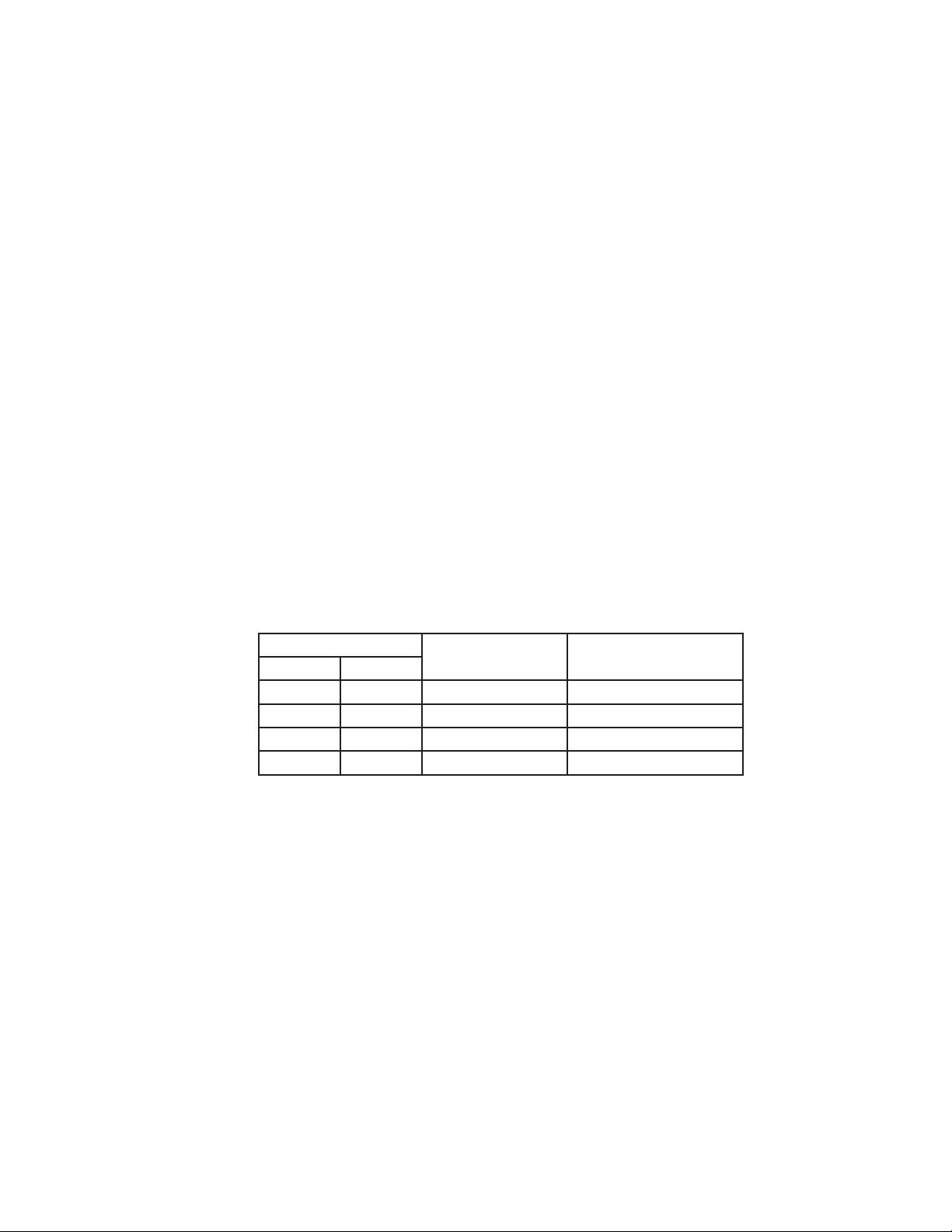
S4 Dip Switch Setting
Pump-Out
Frequency
1st Pump-Out
No. 5 No. 6
OFF OFF Every cycle After nd freeze cycle
ON OFF Every cycles After 3rd freeze cycle
OFF ON Every 5 cycles After 6th freeze cycle
ON ON Every 10 cycles After 11th freeze cycle
e) Harvest Cycle
Same as the initial harvest cycle. See "II.B.1.b) Initial Harvest Cycle."
Note: Unit continues to cycle until BC is satised or power is turned off. The unit always
restarts at the 1-minute ll cycle.
f) Shutdown
When ice contacts the thermostatic bulb (BC switch open), BC shuts down the unit within
10 seconds. The bin control is factory set, and generally no adjustment is required.
However, adjustment may be needed in some conditions, particularly at higher altitude
locations.
Legend: BC–bin control; CB–control board; Comp–compressor; FMR–fan motor-remote;
FM–fan motor; F/S–oat switch; HGV–hot gas valve; LLV–liquid line valve;
PM–pump motor; WV–inlet water valve
0
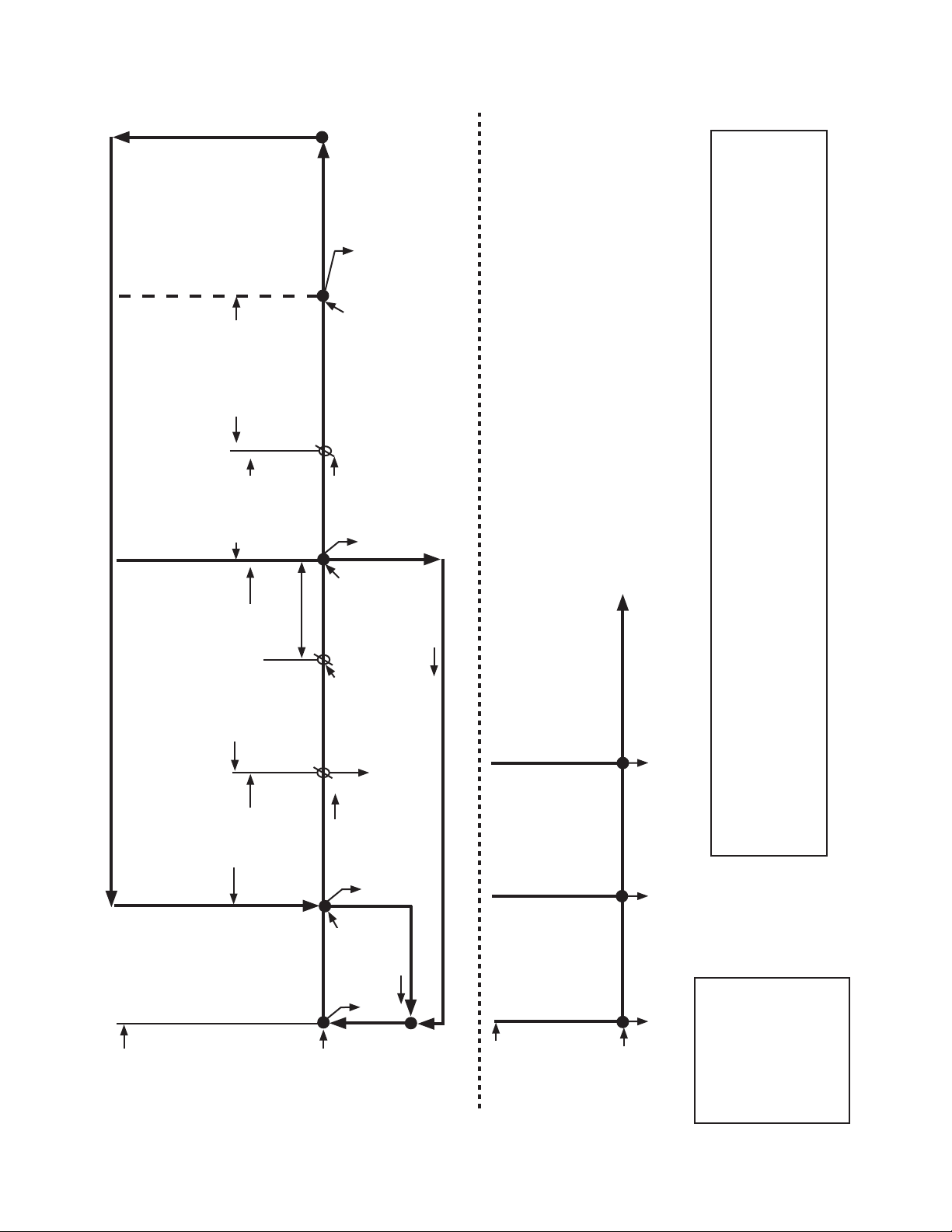
2. Sequence Flow Chart
• WV time: 6 min. or the length of harvest minus 0 or
50 sec. (S4 dip switch 7), whichever is shorter. DO
NOT ADJUST S4 dip switch 7 on this model.
• Maximum harvest time: 0 min.
F/S check
1 to 3-min. timer in control
(S4 dip switch 1 & )
Legend:
BC–bin control
Comp–compressor
FM–fan motor
FMR–fan motor-remote
F/S–oat switch
HGV–hot gas valve
LLV–liquid line valve
PM–pump motor
WV–inlet water valve
Components Energized when the Control Switch is in the "WASH" Position
The "WASH" position on the control switch is used when cleaning and sanitizing the unit. When in the "WASH" position, power is
supplied to the pump motor. With the cleaning valve closed, the cleaner and sanitizer ow over the outside of the evaporator plate
assembly. With the cleaning valve open, the cleaner and sanitizer ow over both the outside and the inside of the evaporator plate
assembly.
Note: Close the cleaning valve after cleaning and sanitizing are complete, otherwise the unit will not restart when the control
switch is placed in the "ICE" position.
"G" Control Board Sequence Flow Chart
1. 1-Minute
Fill Cycle
Cycle Steps
2. Harvest Cycle
Thermistor
in control
3. Freeze Cycle
• Minimum freeze time: 5 min.
• Maximum freeze time: freeze timer setting
(S4 dip switch 9 & 10)
F/S in control
4. Pump-Out Cycle
• Factory set for every
10th cycle (S4 dip
switch 5 & 6)
• Pump motor stops
for sec., then
reverses for 10/0
sec. (S4 dip switch
3 & 4)
WV energized
F/S open
WV continues
Comp energized
FMR energized
HGV energized
Thermistor temperature
reaches 48°F (9°C)
(3.9 kΩ or less).
Harvest timer starts.
F/S open
Comp continues
FMR continues
PM continues
FMS energized
LLV energized
HGV de-energized
F/S closed
Comp continues
FMR continues
HGV energized
PM de-energizes for sec.,
then reverses for 10/0 sec.
FM de-energized
LLV de-energized
F/S check
Initial startup
begins here
after 5-sec.
delay
If F/S is open, compressor stops and cycle returns to 1-Minute Fill Cycle
5-min. timer in
control
F/S closed
F/S open or freeze
timer expires
NOTE: Green "BC CLOSED" LED on continuously
when the K4 jumper is in place.
0 or 50 sec.
PM energized
WV de-energized
Harvest Pump
Timer
1. Bin Full
Within 10 sec.
after ice contacts
thermostatic bulb,
unit shuts down.
Shutdown
and Restart
BC Operation
Ice contacts
thermostatic bulb
2. Icemaker Off
All components
de-energized.
3. Ice Level Lowered
No ice touching
thermostatic bulb.
Icemaker starts at
"1. 1-Minute Fill Cycle."
BC closed
BC-open
All components
de-energized
To 1 above
KM-1301SAH/3, KM-1301SWH/3, and KM-1301SRH/3

1
C. Control Board
• A Hoshizaki exclusive solid-state control board is employed in KM-1301SAH/3,
KM-1301SWH/3, and KM-1301SRH/3, Stackable Crescent Cubers.
• All models are pretested and factory set.
CAUTION
1. The control board is fragile; handle very carefully.
. The control board contains integrated circuits, which are susceptible to
failure due to static discharge. It is especially important to touch the metal
part of the unit before handling or replacing the control board.
3. Do not touch the electronic devices on the control board or the back of the
control board.
4. Do not change wiring and connections. Do not misconnect K3, K4, and K5,
because the same connector is used for the thermistor, K4 jumper, and oat
switch. The control board RED K4 connector must have the K4 jumper in
place for proper operation.
5. Always replace the whole control board assembly if it goes bad.
6. Do not short out power supply to test for voltage.
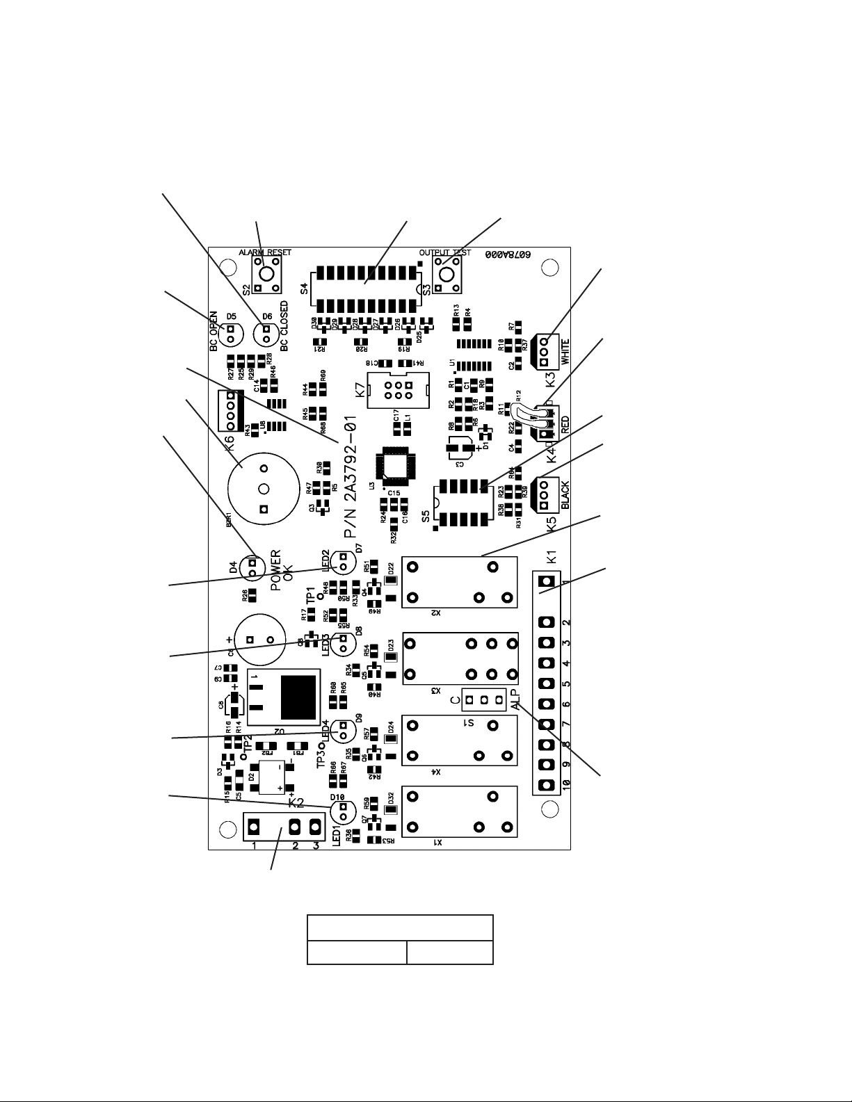
1. Control Board Layout
Control Board
Part Number A379-01
"G" Control Board
"ALARM RESET" Button
"OUTPUT TEST" Button
(used to test relays on control board)
WHITE K3 Connector
Harvest Control
(thermistor)
RED K4 Connector
K4 Jumper (4A4883G01
thermostatic bin control
application) or Mechanical
Bin Control
Label
(control board revision
level indicated on label
on side of relay)
BLACK K5 Connector
Float Switch
Part Number
K1 Ten-Pin Connector
Pins #1 through #10
#1, 9 Magnetic Contactor
# Hot Gas Valve (HGV)
#3 Liquid Line Valve (LLV),
Fan Motor (FM)
#4 Pump Motor (icemaking)
#5 Pump Motor (pump-out,
harvest (if applicable))
#6 Inlet Water Valve (WV)
#7, 10 Component Power
Supply
#8 Open
Switch for "C" control board
and "ALPINE" control board
(service control board only)
Bin Control Switch
Open LED (yellow)
(mechanical bin control
application only)
S4 Dip
Switch
Bin Control Switch
Closed LED (green)
(on continuously
in thermostatic bin
control application)
Alarm Buzzer
Power LED (red)
(lights when
power is supplied to
the control board)
LED (X Relay)
Hot Gas Valve (HGV)
Fan Motor (FM)
(FM off when LED on)
LED 3 (X3 Relay)
Pump Motor (PM)
(on at pump-out,
harvest (if applicable))
LED 4 (X4 Relay)
Inlet Water Valve (WV)
LED 1 (X1 Relay)
Compressor (Comp),
Fan Motor-Remote
(FMR)
K Connector
Transformer
S5 Dip Switch
Relay LEDs (4)
(indicate which
relays are energized
as listed below)

3
2. Features
a) Maximum Water Supply Period - 6 minutes
The inlet water valve will be open during harvest for 6 minutes or the length of harvest
minus 0 or 50 seconds (harvest pump timer (S4 dip switch 7)), whichever is shorter. For
details, see "II.C.3.e) Harvest Pump Timer (S4 dip switch 7)."
b) Harvest Backup Timer and Freeze Timer
The harvest backup timer shuts down the icemaker if, for two cycles in a row, the harvest
cycle takes more than 0 minutes to complete. The control board will signal this problem
using beeps every 3 seconds.
The freeze timer shuts down the icemaker if, for two cycles in a row, the freeze cycle
takes longer than the time specied to complete. The control board will signal this
problem using 3 beeps every 3 seconds. The freeze timer is factory set using S4 dip
switch 9 & 10. For details, see "II.C.3.g) Freeze Timer (S4 dip switch 9 & 10).
The "ALARM RESET" button on the control board must be pressed with power on to
reset either of these safeties.
c) High Temperature Safety
The temperature of the suction line in the refrigeration circuit is limited by the high
temperature safety. This protects the unit from excessively high temperatures. If the
evaporator temperature reaches 17°F±7°F (53°C±4°C), the control board reads a .8 kΩ
signal from the thermistor and shuts down the icemaker.
The control board will signal this problem using 1 beep every 3 seconds. The "ALARM
RESET" button on the control board must be pressed with power on to reset the safety.
d) Low Water Safety
The control board checks the position of the oat switch at the end of the initial 1-minute
ll cycle and at the end of each harvest cycle. If the oat switch is in the up position
(electrical circuit closed), the control board changes to the next cycle. If the oat switch
is in the down position (electrical circuit open), the control board changes to additional
1-minute ll cycles until water enters the tank and closes the oat switch. When the oat
switch closes, the control board changes to the next cycle. The unit will not start without
adequate water in the tank. This serves as a low water safety to protect the water pump.
For water-cooled model, if the condenser water supply is shut off, the unit is protected by
the high-pressure switch.
e) High Voltage and Low Voltage Cut-outs
The maximum and minimum allowable supply voltages of this icemaker are limited by
the high voltage and low voltage cut-outs. If miswiring (especially on single phase 3 wire
models) causes excessive voltage (147Vac±5% or more), the high voltage cut-out shuts
down the circuit in 3 seconds and the icemaker automatically stops. The control board
will signal this problem using 7 beeps every 3 seconds.
The icemaker also automatically stops in cases of insufcient voltage (9Vac±5% or
less). The control board will signal this problem using 6 beeps every 3 seconds.
When the proper supply voltage is resumed, the icemaker automatically starts running
again.
4
f) LED Lights and Audible Alarm Safeties
At startup, a 5-second delay occurs while the control board conducts an internal timer
check. A beep occurs when the control switch is moved to the "ICE" position.
The red LED indicates proper control voltage and will remain on unless a control voltage
problem occurs. The green LEDs 1 through 4 energize and sequence from initial startup
as listed in the table below. Note that the order of the LEDs from the outer edge of the
control board is 1, 4, 3, . For details, see "II.B. Sequence of Operation."
Sequence Step LED
Energized
Components
Time LEDs are On
Min. Max. Avg.
1-Minute Fill Cycle 4 WV 1 minute
Harvest Cycle 1, 4, Comp, FMR, WV,
HGV
minutes 0 minutes 3 to 5 minutes
Harvest Pump Timer 1, 3, Comp, FMR, PM,
HGV
0 seconds 50 seconds harvest pump timer
setting
Freeze Cycle 1 Comp, FM/FMR,
PM, LLV
5 minutes freeze timer
setting
30 to 35 minutes
Pump-Out Cycle 1, 4*, 3, Comp, FMR, WV*,
PM, HGV
10 seconds 0 seconds *pump-out timer
setting
The built-in safeties shut down the unit and have alarms as listed below.
No. of Beeps
(every 3 sec.)
Type of Alarm Notes
1 High Evaporator Temp.
(temperature > 17°F)
(53°C)
Check for harvest problem (stuck HGV or relay), hot
water entering unit, stuck HM, or shorted thermistor.
Harvest Backup Timer
(harvest > 0 min. for two cycles
in a row)
Check for open thermistor, HGV not opening, TXV or
LLV leaking by, low charge, or inefcient Comp.
3 Freeze Timer
(freeze > specied setting for
two cycles in a row)
Timer is factory set using S4 dip
switch 9 & 10
Check for F/S stuck closed (up), WV leaking by, HGV
leaking by, PM not pumping, TXV not feeding properly,
LLV not opening, low charge, HM not bypassing, or
inefcient Comp.
To reset the above safeties, press the "ALARM RESET" button with the power supply on.
6 Low Voltage
(9Vac±5% or less)
Red LED will turn off if voltage protection operates.
The control voltage safeties automatically reset when
voltage is corrected.
7 High Voltage
(147Vac±5% or more)
Legend: Comp–compressor; FM–fan motor; FMR–fan motor-remote; F/S–oat switch;
HGV–hot gas valve; HM–headmaster (C.P.R.); LLV–liquid line valve; PM–pump
motor; TXV–thermostatic expansion valve; WV–inlet water valve
5
3. Controls and Adjustments
CAUTION
Dip switches are factory set. Failure to maintain factory settings may adversely
affect performance and warranty coverage. For more information, contact
Hoshizaki Technical Support at 1-800-33-1940.
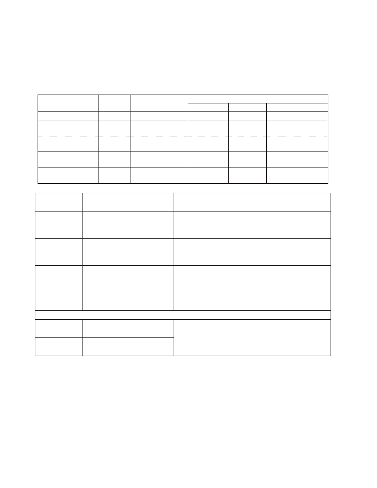
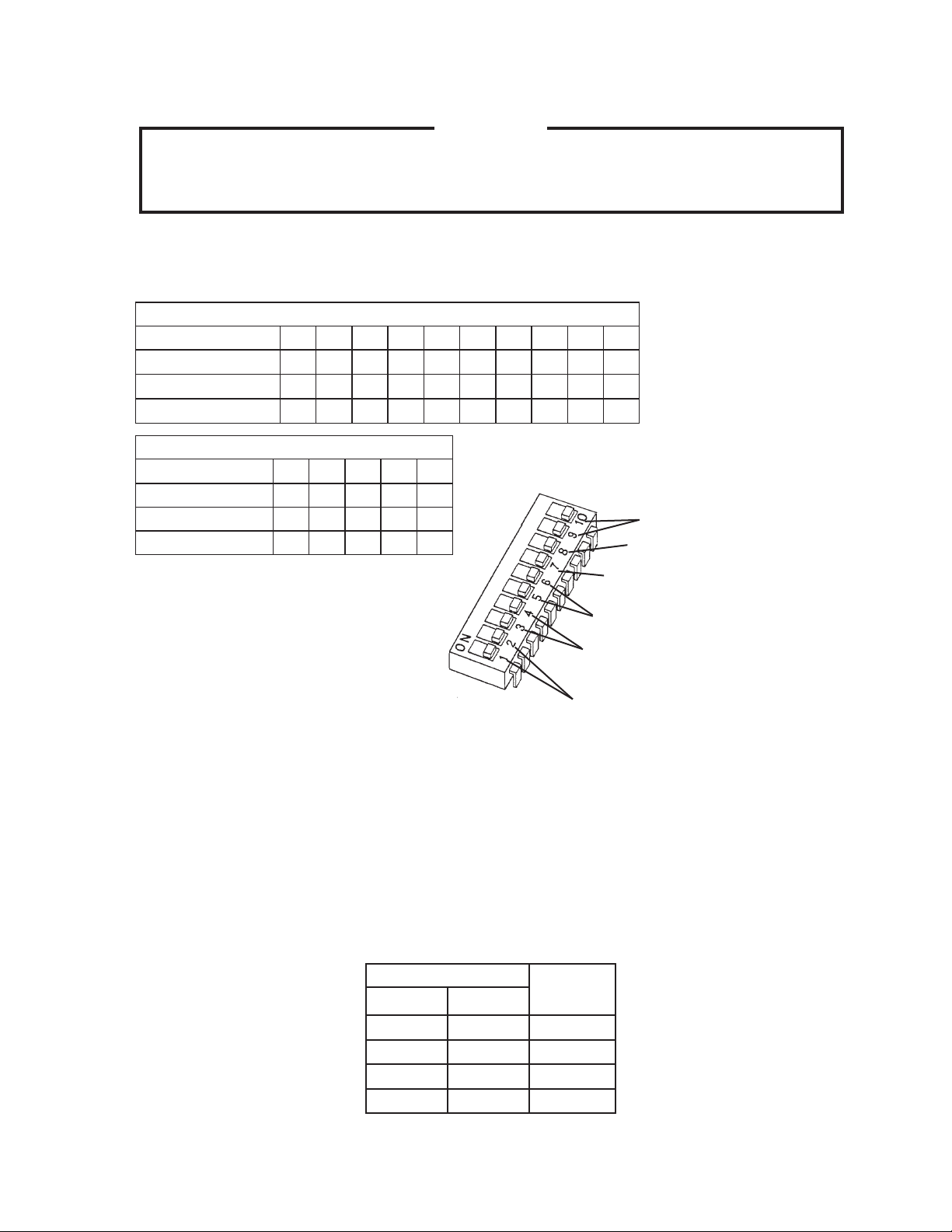
a) Default Dip Switch Settings
The dip switches are factory set to the following positions:
S4 Dip Switch
S4 Dip Switch No. 1 2 3 4 5 6 7 8 9 10
KM-1301SAH/3
OFF OFF ON ON ON ON ON OFF OFF OFF
KM-1301SWH/3
OFF OFF ON ON ON ON ON OFF OFF OFF
KM-1301SRH/3
OFF OFF ON ON ON ON ON OFF ON OFF
S5 Dip Switch (Do Not Adjust)
S5 Dip Switch No.
1 2 3 4 5
KM-1301SAH/3 OFF OFF OFF OFF OFF
KM-1301SWH/3 OFF OFF OFF OFF OFF
KM-1301SRH/3 OFF OFF OFF OFF OFF
Freeze Timer (9 & 10)
Pump-Out Frequency Control (5 & 6)
Pump-Out Timer (3 & 4)
(Do not adjust to 3 off and 4 on)
Harvest Timer (1 & )
Harvest Pump Timer (7)
(Do not adjust)
Factory Use (8)
b) Harvest Timer (S4 dip switch 1 & 2)
The harvest timer starts when the thermistor reads 48°F (9°C) at the evaporator outlet
and the control board reads the thermistor's 3.9 KΩ signal. The harvest timer is factory
set, and generally no adjustment is required. However, a setting longer than the factory
setting may be advised in cases where the ush provided at harvest needs to be
prolonged for extra cleaning. Before changing this setting, contact Hoshizaki Technical
Support at 1-800-33-1940 for recommendations. Keep in mind that setting the harvest
timer to a longer setting decreases 4-hour production.
S4 Dip Switch Setting Time
(seconds)
No. 1 No. 2
OFF OFF 60
ON OFF 90
OFF ON 10
ON ON 180
6
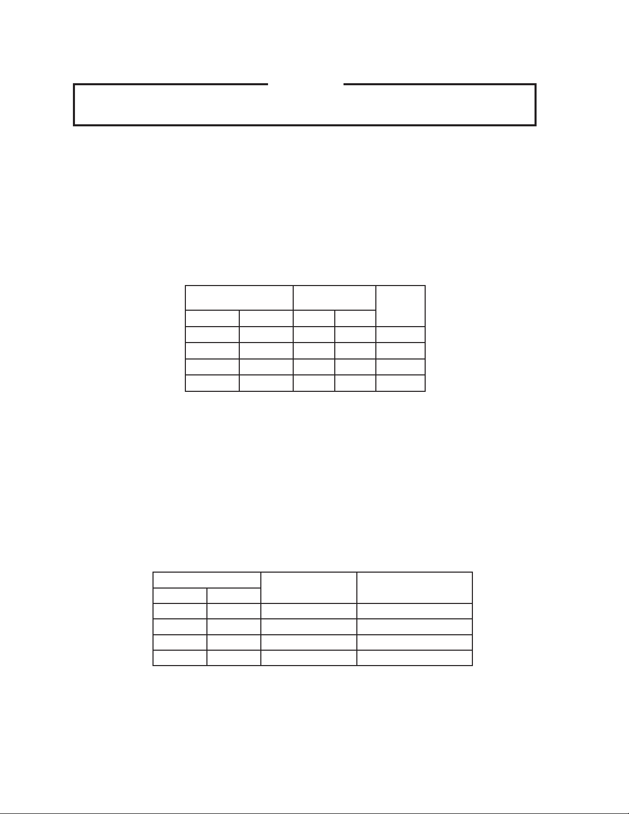
c) Pump-Out Timer (S4 dip switch 3 & 4)
CAUTION
Do not adjust S4 dip switch 3 off and S4 dip switch 4 on for this model.
Otherwise, pump motor does not rotate in the pump-out direction.
When a pump-out is called for, the pump motor stops after the preceding freeze cycle.
The pump motor restarts seconds later in the reverse direction, taking water from the
bottom of the tank and forcing pressure against the check valve seat allowing water to
go through the check valve and down the drain. At the same time, water ows through
the small tube to power ush the oat switch. The pump motor drains the water tank
for the time determined by the pump-out timer. The pump-out timer also acts in place
of the harvest timer during cycles with a pump-out. The pump-out timer is factory set,
and generally no adjustment is required. However, where water quality is bad and the
icemaker needs a longer pump-out time, the pump-out timer can be adjusted. The
pump-out timer control can be set to pump-out for 10 or 0 seconds.
S4 Dip Switch Setting Time (seconds)
Inlet
Water
Valve
No. 3 No. 4
T1
T2
OFF OFF 10 150 closed
ON OFF 10 180 closed
OFF ON 10 10 open
ON ON 0 180 closed
T1: Time to drain the water tank
T: Harvest timer at pump-out
d) Pump-Out Frequency Control (S4 dip switch 5 & 6)
The pump-out frequency control is factory set to drain the water tank every 10 cycles,
and generally no adjustment is required. However, where water quality is bad and the
icemaker needs a pump-out more often, the pump-out frequency can be adjusted. The
pump-out frequency control can be set to have a pump-out occur every cycle, or every
, 5, or 10 cycles.
Timing of the rst pump-out is dependent on S4 dip switch 5 & 6 settings. The rst
pump-out is factory set to occur after the 11th freeze cycle. See the table below.
S4 Dip Switch Setting
Pump-Out
Frequency
1st Pump-Out
No. 5 No. 6
OFF OFF Every cycle After nd freeze cycle
ON OFF Every cycles After 3rd freeze cycle
OFF ON Every 5 cycles After 6th freeze cycle
ON ON Every 10 cycles After 11th freeze cycle
Loading...